2012 MERCEDES-BENZ GLK SUV width
[x] Cancel search: widthPage 189 of 381
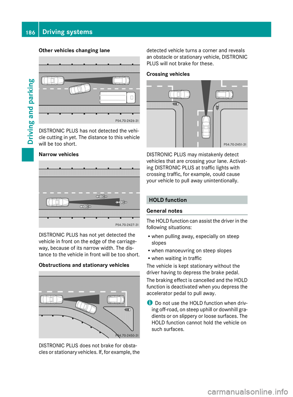
Other vehicles changing lane
DISTRONIC PLUS has not detected the vehi-
cle cutting in yet. The distance to this vehicle
will be too short.
Narrow vehicles DISTRONIC PLUS has not yet detected the
vehicle in front on the edge of the carriage-
way, because of its narrow width. The dis-
tance to the vehicle in front will be too short.
Obstructions and stationary vehicles DISTRONIC PLUS does not brake for obsta-
cles or stationary vehicles. If, for example, the detected vehicle turns a corner and reveals
an obstacle or stationary vehicle, DISTRONIC
PLUS will not brake for these.
Crossing vehicles
DISTRONIC PLUS may mistakenly detect
vehicles that are crossing your lane. Activat-
ing DISTRONIC PLUS at traffic lights with
crossing traffic, for example, could cause
your vehicle to pull away unintentionally.
HOLD function
General notes The HOLD function can assist the driver in the
following situations:
R
when pulling away, especially on steep
slopes
R when manoeuvring on steep slopes
R when waiting in traffic
The vehicle is kept stationary without the
driver having to depress the brake pedal.
The braking effect is cancelled and the HOLD
function is deactivated when you depress the
accelerator pedal to pull away.
i Do not use the HOLD function when driv-
ing off-road, on steep uphill or downhill gra-
dients or on slippery or loose surfaces. The
HOLD function cannot hold the vehicle on
such surfaces. 186
Driving systemsDriving and parking
Page 201 of 381
To deactivate:
the reversing camera is deac-
tivated if you:
R shift the transmission to position P
R drive forwards 10 m
R shift the transmission from Rto another
position (after 15 seconds)
R drive forwards at a speed of over
10 km/h
Displays in the COMAND display G
WARNING
Using the reversing camera can be dangerous
if you are colour-blind or if your ability to dis-
tinguish colours is impaired.
Only use the reversing camera if you can see
and distinguish between all the coloured
guide lines that are displayed by the reversing
camera in the COMAND display. G
WARNING
Please note that objects not at ground level
may appear to be further away than they
actually are. These include:
R the bumper of a vehicle that is parked
behind your vehicle
R a trailer drawbar
R the ball coupling of a trailer tow hitch
R the tail-end of a lorry
R slanted posts
The lines are only guides, not accurate meas-
urements of the distance to an obstacle.
Therefore, you should never pass the red line
when approaching an obstacle. You could oth-
erwise cause an accident and injure yourself
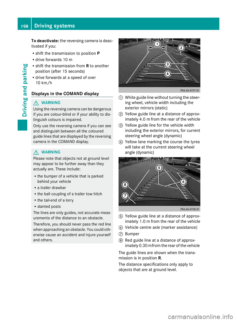
and others. :
White guide line without turning the steer-
ing wheel, vehicle width including the
exterior mirrors (static)
; Yellow guide line at a distance of approx-
imately 4.0 mfrom the rear of the vehicle
= Yellow guide line for the vehicle width
including the exterior mirrors, for current
steering wheel angle (dynamic)
? Yellow lane marking the course the tyres
will take at the current steering wheel
angle (dynamic) A
Yellow guide line at a distance of approx-
imately 1.0 m from the rear of the vehicle
B Vehicle centre axle (marker assistance)
C Bumper
D Red guide line at a distance of approx-
imately 0.30 mfrom the rear of the vehicle
The guide lines are shown when the trans-
mission is in position R.
The distance specifications only apply to
objects that are at ground level. 198
Driving systemsDriving and parking
Page 202 of 381
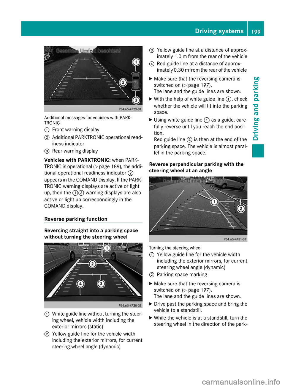
Additional messages for vehicles with PARK-
TRONIC
: Front warning display
; Additional PARKTRONIC operational read-
iness indicator
= Rear warning display
Vehicles with PARKTRONIC: when PARK-
TRONIC is operational (Y page 189), the addi-
tional operational readiness indicator ;
appears in the COMAND Display. If the PARK-
TRONIC warning displays are active or light
up, then the :=warning displays are also
active or light up correspondingly in the
COMAND display.
Reverse parking function Reversing straight into a parking space
without turning the steering wheel :
White guide line without turning the steer-
ing wheel, vehicle width including the
exterior mirrors (static)
; Yellow guide line for the vehicle width
including the exterior mirrors, for current
steering wheel angle (dynamic) =
Yellow guide line at a distance of approx-
imately 1.0 m from the rear of the vehicle
? Red guide line at a distance of approx-
imately 0.30 mfrom the rear of the vehicle
X Make sure that the reversing camera is
switched on (Y page 197).
The lane and the guide lines are shown.
X With the help of white guide line :, check
whether the vehicle will fit into the parking
space.
X Using white guide line :as a guide, care-
fully reverse until you reach the end posi-
tion.
Red guide line ?is then at the end of the
parking space. The vehicle is almost paral-
lel in the parking space.
Reverse perpendicular parking with the
steering wheel at an angle Turning the steering wheel
:
Yellow guide line for the vehicle width
including the exterior mirrors, for current
steering wheel angle (dynamic)
; Parking space marking
X Make sure that the reversing camera is
switched on (Y page 197).
The lane and the guide lines are shown.
X Drive past the parking space and bring the
vehicle to a standstill.
X While the vehicle is at a standstill, turn the
steering wheel in the direction of the park- Driving systems
199Driving and parking Z
Page 203 of 381
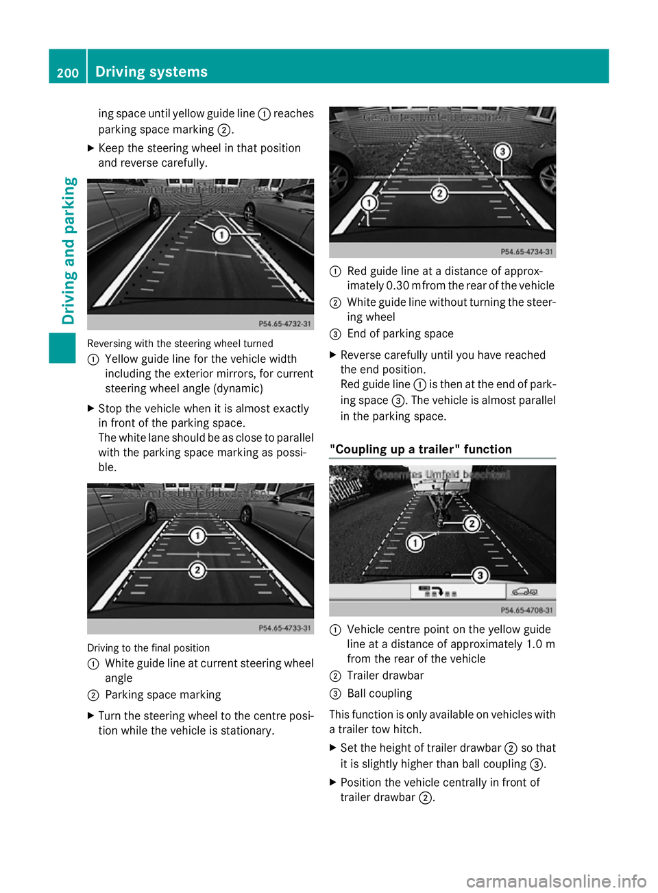
ing space until yellow guide line
:reaches
parking space marking ;.
X Keep the steering wheel in that position
and reverse carefully. Reversing with the steering wheel turned
:
Yellow guide line for the vehicle width
including the exterior mirrors, for current
steering wheel angle (dynamic)
X Stop the vehicle when it is almost exactly
in front of the parking space.
The white lane should be as close to parallel
with the parking space marking as possi-
ble. Driving to the final position
:
White guide line at current steering wheel
angle
; Parking space marking
X Turn the steering wheel to the centre posi-
tion while the vehicle is stationary. :
Red guide line at a distance of approx-
imately 0.30 mfrom the rear of the vehicle
; White guide line without turning the steer-
ing wheel
= End of parking space
X Reverse carefully until you have reached
the end position.
Red guide line :is then at the end of park-
ing space =. The vehicle is almost parallel
in the parking space.
"Coupling up a trailer" function :
Vehicle centre point on the yellow guide
line at a distance of approximately 1.0 m
from the rear of the vehicle
; Trailer drawbar
= Ball coupling
This function is only available on vehicles with
a trailer tow hitch.
X Set the height of trailer drawbar ;so that
it is slightly higher than ball coupling =.
X Position the vehicle centrally in front of
trailer drawbar ;.200
Driving systemsDriving and parking
Page 207 of 381
vehicles, such as motorcycles or bicycles, or
only detect them too late.
Monitoring may be affected by dirty sensors,
strong spray or poor visibility caused by snow,
rain or mist, for example. In this case, vehicles
are detected late or not at all.
Always pay attention to traffic conditions and
your surroundings. Otherwise, you may fail to
recognise dangers in time, cause an accident
and injure yourself and others.
For Blind Spot Assist to assist you when driv-
ing, the radar sensor system must be activa-
ted (Y page 242) and operational.
The radar sensor system is switched off auto-
matically in the vicinity of radio telescope
facilities (Y page 375).
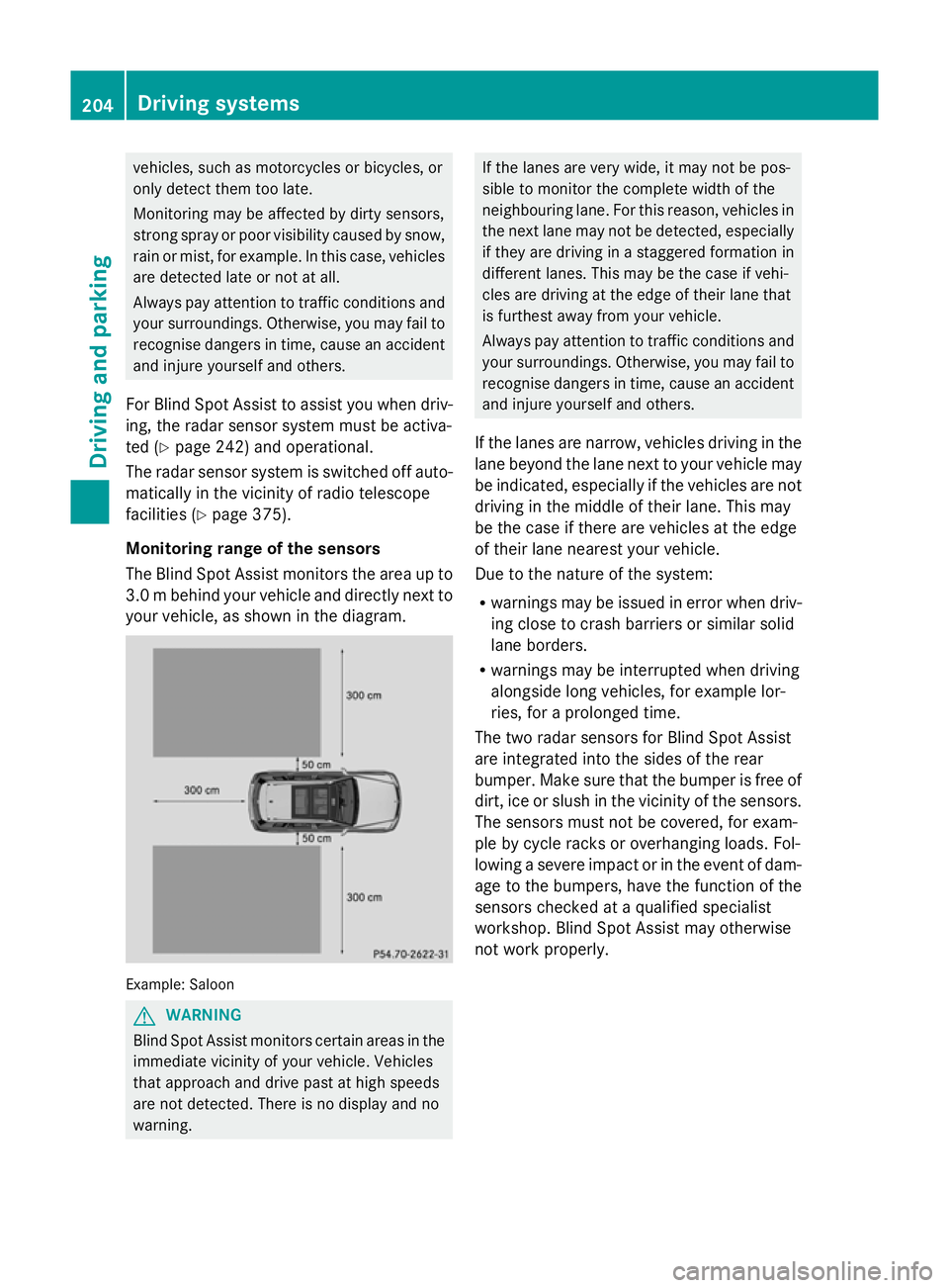
Monitoring range of the sensors
The Blind Spot Assist monitors the area up to
3.0 m behind your vehicle and directly next to
your vehicle, as shown in the diagram. Example: Saloon
G
WARNING
Blind Spot Assist monitors certain areas in the
immediate vicinity of your vehicle. Vehicles
that approach and drive past at high speeds
are not detected. There is no display and no
warning. If the lanes are very wide, it may not be pos-
sible to monitor the complete width of the
neighbouring lane. For this reason, vehicles in
the next lane may not be detected, especially
if they are driving in a staggered formation in
different lanes. This may be the case if vehi-
cles are driving at the edge of their lane that
is furthest away from your vehicle.
Always pay attention to traffic conditions and
your surroundings. Otherwise, you may fail to
recognise dangers in time, cause an accident
and injure yourself and others.
If the lanes are narrow, vehicles driving in the
lane beyond the lane next to your vehicle may
be indicated, especially if the vehicles are not
driving in the middle of their lane. This may
be the case if there are vehicles at the edge
of their lane nearest your vehicle.
Due to the nature of the system:
R warnings may be issued in error when driv-
ing close to crash barriers or similar solid
lane borders.
R warnings may be interrupted when driving
alongside long vehicles, for example lor-
ries, for a prolonged time.
The two radar sensors for Blind Spot Assist
are integrated into the sides of the rear
bumper. Make sure that the bumper is free of
dirt, ice or slush in the vicinity of the sensors.
The sensors must not be covered, for exam-
ple by cycle racks or overhanging loads. Fol-
lowing a severe impact or in the event of dam-
age to the bumpers, have the function of the
sensors checked at a qualified specialist
workshop. Blind Spot Assist may otherwise
not work properly. 204
Driving systemsDriving and parking
Page 211 of 381
detected, corrective braking may help you
avoid a collision. To support the course-cor-
recting brake application, Active Blind Spot
Assist also uses the forward-facing radar sen-
sor system. Active Blind Spot Assist supports
you from a speed of approximately 30 km/ h.
The radar sensor system is switched off auto-
matically in the vicinity of radio telescope
facilities (Y page 375).
For Active Blind Spot Assist to assist you
when driving, the radar sensor system must
be activated (Y page 242) and operational.
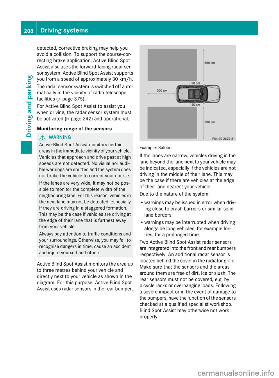
Monitoring range of the sensors G
WARNING
Active Blind Spot Assist monitors certain
areas in the immediate vicinity of your vehicle.
Vehicles that approach and drive past at high
speeds are not detected. No visual nor audi-
ble warnings are emitted and the system does
not brake the vehicle to correct your course.
If the lanes are very wide, it may not be pos-
sible to monitor the complete width of the
neighbouring lane. For this reason, vehicles in
the next lane may not be detected, especially
if they are driving in a staggered formation.
This may be the case if vehicles are driving at
the edge of their lane that is furthest away
from your vehicle.
Always pay attention to traffic conditions and
your surroundings. Otherwise, you may fail to
recognise dangers in time, cause an accident
and injure yourself and others.
Active Blind Spot Assist monitors the area up
to three metres behind your vehicle and
directly next to your vehicle as shown in the
diagram. For this purpose, Active Blind Spot
Assist uses radar sensors in the rear bumper. Example: Saloon
If the lanes are narrow, vehicles driving in the
lane beyond the lane next to your vehicle may
be indicated, especially if the vehicles are not
driving in the middle of their lane. This may
be the case if there are vehicles at the edge
of their lane nearest your vehicle.
Due to the nature of the system:
R warnings may be issued in error when driv-
ing close to crash barriers or similar solid
lane borders.
R warnings may be interrupted when driving
alongside long vehicles, for example lor-
ries, for a prolonged time.
Two Active Blind Spot Assist radar sensors
are integrated into the front and rear bumpers
respectively. An additional radar sensor is
located behind the cover in the radiator grille.
Make sure that the sensors and the areas
around them are free of dirt, ice or slush. The
rear sensors must not be covered, e.g. by
bicycle racks or overhanging loads. Following
a severe impact or in the event of damage to
the bumpers, have the function of the sensors
checked at a qualified specialist workshop.
Blind Spot Assist may otherwise not work
properly. 208
Driving systemsDriving and parking
Page 354 of 381
wheels and tyres for damage. Hidden tyre
damage could also be causing the unusual
handling characteristics. If you find no
signs of damage, have the tyres and wheels
checked at a qualified specialist workshop.
R When parking your vehicle, make sure that
the tyres do not get deformed by the kerb
or other obstacles. If it is necessary to drive
over kerbs, speed humps or similar eleva-
tions, try to do so at an obtuse angle. Oth-
erwise, the tyres, particularly the sidewalls,
can get damaged. Notes on regularly inspecting wheels
and tyres G
WARNING
Damaged tyres can cause tyre inflation pres-
sure loss. As a result, you could lose control
of your vehicle. There is a risk of accident.
Check the tyres regularly for signs of damage
and replace any damaged tyres immediately.
R Regularly check the wheels and tyres of
your vehicle for damage (e.g. cuts, punctu-
res, tears, bulges on tyres and deformation,
cracks or severe corrosion on wheels), at
least every 14days, as well as after driving
off-road or on rough roads. Damaged
wheels can cause a loss of tyre pressure.
R Regularly check the tyre tread depth and
the condition of the tread across the whole
width of the tyre (Y page 351). If neces-
sary, turn the front wheels to full lock in
order to inspect the inner side of the tyre
surface.
R All wheels must have a valve cap to protect
the valve against dirt and moisture. Do not
fit anything onto the valve other than the
standard valve cap or other valve caps
approved by Mercedes-Benz for your vehi-
cle. Do not fit any other valve caps or sys-
tems, e.g. tyre pressure monitoring sys-
tems.
R Regularly check the pressure of all the tyres
including the emergency spare wheel or the spare wheel, particularly prior to long trips,
and correct the pressure as necessary
(Y
page 353). Tyre tread
G
WARNING
Insufficient tyre tread will reduce tyre trac-
tion. The tyre is no longer able to dissipate
water. This means that on wet road surfaces,
the risk of aquaplaning increases, in particular
where speed is not adapted to suit the driving
conditions. There is a risk of accident.
If the tyre pressure is too high or too low, tyres
may exhibit different levels of wear at differ-
ent locations on the tyre tread. Thus, you
should regularly check the tread depth and
the condition of the tread across the entire
width of all tyres.
Minimum tyre tread depth for:
R summer tyres: 3 mm
R M+S tyres: 4 mm
For safety reasons, replace the tyres before
the legally prescribed limit for the minimum
tyre tread depth is reached.. Notes on selecting, fitting and replac-
ing tyres
R Only fit tyres and wheels of the same type
and make.
R Only fit tyres of the correct size onto the
wheels.
R After fitting new tyres, run them in at mod-
erate speeds for the first 100 km, as they
only reach their full performance after this
distance.
R Do not drive with tyres which have too little
tread depth, as this significantly reduces
the traction on wet roads (aquaplaning).
R Replace the tyres after six years at the lat-
est, regardless of wear. This also applies to
the emergency spare wheel/spare wheel. Operation
351Wheels and tyres Z
Page 376 of 381
R
vehicle-specific weight information can be
found on the vehicle identification plate
(Y page 364).
R only for certain countries: you can find vehi-
cle-specific vehicle data in the COC docu-
ments (CERTIFICATE OF CONFORMITY).
These documents are delivered with your
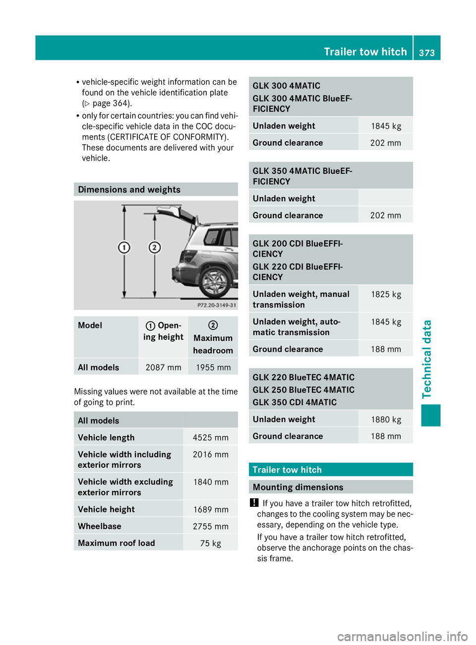
vehicle. Dimensions and weights
Model : :
Open-
ing height ;
;
Maximum
headroom All models
2087 mm 1955 mm
Missing values were not available at the time
of going to print. All models
Vehicle length
4525 mm
Vehicle width including
exterior mirrors
2016 mm
Vehicle width excluding
exterior mirrors
1840 mm
Vehicle height
1689 mm
Wheelbase
2755 mm
Maximum roof load
75 kg GLK 300 4MATIC
GLK 300 4MATIC BlueEF-
FICIENCY
Unladen weight
1845 kg
Ground clearance
202 mm
GLK 350 4MATIC BlueEF-
FICIENCY
Unladen weight
Ground clearance
202 mm
GLK 200 CDI BlueEFFI-
CIENCY
GLK 220 CDI BlueEFFI-
CIENCY
Unladen weight, manual
transmission
1825 kg
Unladen weight, auto-
matic transmission
1845 kg
Ground clearance
188 mm
GLK 220 BlueTEC 4MATIC
GLK 250 BlueTEC 4MATIC
GLK 350 CDI 4MATIC
Unladen weight
1880 kg
Ground clearance
188 mm
Trailer tow hitch
Mounting dimensions
! If you have a trailer tow hitch retrofitted,
changes to the cooling system may be nec-
essary, depending on the vehicle type.
If you have a trailer tow hitch retrofitted,
observe the anchorage points on the chas-
sis frame. Trailer tow hitch
373Technical data Z