2012 MERCEDES-BENZ GL key
[x] Cancel search: keyPage 281 of 384
weight, even when accessories for the
crossbars (e.g. ski racks, bicycle racks, etc.)
are being used. Overloading the vehicle could
result in an accident. When calculating the
weight placed on the roof please make sure
to add the weight of the crossbars, accessory
racks and the load carried together.
Always adapt your driving style to the road,
traffic and weather conditions, and drive with
added caution when the roof is loaded.
Always drive with extreme care when the
carrier is loaded. Take into consideration that
when the carrier is loaded, the handling
characteristics are different from those when
operating the vehicle without a carrier loaded.GWARNING
Do not use accessories which have not been
approved by Mercedes-Benz for use in
conjunction with these crossbars. If non-
approved accessories are used, these
accessories and/or the objects attached to
them could come loose from the vehicle,
thereby injuring you and other persons and/
or causing damage to property, including
damage to your vehicle.
! Have a second person assist you when
installing the crossbars. Otherwise, the
vehicle could be damaged.
! Objects that are attached to crossbar
system accessories must not limit or
obstruct the movement of the sliding
sunroof. Otherwise, the tilt/sliding sunroof
could be damaged when it is raised.
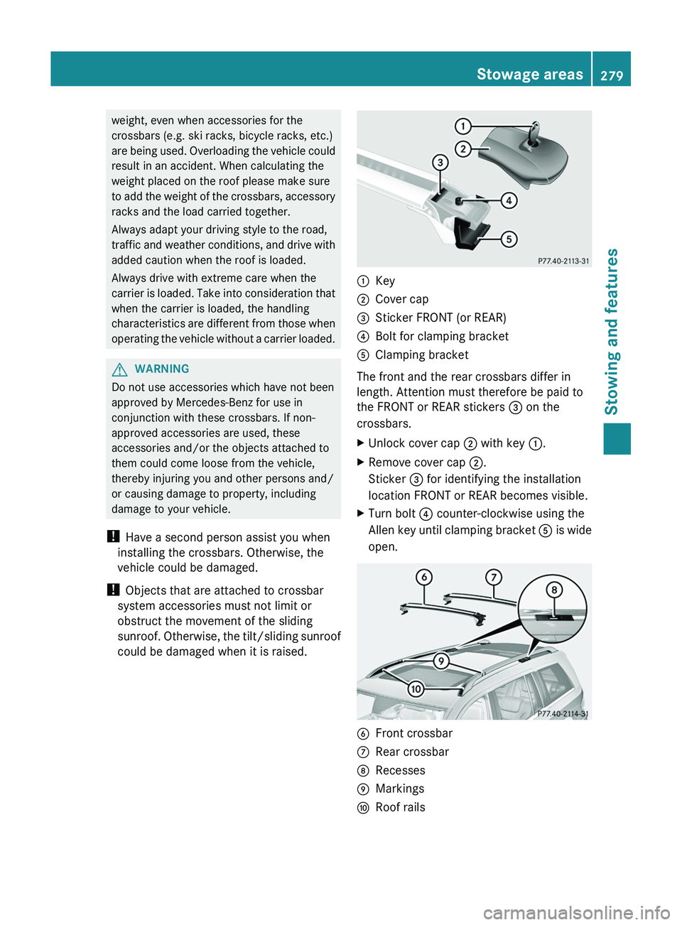
:Key;Cover cap=Sticker FRONT (or REAR)?Bolt for clamping bracketAClamping bracket
The front and the rear crossbars differ in
length. Attention must therefore be paid to
the FRONT or REAR stickers = on the
crossbars.
XUnlock cover cap ; with key :.XRemove cover cap ;.
Sticker = for identifying the installation
location FRONT or REAR becomes visible.XTurn bolt ? counter-clockwise using the
Allen key until clamping bracket A is wide
open.BFront crossbarCRear crossbarDRecessesEMarkingsFRoof railsStowage areas279Stowing and featuresZ
Page 282 of 384
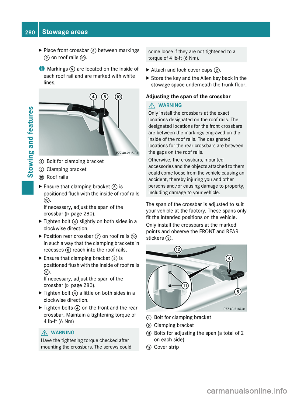
XPlace front crossbar B between markings
E on roof rails F.
i
Markings E are located on the inside of
each roof rail and are marked with white
lines.
?Bolt for clamping bracketAClamping bracketFRoof railsXEnsure that clamping bracket A is
positioned flush with the inside of roof rails
F .
If necessary, adjust the span of the
crossbar ( Y page 280).XTighten bolt ? slightly on both sides in a
clockwise direction.XPosition rear crossbar C on roof rails F
in such a way that the clamping brackets in
recesses D reach into the roof rails.XEnsure that clamping bracket A is
positioned flush with the inside of roof rails
F .
If necessary, adjust the span of the
crossbar ( Y page 280).XTighten bolt ? a little on both sides in a
clockwise direction.XTighten bolts ? on the front and the rear
crossbar. Maintain a tightening torque of
4 lb-ft (6 Nm) .GWARNING
Have the tightening torque checked after
mounting the crossbars. The screws could
come loose if they are not tightened to a
torque of 4 lb-ft (6 Nm).XAttach and lock cover caps ;.XStore the key and the Allen key back in the
stowage space underneath the trunk floor.
Adjusting the span of the crossbar
GWARNING
Only install the crossbars at the exact
locations designated on the roof rails. The
designated locations for the front crossbars
are between the markings engraved on the
inside of the roof rails. The designated
locations for the rear crossbars are between
the gaps on the roof rails.
Otherwise, the crossbars, mounted
accessories and the objects attached to them
could come loose from the vehicle causing an
accident, thereby injuring you and other
persons and/or causing damage to property,
including damage to your vehicle.
The span of the crossbar is adjusted to suit
your vehicle at the factory. These spans only
fit the intended positions on the vehicle.
Only install the crossbars at the marked
points and observe the FRONT and REAR
stickers =.
?Bolt for clamping bracketAClamping bracketGBolts for adjusting the span (a total of 2
on each side)HCover strip280Stowage areasStowing and features
Page 283 of 384
XPull out cover strip H from the groove until
bolts G become visible on both ends of the
crossbar.XTurn bolts G counter-clockwise on both
sides by approx. two turns.XPlace the crossbars on the marked points
on the roof rails.XEnsure that clamping bracket A locks
flush with the roof rails on both sides. If
necessary, pull it out or push it into
clamping brackets A.XTighten bolts G. Maintain a tightening
torque of 4 lb-ft (6 Nm) .
The width of the clamping bracket is set
correctly.GWARNING
Have the tightening torque checked after
mounting the crossbars. The screws could
come loose if they are not tightened to a
torque of 4 lb-ft (6 Nm).
XPress cover strip H into the groove of the
crossbar bit by bit.XInstall the crossbars as described
( Y page 278).
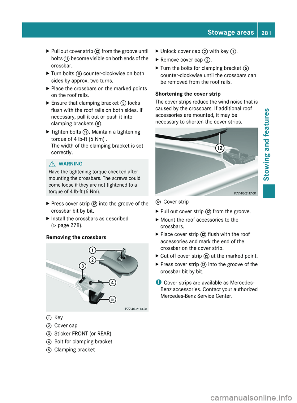
Removing the crossbars
:Key;Cover cap=Sticker FRONT (or REAR)?Bolt for clamping bracketAClamping bracketXUnlock cover cap ; with key :.XRemove cover cap ;.XTurn the bolts for clamping bracket A
counter-clockwise until the crossbars can
be removed from the roof rails.
Shortening the cover strip
The cover strips reduce the wind noise that is
caused by the crossbars. If additional roof
accessories are mounted, it may be
necessary to shorten the cover strips.
HCover stripXPull out cover strip H from the groove.XMount the roof accessories to the
crossbars.XPlace cover strip H flush with the roof
accessories and mark the end of the
crossbar on the cover strip.XCut off cover strip H at the marked point.XPress cover strip H into the groove of the
crossbar bit by bit.
i Cover strips are available as Mercedes-
Benz accessories. Contact your authorized
Mercedes-Benz Service Center.
Stowage areas281Stowing and featuresZ
Page 286 of 384
XTo close: pull out the roller sunblind using
handle = and attach arm ; to
bracket :.
The roller sunblind engages.XTo open: press release knob ? to release
the roller sunblind from bracket :.XRetract the roller sunblind by hand.
Ashtray
Ashtray in the front-compartment
center console
i You can remove the ashtray insert and
use the resulting compartment for
stowage.
! The stowage space under the ashtray is
not heat resistant. Before placing lit
cigarettes in the ashtray, make sure that
the ashtray is properly engaged. Otherwise,
the stowage space could be damaged.
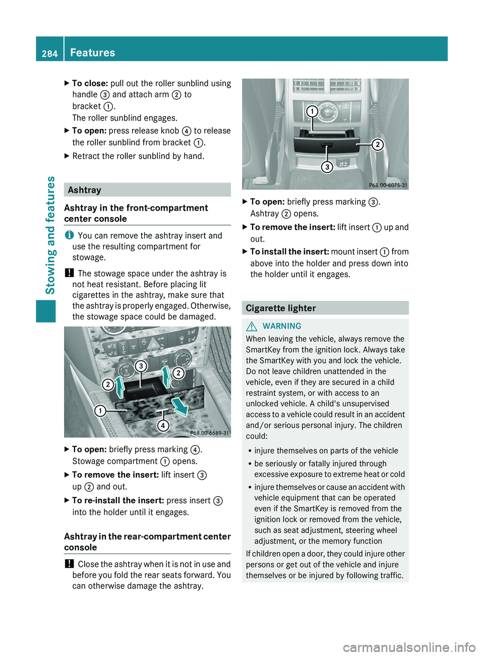
XTo open: briefly press marking ?.
Stowage compartment : opens.XTo remove the insert: lift insert =
up ; and out.XTo re-install the insert: press insert =
into the holder until it engages.
Ashtray in the rear-compartment center
console
! Close the ashtray when it is not in use and
before you fold the rear seats forward. You
can otherwise damage the ashtray.
XTo open: briefly press marking =.
Ashtray ; opens.XTo remove the insert: lift insert : up and
out.XTo install the insert: mount insert : from
above into the holder and press down into
the holder until it engages.
Cigarette lighter
GWARNING
When leaving the vehicle, always remove the
SmartKey from the ignition lock. Always take
the SmartKey with you and lock the vehicle.
Do not leave children unattended in the
vehicle, even if they are secured in a child
restraint system, or with access to an
unlocked vehicle. A child's unsupervised
access to a vehicle could result in an accident
and/or serious personal injury. The children
could:
R injure themselves on parts of the vehicle
R be seriously or fatally injured through
excessive exposure to extreme heat or cold
R injure themselves or cause an accident with
vehicle equipment that can be operated
even if the SmartKey is removed from the
ignition lock or removed from the vehicle,
such as seat adjustment, steering wheel
adjustment, or the memory function
If children open a door, they could injure other
persons or get out of the vehicle and injure
themselves or be injured by following traffic.
284FeaturesStowing and features
Page 287 of 384
Do not expose the child restraint system to
direct sunlight. The child restraint system's
metal parts, for example, could become very
hot, and the child could be burned on these
parts.GWARNING
Never touch the heating element or sides of
the lighter; they are extremely hot. Hold the
knob only.
Make sure any children traveling with you do
not injure themselves or start a fire with the
hot cigarette lighter.
! The 12 V socket in the cigarette lighter
can be used for accessories (up to a
maximum of 180 W) as long as they have
the standard socket type for cigarette
lighters. Note that the socket in the
cigarette lighter can be damaged when
connecting accessories, for example by
frequent insertion and removal or by
sockets that do not fit correctly. A damaged
socket can cause the cigarette lighter to
stop working.
! The cigarette lighter in the center console
in the front compartment is not intended
for operating the tire inflation compressor.
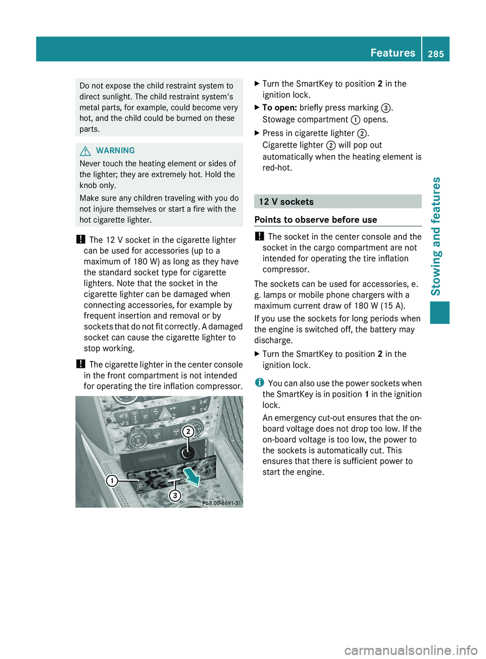
XTurn the SmartKey to position 2 in the
ignition lock.XTo open: briefly press marking =.
Stowage compartment : opens.XPress in cigarette lighter ;.
Cigarette lighter ; will pop out
automatically when the heating element is
red-hot.
12 V sockets
Points to observe before use
! The socket in the center console and the
socket in the cargo compartment are not
intended for operating the tire inflation
compressor.
The sockets can be used for accessories, e.
g. lamps or mobile phone chargers with a
maximum current draw of 180 W (15 A).
If you use the sockets for long periods when
the engine is switched off, the battery may
discharge.
XTurn the SmartKey to position 2 in the
ignition lock.
i You can also use the power sockets when
the SmartKey is in position 1 in the ignition
lock.
An emergency cut-out ensures that the on-
board voltage does not drop too low. If the
on-board voltage is too low, the power to
the sockets is automatically cut. This
ensures that there is sufficient power to
start the engine.
Features285Stowing and featuresZ
Page 294 of 384
Downloading destinations in COMAND
iInformation on the components and
operating principles of COMAND can be
found in the separate COMAND operating
instructions.
i You can only use the Destination
Download function if the vehicle is
equipped with a navigation system.
Destination Download gives you access to a
database with over 15 million points of
interest (POIs)/important destinations that
can be downloaded onto the navigation
system of your vehicle. If you know the
destination, you can download the address or
obtain the location of points of interest
(POIs)/important destinations in the
surrounding area.
You are prompted to confirm route guidance
to the address entered.
XSelect Yes with the = or ; buttons
on COMAND.XPress the 9 button on COMAND to
confirm.
The system calculates the route and
subsequently starts the route guidance with
the address entered.
i If you select No, the address can be stored
in the address book.
i The Destination Download function is
available if the corresponding mobile
phone network is available and data
transfer is possible.
Route Assistance
This service is part of the mbrace PLUS
Package and cannot be purchased
separately.
i You can also use the Route Assistance
function if your vehicle is not equipped with
a navigation system.
Within the framework of this service, you
receive a professional and reliable form of
navigation support without having to leave
your vehicle.
The customer service representative
determines a suitable driving route based on
your current vehicle position and the desired
destination and guides you live through the
current sections of the route.
Search & Send
"Search & Send" is a destination entry
service. You can find further information on
"Search & Send" in the separate COMAND
operating instructions.
Vehicle remote opening
If you have unintentionally locked your
vehicle (e.g. the SmartKey is still in the
vehicle) and a replacement SmartKey is not
available, the vehicle can be opened by a
Mercedes-Benz Customer Assistance Center.
The vehicle can be opened remotely up to four
days after the ignition was last switched off.
XContact the following service hotlines:
R USA: Mercedes-Benz Customer
Assistance Center under 1-800-FOR-
MERCedes(1-800-367-6372) or
1-888-990-9007
R Canada: Customer Service at
1-888-923-8367
You will be asked for your password.XReturn to your vehicle at the time agreed
upon with the Mercedes-Benz Customer
Assistance Center.XPull the tailgate handle for at least 20
seconds until the indicator lamp in the SOS
button ( Y page 288) flashes.
The Connecting Call message appears
on the multifunction display.
Alternatively, the vehicle can also be opened
via the Internet or an iPhone in the "Owners
Online" section using your ID number and
password 35
.
35 USA only.292FeaturesStowing and features
Page 296 of 384

1. This device must not cause harmful
interference, and
2. this device must withstand any
interference received, including
interference that may cause undesired
operation.
Any unauthorized modification to this
device could void the user's authority to
operate the equipment.
i Canada only:
This device complies with RSS-210 of
Industry Canada. Operation is subject to
the following two conditions:
1. This device must not cause harmful
interference, and
2. this device must withstand any
interference received, including
interference that may cause undesired
operation.
Any unauthorized modification to this
device could void the user's authority to
operate the equipment.
Programming the integrated garage
door opener on the rear-view mirror
Programming
GWARNING
Only press the transmitter button on the
integrated garage door opener if there are no
persons or objects present within the sweep
of the garage door. People could otherwise be
injured by the movement of the door.
Integrated garage door opener on the rear-view
mirror
Garage door remote control A is not part of
this integrated garage door opener.
i To achieve the best result, insert new
batteries in garage door remote control
A before programming.
XBefore programming for the first time, clear
the memory of the integrated garage door
opener ( Y page 296).XTurn the SmartKey to position 2 in the
ignition lock.XPress and hold one of transmitter
buttons ; to ? on the integrated garage
door opener.
Indicator lamp : starts to flash yellow
after a short period.
i Indicator lamp : flashes yellow
immediately after the transmitter button
has been stored for the first time. If the
transmitter button has already been
programmed, indicator lamp : does not
flash yellow until 10 seconds have elapsed.
XRelease the transmitter button.XPoint transmitter button B of garage door
remote control A towards the transmitter
buttons on the rear-view mirror at a
distance of 2 to 8 inches (5 to 20 cm).
i The distance required between garage
door remote control A and the integrated
garage door opener depends on the system
of the garage door drive. You might require
several attempts. You should test every
294FeaturesStowing and features
Page 297 of 384

position for at least 25 seconds before
trying another position.XPress and hold transmitter button B on
garage door remote control A until
indicator lamp : lights up green.
Programming is complete if indicator
lamp : lights up or flashes green.XRelease transmitter button ;, = or ? on
the integrated garage door opener and the
transmitter button on garage door remote
control B.
If indicator lamp : lights up red:
XRepeat the programming procedure for the
transmitter button. When doing so, vary the
distance between the garage door remote
control and the rear-view mirror.
i If the indicator lamp flashes green after
successful programming, the garage door
system is operating on a rolling code. After
programming, you must synchronize the
garage door opener integrated in the rear-
view mirror with the receiver of the garage
door system.
Synchronizing the rolling code
Your vehicle must be within range of the
garage or gate opener drive. Make sure that
neither your vehicle nor any persons/objects
are present within the sweep of the door or
gate.
Observe the safety notes when performing
the rolling code synchronization.
XTurn the SmartKey to position 2 in the
ignition lock.XPress the programming button of the door
or gate drive (see the door or gate drive
operating instructions, e.g. under
"Programming of additional remote
controls").
i You now normally have 30 seconds to
initiate the next step.
XPress the previously programmed
transmitter button of the HomeLink ®integrated garage door opener repeatedly
in succession until the door opens.
The rolling code synchronization is then
complete.
Notes on programming the remote
control
Canadian radio frequency laws require a
"break" (or interruption) of the transmission
signals after broadcasting for a few seconds.
These signals may not therefore last long
enough for the integrated garage door opener
to recognize the signal during programming.
Comparable with Canadian law, some U.S.
garage door openers also have a built-in
"interruption".
If you live in Canada or have difficulties
programming the garage door opener
(regardless of where you live) when using the
programming steps (see above), proceed as
follows:
XPress and hold one of transmitter
buttons ; to ? of the integrated garage
door opener.
Indicator lamp : starts to flash yellow
after a short period.XRelease the transmitter button.XPress transmitter button B of the garage
door remote control and hold for two
seconds, then release for two seconds,
then press again and hold for two seconds.XRepeat this sequence on transmitter
button B of the garage door remote
control until indicator lamp : is green.
Repeat the process if indicator lamp :
turns red.XContinue with the other programming
steps (see above).
Problems when programming
If you are experiencing problems
programming the integrated garage door
opener on the rear-view mirror, take note of
the following instructions:
R check the transmission frequency of
garage door remote control A (usually
Features295Stowing and featuresZ