2012 MERCEDES-BENZ G-CLASS SUV turn signal
[x] Cancel search: turn signalPage 195 of 357
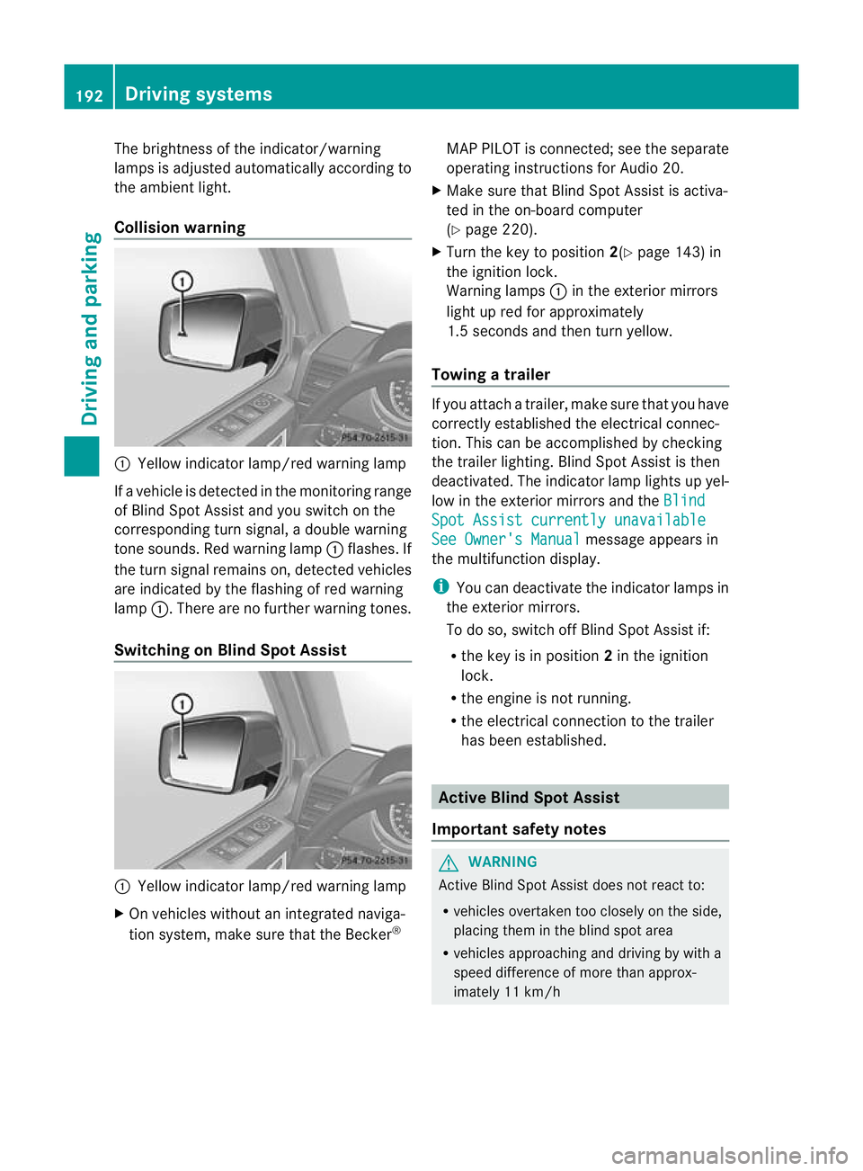
The brightness of the indicator/warning
lamps is adjusted automatically according to
the ambient light.
Collision warning
:
Yellow indicator lamp/red warning lamp
If a vehicle is detected in the monitoring range
of Blind Spot Assist and you switch on the
corresponding turn signal, a double warning
tone sounds. Red warning lamp :flashes. If
the turn signal remains on, detected vehicles
are indicated by the flashing of red warning
lamp :.There are no further warning tones.
Switching on Blind Spot Assist :
Yellow indicator lamp/red warning lamp
X On vehicles without an integrated naviga-
tion system, make sure that the Becker ®MAP PILOT is connected; see the separate
operating instructions for Audio 20.
X Make sure that Blind Spot Assist is activa-
ted in the on-board computer
(Y page 220).
X Turn the key to position 2(Ypage 143) in
the ignition lock.
Warning lamps :in the exterior mirrors
light up red for approximately
1.5 seconds and then turn yellow.
Towing atrailer If you attach a trailer, make sure tha
tyou have
correctly established the electrical connec-
tion. This can be accomplished by checking
the trailer lighting. Blind Spot Assist is then
deactivated. The indicator lamp lights up yel-
low in the exterior mirrors and the Blind Spot Assist currently unavailable
See Owner's Manual message appears in
the multifunction display.
i You can deactivate the indicator lamps in
the exterior mirrors.
To do so, switch off Blind Spot Assist if:
R the key is in position 2in the ignition
lock.
R the engine is not running.
R the electrical connection to the trailer
has been established. Active Blind Spot Assist
Important safety notes G
WARNING
Active Blind Spot Assist does not react to:
R vehicles overtaken too closely on the side,
placing them in the blind spot area
R vehicles approaching and driving by with a
speed difference of more than approx-
imately 11 km/h 192
Driving systemsDriving and parking
Page 196 of 357

In such situations, Active Blind Spot Assist
cannot warn you or intervene. There is a risk
of an accident.
Always observe the traffic conditions care-
fully, and maintain a safe lateral distance.
Active Blind Spot Assist is only an aid.Itm ay
fail to detect some vehicles and is no substi-
tute for attentive driving.
In particular, the detection of obstacles can
be impaired if:
R there is dirt on the sensors or anything else
covering the sensors.
R visibility is poor, e.g .due to fog, heavy rain
or snow.
R there is a narrow vehicl etravelling in front,
e.g. a motorcycle or bicycle.
R the road has very wide lanes.
R the road has narrow lanes.
R you are not driving in the middle of the lane.
R there are barriers or other road boundaries.
General notes Active Blind Spot Assist uses a rada
rsensor
system to monitor the side areas of your vehi-
cle which are behind the driver. Awarning
display in the exterior mirrors draws your
attentio nto vehicles detected in the moni-
tored area. If you then switch on the corre-
sponding turn signal to change lane, you will
also receive an optical and audible collision
warning. If a risk of lateral collision is detec-
ted, corrective braking may help you avoid a
collision. To support the course-correcting
brake application, Active Blind Spot Assist
also uses the forward-facing radar sensor sys-
tem.
Active Blind Spot Assist supports you from a
speed of approximately 30 km/h.
Monitoring range G
WARNING
Active Blind Spot Assist monitors certain
areas in the immediate vicinity of your vehicle. Vehicles that approach and drive past at high
speeds are not detected. No visual nor audi-
ble warnings are emitted and the system does
not brake the vehicle to correct your course.
If the lanes are very wide, it may not be pos-
sible to monitor the complete width of the
neighbouring lane. For this reason, vehicles in
the next lane may not be detected, especially
if they are driving in a staggered formation.
This may be the case if vehicles are driving at
the edge of their lane that is furthest away
from your vehicle.
Always pay attention to traffic conditions and
your surroundings. Otherwise, you may fail to
recognise dangers in time, cause an accident
and injure yourself and others.
Active Blind Spot Assist monitors the area up
to 3.0 m behind your vehicle and directly next
to your vehicle, as shown in the diagram. For
this purpose, Active Blind Spot Assist uses
radar sensors in the rear bumper.
If the lanes are narrow, vehicles driving in the
lane beyond the lane next to your vehicle may
be indicated, especially if the vehicles are not
driving in the middle of their lane. This may
be the case if there are vehicles at the edge
of their lane nearest your vehicle. Driving systems
193Driving and parking Z
Page 197 of 357

Due to the nature of the system:
R
warnings may be issued in error when driv-
ing close to crash barriers or simila rsolid
lane borders.
R warnings may be interrupted when driving
alongside particularly long vehicles, for
example lorries, for a prolonged time.
Two Active Blind Spot Assist radar sensors
are integrated into the front and rear bumpers
respectively. An additional radar sensor is
located behind the cover in the radiator grille.
Make sure that the bumpers and the cover in
the radiator grille are free of dirt, ice or slush.
The rear sensors must not be covered, e.g. by
bicycle racks or overhanging loads. Following
a severe impact or in the event of damage to
the bumpers, have the function of the radar
sensors checked at a qualified specialist
workshop. Active Blind Spot Assist may oth-
erwise no longer work properly.
Indicator and warning display G
WARNING
Active Blind Spot Assist is not active at speeds
below 30 km/h. The indicator lamps in the
exterior mirrors are yellow .Vehicles in the
monitoring range are then not indicated.
Always pay attention to traffic conditions and
your surroundings. Otherwise, you may fail to
recognise dangers in time and cause an acci-
dent and injure yourself and others. :
Yellow indicator lamp/red warning lamp
When Active Blind Spot Assist is activated,
indicator lamp :in the exterior mirrors lights up yellow at speeds of up to 30 km/h. At
speeds above 30 km/h, the indicator lamp
goes out and Active Blind Spot Assist is
operational.
If a vehicle is detected within the monitoring
range of Blind Spot Assist at speeds above
30 km/h, warning lamp :on the corre-
sponding side lights up red. This warning
always occurs when a vehicle enters the blind
spot monitoring range from behind or from
the side. When you overtake a vehicle, the
warning only occurs if the difference in speed
is less than 12 km/h.
The yellow indicator lamp goes out if reverse
gear is engaged. Active Blind Spot Assist is
then no longer active.
The brightness of the indicator/warning
lamps is adjusted automatically according to
the ambient light.
Visual and acoustic collision warning When you switch on the turn signals to
change lanes and a vehicle is detected in the
side monitoring range, you receive a visual
and acoustic collision warning. You then hear
a double warning tone and red warning
lamp
:flashes. If the turn signal remains on,
detected vehicles are indicated by the flash-
ing of red warning lamp :.There are no fur-
ther warning tones. 194
Driving systemsDriving and parking
Page 237 of 357
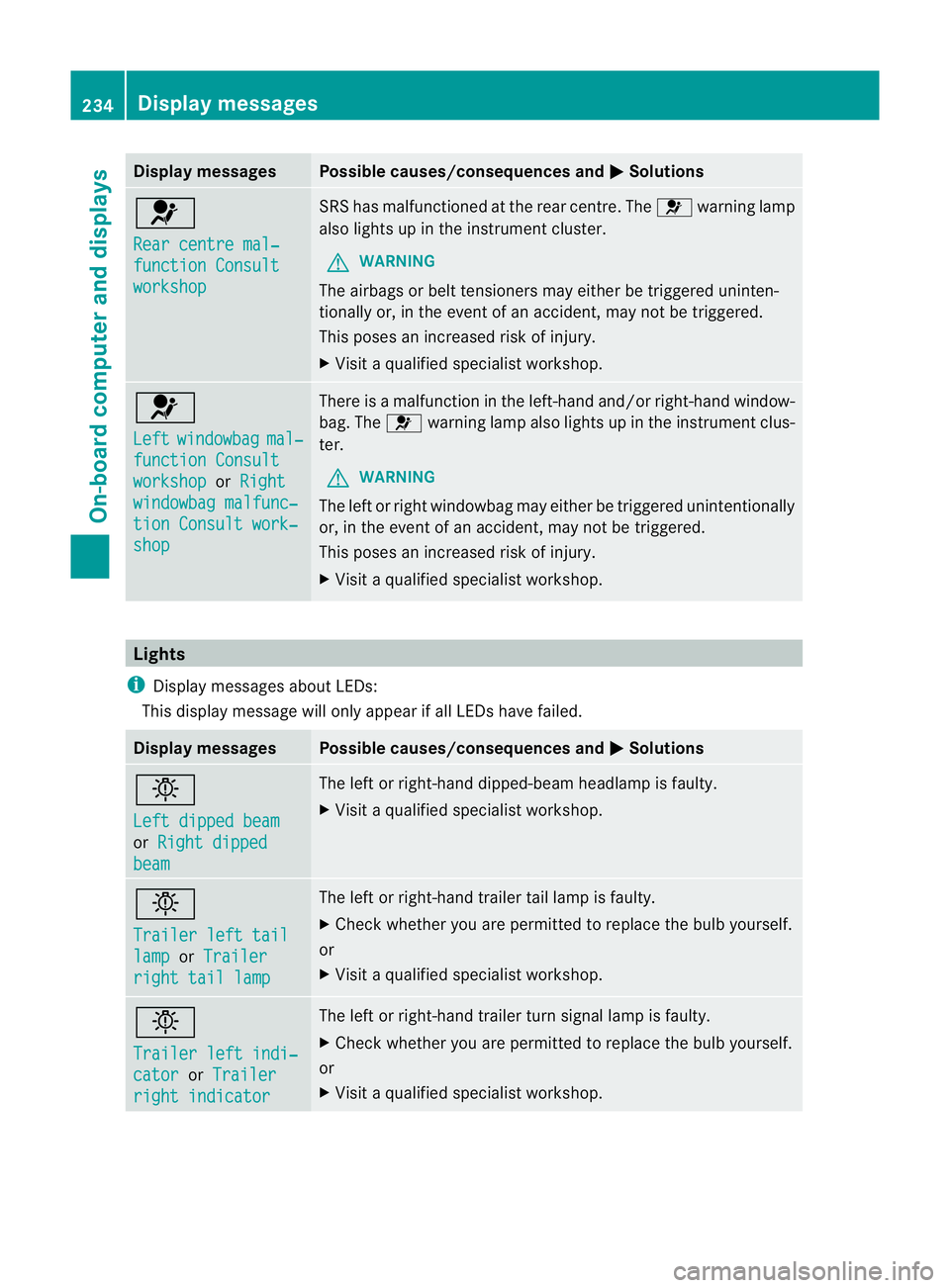
Display messages Possible causes/consequences and
M Solutions
6
Rear centre mal‐
function Consult
workshop SRS has malfunctioned at the rear centre. The
6warning lamp
also lights up in the instrumen tcluster.
G WARNING
The airbags or belt tensioners may either be triggered uninten-
tionally or, in the even tofanaccident, may not be triggered.
This poses an increased ris kofinjury.
X Visi taqualified specialist workshop. 6
Left
windowbag mal‐
function Consult
workshop or
Right windowbag malfunc‐
tion Consult work‐
shop There is a malfunction in the left-hand and/or right-hand window-
bag. The
6warning lamp also lights up in the instrument clus-
ter.
G WARNING
The left or right windowbag may either be triggered unintentionally
or, in the event of an accident, may not be triggered.
This poses an increased risk of injury.
X Visit a qualified specialist workshop. Lights
i Display messages about LEDs:
This display message will only appear if all LEDs have failed. Display messages Possible causes/consequences and
M Solutions
b
Left dipped beam
or
Right dipped beam The left or right-hand dipped-beam headlamp is faulty.
X
Visit a qualified specialist workshop. b
Trailer left tail
lamp or
Trailer right tail lamp The left or right-hand trailer tail lamp is faulty.
X
Check whether you are permitted to replace the bulb yourself.
or
X Visit a qualified specialist workshop. b
Trailer left indi‐
cator or
Trailer right indicator The left or right-hand trailer turn signal lamp is faulty.
X
Check whether you are permitted to replace the bulb yourself.
or
X Visit a qualified specialist workshop. 234
Display messagesOn-board computer and displays
Page 238 of 357
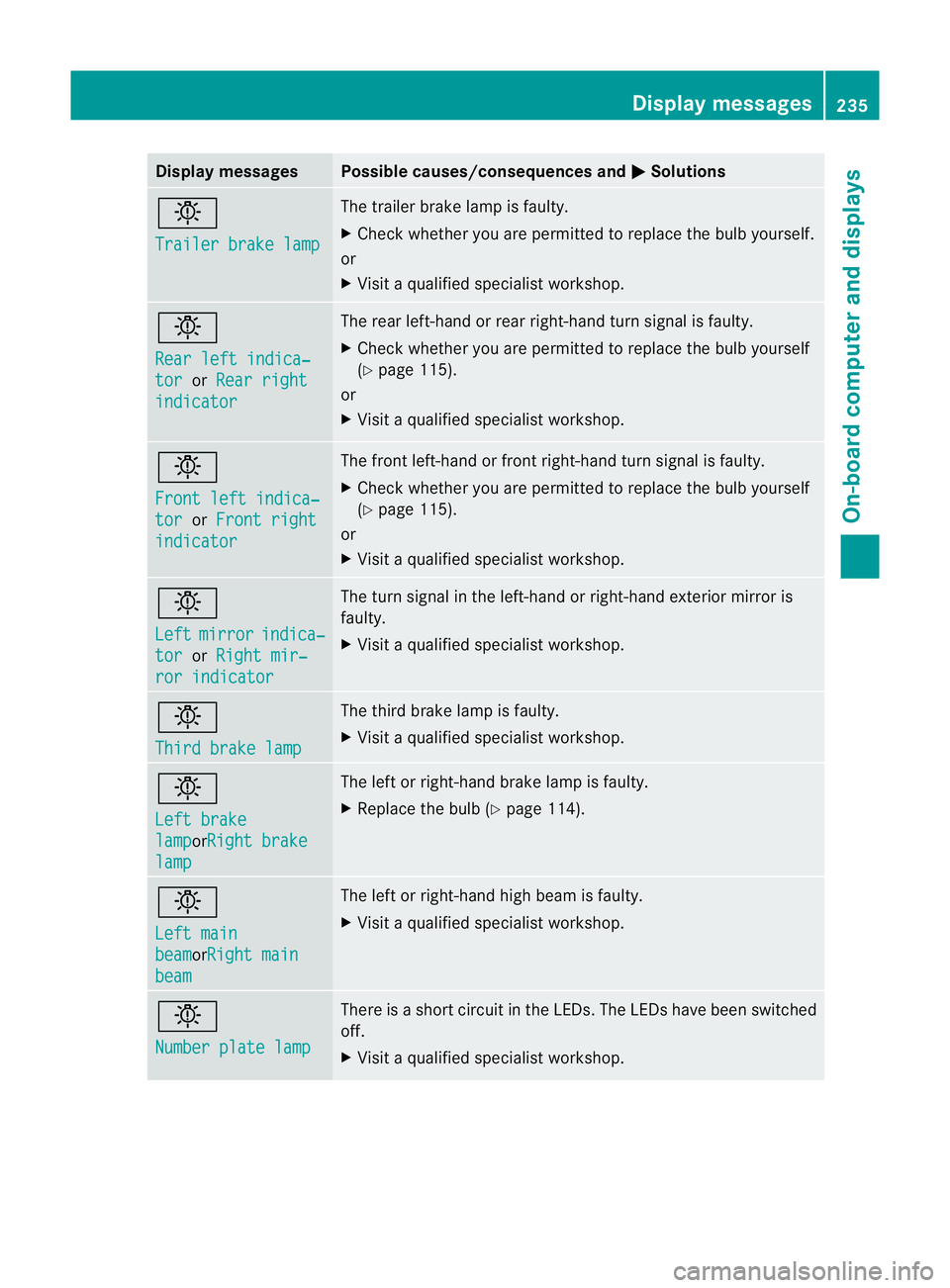
Display messages Possible causes/consequences and
M Solutions
b
Trailer brake lamp The trailer brake lamp is faulty.
X
Chec kwhether you are permitted to replace the bulb yourself.
or
X Visit a qualified specialist workshop. b
Rear left indica‐
tor or
Rear right indicator The rear left-hand or rear right-hand turn signal is faulty.
X
Check whether you are permitted to replace the bulb yourself
(Y page 115).
or
X Visit a qualified specialist workshop. b
Front left indica‐
tor or
Front right indicator The front left-hand or front right-hand turn signal is faulty.
X
Check whether you are permitted to replace the bulb yourself
(Y page 115).
or
X Visit a qualified specialist workshop. b
Left
mirror indica‐
tor or
Right mir‐ ror indicator The turn signal in the left-hand or right-hand exterior mirror is
faulty.
X
Visit a qualified specialist workshop. b
Third brake lamp The third brake lamp is faulty.
X
Visit a qualified specialist workshop. b
Left brake
lamp orRight brake
lamp The left or right-hand brake lamp is faulty.
X
Replace the bulb (Y page 114). b
Left main
beam orRight main
beam The left or right-hand high beam is faulty.
X
Visit a qualified specialist workshop. b
Number plate lamp There is a short circuit in the LEDs. The LEDs have been switched
off.
X Visit a qualified specialist workshop. Display messages
235On-board computer and displays Z
Page 254 of 357
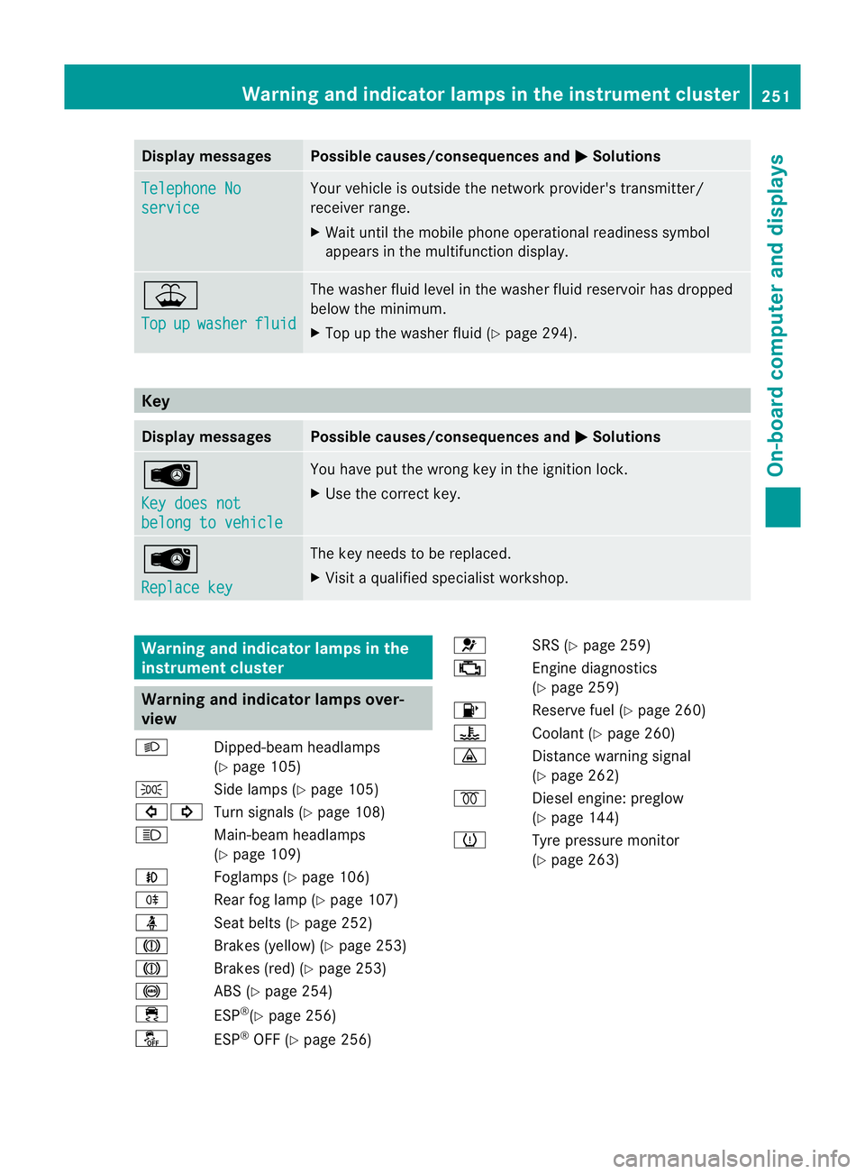
Display messages Possible causes/consequences and
M Solutions
Telephone No
service Your vehicle is outside the network provider's transmitter/
receiver range.
X
Wait until the mobile phone operational readiness symbol
appears in the multifunction display. ¥
Top
up washer fluid The washer fluid level in th
ewasher fluid reservoir has dropped
below the minimum.
X Top up the washe rfluid (Y page 294). Key
Displa
ymessages Possible causes/consequences and
M Solutions
Â
Key does not
belong to vehicle You have put the wrong key in the ignitio
nlock.
X Use the correct key. Â
Replace key The key needs to be replaced.
X Visit a qualified specialist workshop. Warning and indicator lamps in the
instrument cluster Warning and indicator lamps over-
view
L Dipped-beam headlamps
(Ypage 105)
T Side lamps (Y page 105)
#! Turn signals (Y page 108)
K Main-beam headlamps
(Ypage 109)
N Foglamps (Y page 106)
R Rear fog lamp (Y page 107)
ü Seat belts (Y page 252)
J Brakes (yellow) (Y page 253)
J Brakes (red) (Y page 253)
! ABS (Ypage 254)
÷ ESP®
(Y page 256)
å ESP®
OFF (Y page 256) 6
SRS (Ypage 259)
; Engine diagnostics
(Ypage 259)
8 Reserve fuel (Y page 260)
? Coolant (Ypage 260)
· Distance warning signal
(Ypage 262)
% Diesel engine: preglow
(Ypage 144)
h Tyre pressure monitor
(Ypage 263) Warning and indicator lamps in the instrument cluster
251On-board computer and displays Z
Page 285 of 357
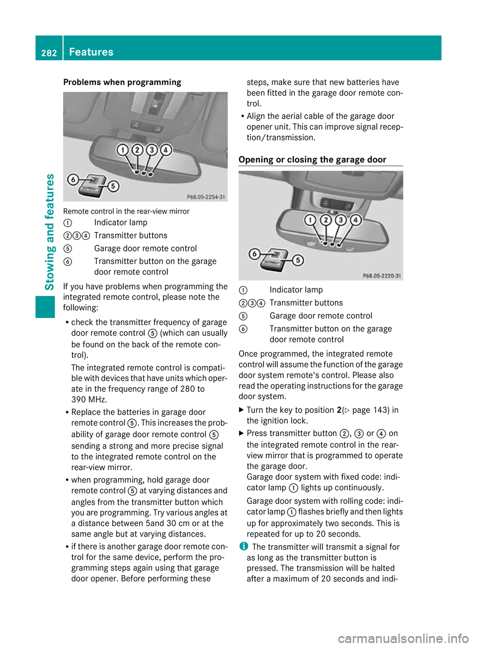
Problems when programming
Remote control in the rear-view mirror
:
Indicator lamp
;=? Transmitter buttons
A Garage door remote control
B Transmitter button on the garage
door remote control
If you have problems when programming the
integrated remote control, please note the
following:
R check the transmitter frequency of garage
door remote control A(which can usually
be found on the back of the remote con-
trol).
The integrated remote control is compati-
ble with devices that have units which oper-
ate in the frequency range of 280 to
390 MHz.
R Replace the batteries in garage door
remote control A.This increases the prob-
ability of garage door remote control A
sending a strong and more precise signal
to the integrated remote control on the
rear-view mirror.
R when programming, hold garage door
remote control Aat varying distances and
angles from the transmitter button which
you are programming. Try various angles at
a distance between 5and 30 cm or at the
same angle but at varying distances.
R if there is another garage door remote con-
trol for the same device, perform the pro-
gramming steps again using that garage
door opener. Before performing these steps, make sure that new batteries have
been fitted in the garage door remote con-
trol.
R Align the aerial cable of the garage door
opener unit. This can improve signal recep-
tion/transmission.
Opening or closing the garage door :
Indicator lamp
;=? Transmitter buttons
A Garage door remote control
B Transmitter button on the garage
door remote control
Once programmed, the integrated remote
control will assume the function of the garage
door system remote's control. Please also
read the operating instructions for the garage
door system.
X Turn the key to position 2(Ypage 143) in
the ignition lock.
X Press transmitter button ;,=or? on
the integrated remote control in the rear-
view mirror that is programmed to operate
the garage door.
Garage door system with fixed code: indi-
cator lamp :lights up continuously.
Garage door system with rolling code: indi-
cator lamp :flashes briefly and then lights
up for approximately two seconds. This is
repeated for up to 20 seconds.
i The transmitter will transmit a signal for
as long as the transmitter button is
pressed. The transmission will be halted
after a maximum of 20 seconds and indi- 282
FeaturesStowing and features
Page 320 of 357
Towing the vehicle with both axles on
the ground
It is important tha tyou observe the safety
instructions when towing away your vehicle
(Y page 315).
X Switch on the hazard warning lamps
(Y page 109).
i In order to signal a change of direction
when towing the vehicle with the hazard
warning lamps switched on, use the com-
bination switch as usual.Int his case, only
the turn signals for the desired direction
flash. When you reset the combination
switch, the hazard warning lamps start
flashing again.
X Turn the key to position 2in the ignition
lock (Y page 143).
X When the vehicle is stationary, depress the
brake pedal and keep it depressed.
X Shift the transfer case to neu-
tral(Y page 203).
X Shift the automatic transmission to posi-
tion N.
X Release the brake pedal.
X Release the parking brake (Y page 164).
i The transmission can only change gear
when the battery has sufficient charge.
If you cannot move the selector lever to N,
you must remove the propeller shafts to the
driven axles. Transporting the vehicle
! Only lash the vehicle down by the wheels
or wheel rims, not by parts of the vehicle
such as axle or steering components. Oth-
erwise, the vehicle could be damaged.
Use the towing eyes to pull the vehicle if it
needs to be transported on a trailer or trans-
porter (Y page 316).
X Apply the parking brake.
X Turn the key to position 2in the ignition
lock (Y page 143). X
Move the selector lever to N.
X Shift the transfer case to neu-
tral(Y page 203).
X Secure the towing cable to the towing eyes
(Y page 316).
X Make sure that the vehicle cannot roll
away.
X Release the parking brake.
X Load the vehicle onto the transporter.
As soon as the vehicle is loaded:
X Apply the parking brake.
X Shift the automatic transmission to posi-
tion P.
X Turn the key to position 0in the ignition
lock (Y page 143) and remove it.
X Secure the vehicle. Recovering
avehicle that has become
stuck
! When recovering a trapped vehicle, do not
jerk the vehicle or pull it at an angle. If the
tractive power is too high, the vehicles
could be damaged.
If the drive wheels get trapped on loose or
muddy ground, recover th evehicle with the
utmost care, especially so if the vehicle is
laden.
Never attempt to recover a vehicle with a
trailer attached.
Pull out the vehicle backwards, if possible,
using the tracks it made when it became
stuck. Towing in the event of malfunctions
General notes !
If you are removing the propeller shaft,
use M10 nuts as spacers on the M8 bolts
and secure them with M8 nuts.
New self-locking nuts must be used when
the propeller shafts are refitted. Towing and tow-starting
317Breakdown assistance Z