2012 MERCEDES-BENZ G-CLASS SUV clock
[x] Cancel search: clockPage 211 of 357
Trailer power supply
! You can connect accessories with a max-
imum power consumption of 180 W to the
permanent powe rsupply.
You must no tcharge a trailer battery using
the power supply.
The trailer socket of your vehicle is equipped
at the factory with apermanen tpower supply.
The permanent power supply is supplied via
trailer socket pin 9.
You can find more information about fitting
the trailer electrics at a qualified specialist
workshop. Trailer with 7-pin connector
General notes You can make a connection to the 13-pin
socket on the ball coupling using an adapter
or, if necessary, an adapter cable. Both can
be obtained at a qualified specialist work-
shop.
Fitting the adapter !
Make sure that there is sufficient cable
play so that the cable cannot become
detached when cornering. X
Open the socket cover.
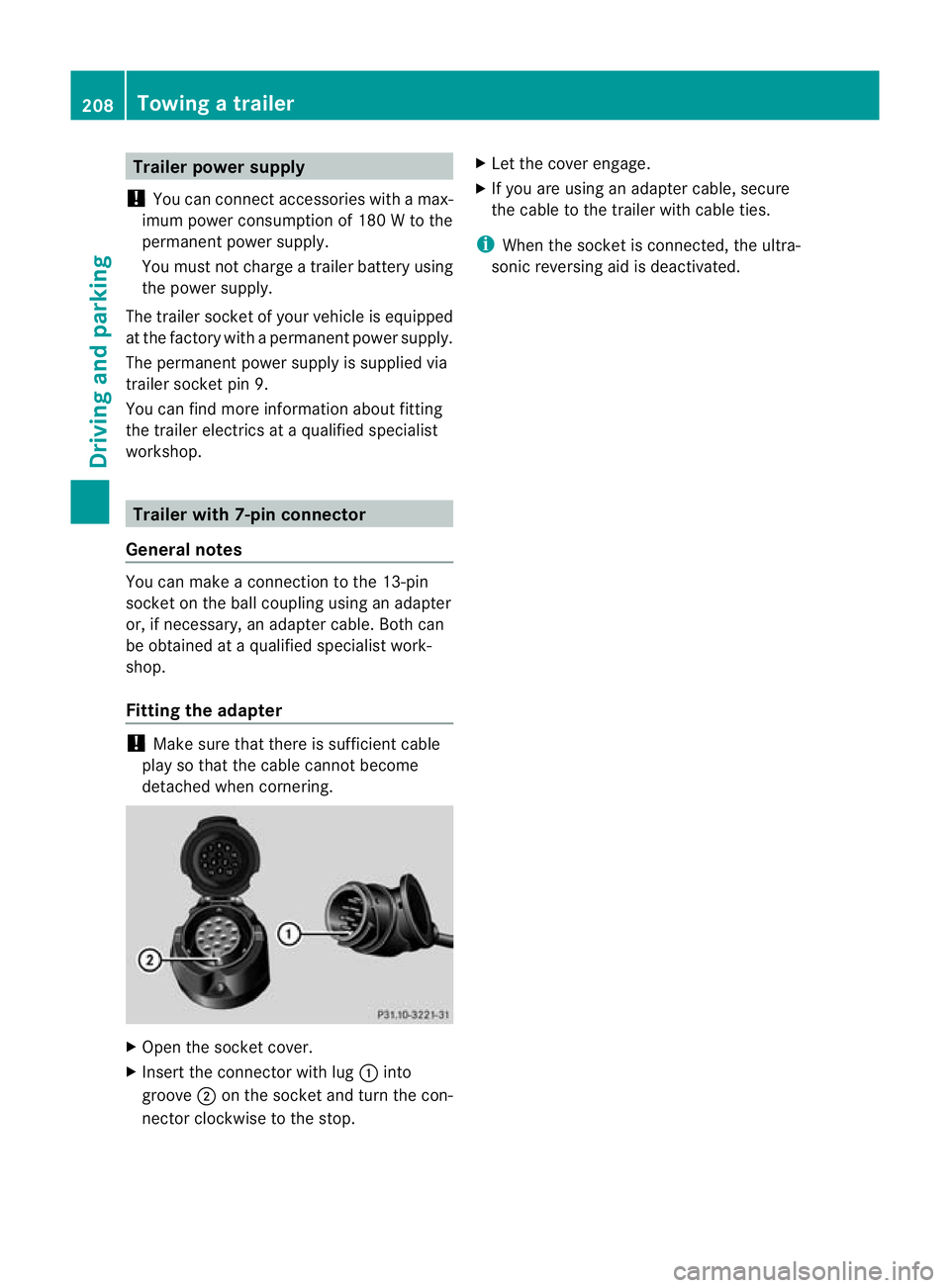
X Insert the connector with lug :into
groove ;on the socket and turn the con-
nector clockwise to the stop. X
Let the cover engage.
X If you are using an adapter cable, secure
the cable to the trailer with cable ties.
i When the socket is connected, the ultra-
sonic reversing aid is deactivated. 208
Towing
atrailerDriving an d parking
Page 215 of 357

=
Rev counter (Y page 212)
? Coolan ttemperature (Y page 212)
A Fuel gauge
B Instrument cluster lighting (Y page 212)Instrument cluster lighting
The lighting in the instrument cluster, in the
displays and the controls in the vehicle inte-
rior can be adjusted using the brightness con-
trol knob.
The brightness control knob is located on the
bottom left of the instrument cluster
(Y page 211).
X Turn the brightness control knob clockwise
or anti-clockwise.
If the light switch is set to Ã,Tor
L, the brightness is dependen tupon
the brightness of the ambient light.
i The light senso rinthe instrumentc luster
automatically controls the brightness of
the multifunction display.
In daylight, the displays in the instrument
cluster are not illuminated. Displaying the coolant temperature
The coolan ttemperature gauge is in the
instrument cluster on the right-hand side
(Y page 211).
The reading may rise up to 120 †undernor-
mal driving conditions if the coolant has been
filled correctly.
At high outside temperatures and when driv-
ing uphill, the coolant temperature may rise
to the end of the scale. Rev counter
! Do not drive in the overrevving range.
Doing so will damage the engine.
The red band in the rev counter indicates the
engine's overrevving range. The fuel supply is interrupted to protec
tthe
engine when the red band is reached. Outside temperature display
G
WARNING
At temperatures just above freezing point, the
street may be icy, especially in wooded areas
or on bridges. If you do not adapt your driving
style to the conditions, the vehicle could skid.
For this reason, adapt your driving style and
speed to the weather conditions.
The outside temperature displayi s in the mul-
tifunction display (Y page 214).
Changes in the outside temperature are dis-
played after a short delay. Speedometer with segments
The segments in the speedometer indicate
which speed range is available.
R Cruise control activated (Y page 173):
The segments light up from the stored
speed to the maximum speed.
R Variable SPEEDTRONIC activated
(Y page 178):
The segments light up from the start of the
scale to the selected limit speed.
R DISTRONIC PLUS activated (Y page 184):
One or two segments in the set speed
range light up.
R DISTRONIC PLUS detects avehicle in front:
The segments between the speed of the
vehicle in fron tand the stored speed light
up. 212
Displays and operationOn-board computer and displays
Page 270 of 357
If the rear bench seat is not occupied:
X
insert the belt tongue on the outer seat
belts into the buckle of opposite seat
belt :.
X secure the load with sufficiently strong and
wear-resistant lashing material.
X pad sharp edges for protection.
i Lashing material that has been checked
in accordance with applicable standards is
available at any qualified specialist work-
shop. Stowage areas
Stowage compartments
Important safety notes G
WARNING
The stowage compartments must be closed
when items are stored in them. Luggage nets
are not designed to secure heavy items of
luggage.
You or other vehicle occupants could be
injured by objects being thrown around if you:
R brake sharply
R change direction suddenly
R are involved in an accident
Sharp-edged and fragile objects must not be
placed in the luggage net.
Do not place hard objects in the map pockets.
Objects must not protrude from the map
pockets. Front stowage compartments Glove compartment
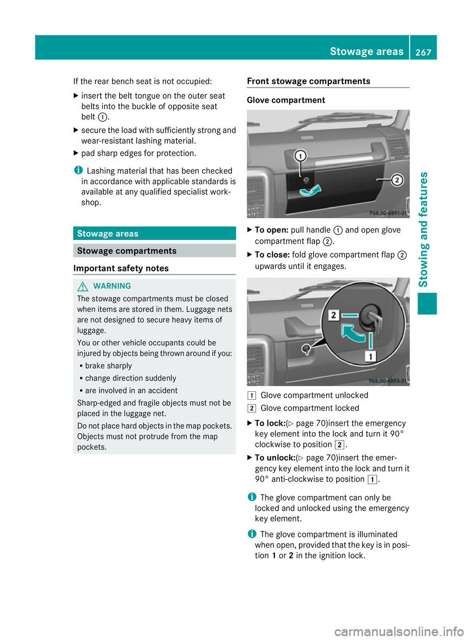
X
To open: pull handle :and open glove
compartment flap ;.
X To close: fold glove compartment flap ;
upwards until it engages. 1
Glove compartment unlocked
2 Glove compartment locked
X To lock:(Y page 70)insert the emergency
key element into the lock and turn it 90°
clockwise to position 2.
X To unlock:(Y page 70)insert the emer-
gency key element into the lock and turn it
90° anti-clockwise to position 1.
i The glove compartment can only be
locked and unlocked using the emergency
key element.
i The glove compartment is illuminated
when open, provided that the key is in posi-
tion 1or 2in the ignition lock. Stowage areas
267Stowing and features Z
Page 296 of 357
X
If the engine is at normal operating tem-
perature: repeat the measuremen tafter
about five minutes.
X If the engine is not at normal operating
temperature: (e.g. if the engine was only
started briefly) repeat the measurement
after about 30 minutes.
If the Engine oil level Not when engine on message appears:
X Switch off the engine.
X If the engine is at normal operating tem-
perature: wait about five minutes before
carrying out the measurement.
X If the engine is not at normal operating
temperature: e.g. if the engine was only
started briefly, wait approximately
30 minutes before carrying out the meas-
urement.
i If you wish to cancel the measurement,
press the *or& button on the mul-
tifunction steering wheel.
Adding engine oil H
Environmental note
When topping up the oil, take care not to spill
any. If oil enters the soil or waterways, it is
harmful to the environment.
! Do not add too much oil .Ifthe oil level is
above the "max" mark on the dipstick, too
much oil has been added. This can lead to
damage to the engine or the catalytic con-
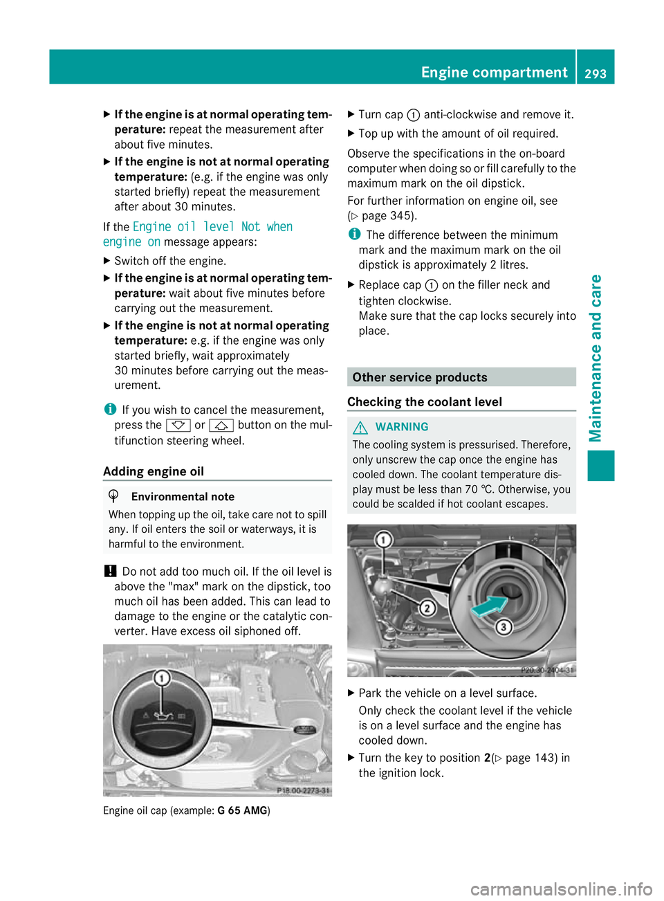
verter. Have excess oil siphoned off. Engine oil cap (example:
G 65 AMG) X
Turn cap :anti-clockwise and remove it.
X Top up with the amount of oil required.
Observe the specifications in the on-board
computer when doing so or fill carefully to the
maximum mark on the oil dipstick.
For further information on engine oil, see
(Y page 345).
i The difference between the minimum
mark and the maximum mark on the oil
dipstick is approximately 2litres.
X Replace cap :on the filler neck and
tighten clockwise.
Make sure that the cap locks securely into
place. Other service products
Checking the coolant level G
WARNING
The cooling system is pressurised. Therefore,
only unscrew the cap once the engine has
cooled down. The coolan ttemperature dis-
play must be less than 70 †. Otherwise, you
could be scalded if hot coolant escapes. X
Park the vehicle on a level surface.
Only chec kthe coolant level if the vehicle
is on a level surface and the engine has
cooled down.
X Turn the key to position 2(Ypage 143) in
the ignition lock. Engine compartment
293Maintenance and care Z
Page 297 of 357
X
Chec kthe coolant temperature display in
the instrument cluster.
The coolant temperature must be below
70 †.
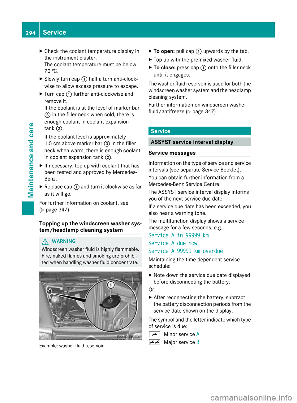
X Slowly turn cap :half a turn anti-clock-
wise to allow excess pressure to escape.
X Turn cap :further anti-clockwise and
remove it.
If the coolant is at the level of marker bar
= in the filler neck when cold, there is
enough coolant in coolant expansion
tank ;.
If the coolant level is approximately
1.5 cm above marker bar =in the filler
neck when warm, there is enough coolant
in coolant expansion tank ;.
X If necessary, top up with coolant that has
been tested and approved by Mercedes-
Benz.
X Replace cap :and turn it clockwise as far
as it will go.
For further information on coolant, see
(Y page 347).
Topping up the windscreen washer sys-
tem/headlampc leaning systemG
WARNING
Windscreen washer fluid is highly flammable.
Fire, naked flames and smoking are prohibi-
ted when handling washer fluid concentrate. Example: washer fluid reservoir X
To open: pull cap:upwards by the tab.
X Top up with the premixed washer fluid.
X To close: press cap :onto the filler neck
until it engages.
The washer fluid reservoir is used for both the
windscreen washer syste mand the headlamp
cleaning system.
Further informatio nonwindscreen washer
fluid/antifreeze (Y page 347). Service
ASSYST service interval display
Service messages Information on the type of service and service
intervals (see separate Service Booklet).
You can obtain further information from a
Mercedes-Benz Service Centre.
The ASSYST service interval display informs
you of the nex tservice due date.
If a service due date has been exceeded, you
also hear a warning tone.
The multifunction display shows a service
message for a few seconds, e.g.:
Service A in 99999 km Service A due now
Service A 99999 km overdue
Maintaining the time-dependen
tservice
schedule:
X Note down the service due date displayed
before disconnecting the battery.
Or:
X After reconnecting the battery, subtract
the battery disconnection periods from the
service date shown on the display.
The symbol and the letter indicate which type
of service is due:
¯ Minor service A ±
Major service B294
ServiceMaintenance and care
Page 307 of 357
Useful information
i This Owner's Manual describes all mod-
els, series and optional equipment for your
vehicle that were available at the time of
going to press. Country-specific differen-
ces are possible. Note that your vehicle
may not be fitted with all features descri-
bed. This is also the case for systems and
functions relevant to safety.
i Read the information on qualified special-
ist workshops: (Y page 22). Where will I find...?
Warning triangle
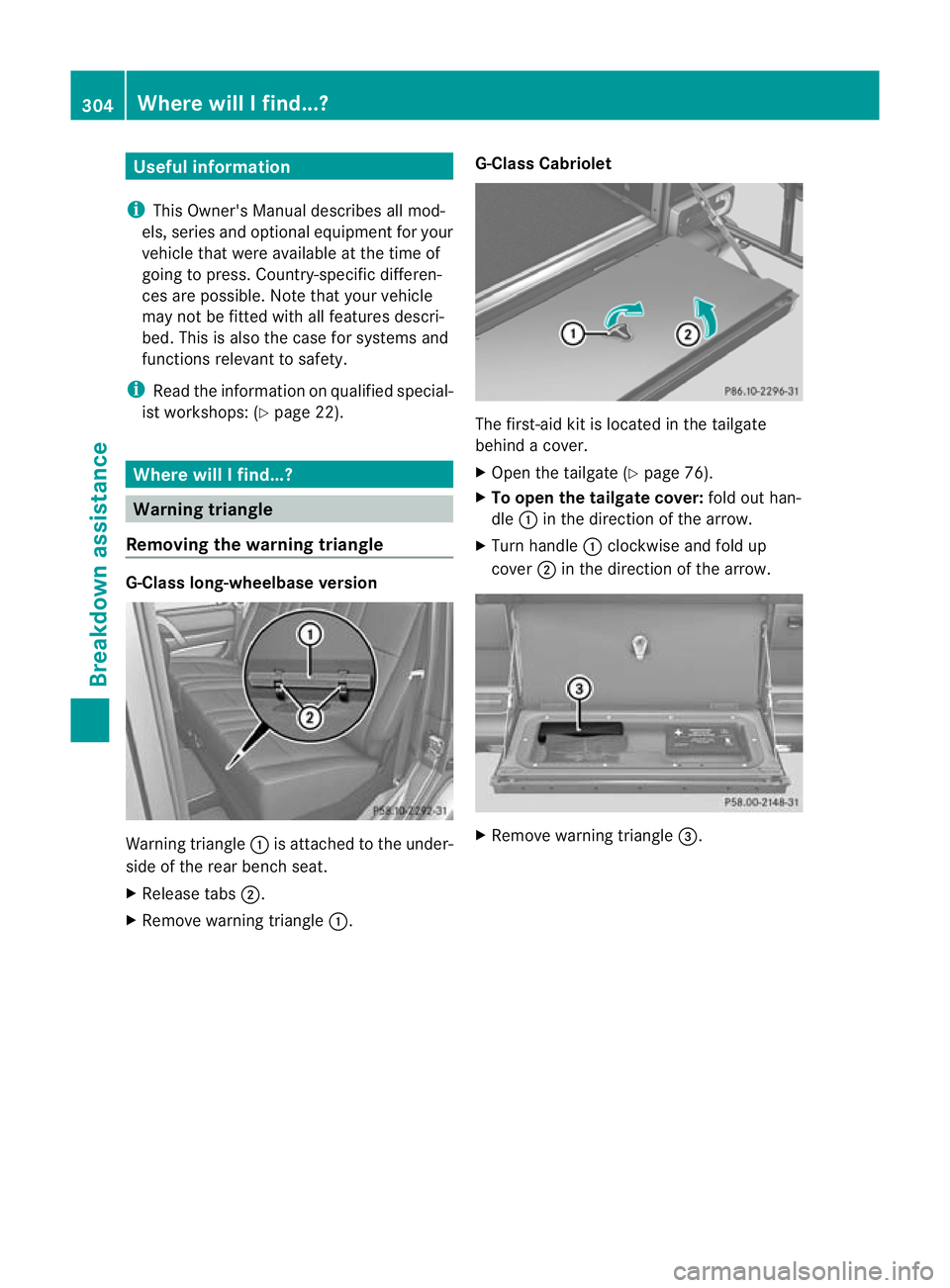
Removing the warning triangle G-Class long-wheelbase version
Warning triangle
:is attached to the under-
side of the rear bench seat.
X Release tabs ;.
X Remove warning triangle :.G-Class Cabriolet The first-aid kit is located in the tailgate
behind a cover.
X
Open the tailgate (Y page 76).
X To open the tailgate cover: fold out han-
dle :in the direction of the arrow.
X Turn handle :clockwise and fold up
cover ;in the direction of the arrow. X
Remove warning triangle =.304
Where will I find...?Breakdown assistance
Page 314 of 357

In order for the battery to achieve the maxi-
mum possible service life, it must always be
sufficiently charged.
Comply with safety precautions and take pro-
tective measures when handling batteries. WARNING
Avoid the creation of sparks and
heat.
Avoid fire, naked flames and smok-
ing. Creation of sparks.
Battery acid is caustic.
Avoid contact with the skin, eyes
or clothing.
Wear eye protection.
Keep childre
naway. Observe this Owner's Manual.
The vehicle battery, like other batteries, can
discharge over time if you do not use the
vehicle. In such cases, have the battery dis-
connected at a qualified specialist workshop.
You can also charge the battery with a
charger recommended by Mercedes-Benz.
For more information, please contac taquali-
fied specialist workshop.
Explosive gases are created during charging
and jump-starting.
For safety reasons, Mercedes-Benz recom-
mends that you only use batteries which have
been tested and approved for your vehicle by
Mercedes-Benz .These batteries provide
increased impact protection to prevent vehi-
cle occupants from suffering acid burns
should the battery be damaged in the event
of an accident.
Have the battery charge checked more fre-
quently if you use the vehicle mainly for short trips or if you leave it standing idle for a
lengthy period. Consult a qualified specialist
workshop if you wish to leave your vehicle
parked up for a long period of time.
i
When you park the vehicle, remove the
key if you do not require any electrical con-
sumers. The vehicle will then use very little
energy, thus conserving battery power.
i If the power supply has been interrupted,
e.g. due to a discharged battery, you will
have to:
R set the clock. Information on setting the
clock can be found in the separate oper-
ating instructions.
On vehicles with COMAND Online and a
navigation system, the clock is set auto-
matically.
R reset the head restraints on the front
seats (Y page 93).
R reset the function for folding the exterior
mirrors in/out automatically, by folding
the mirrors out once (Y page 100). Charging the battery
G
WARNING
During charging and jump-starting, explosive
gases can escape from the battery. There is a
risk of an explosion.
Particularly avoid fire, naked flames, creating
sparks and smoking. Ensure there is sufficient
ventilation while charging and jump-starting.
Do not lean over a battery. G
WARNING
Battery acid is caustic. There is a risk of injury.
Avoid contact with the skin, eyes or clothing.
Do not inhale any battery gases. Do not lean
over the battery. Keep children away from
batteries. Wash battery acid immediately with
water and seek medical attention. Battery (vehicle)
311Breakdown assistance Z
Page 334 of 357
is being changed. It is not suited for per-
forming maintenance work under the vehi-
cle.
R avoid changing the wheel on uphill and
downhill slopes.
R before raising the vehicle, secure it from
rolling away by applying the parking brake
and inserting wheel chocks. Neve rdisen-
gage the parking brake while the vehicle is
raised.
R the jack must be placed on a firm, flat and
non-slip surface. On a loose surface, a
large, load-bearing underlay must be used.
On a slippery surface, a non-slip underlay
must be used, e.g. rubber mats.
R do not use wooden blocks or similar
objects as a jac kunderlay. Otherwise, the
jack will not be able to achieve its load-
bearing capacity due to the restricted
height.
R make sure tha tthe distance between the
underside of the tyres and the ground does
not exceed 3 cm.
R never place your hands or feet under the
raised vehicle.
R never lie under the raised vehicle.
R never start the engine when the vehicle is
raised.
R never open or close a door or the tailgate
when the vehicle is raised.
R make sure that no persons are present in
the vehicle when the vehicle is raised. X
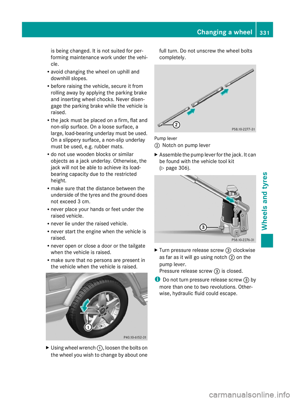
Using wheel wrench :, loosen the bolts on
the wheel you wish to change by about one full turn. Do not unscrew the wheel bolts
completely.
Pump lever
;
Notch on pump lever
X Assemble the pump lever for the jack. It can
be found with the vehicle tool kit
(Y page 306). X
Turn pressure release screw =clockwise
as far as it will go using notch ;on the
pump lever.
Pressure release screw =is closed.
i Do not turn pressure release screw =by
more than one to two revolutions. Other-
wise, hydraulic fluid could escape. Changing
awheel
331Wheels and tyres Z