2012 MERCEDES-BENZ G-CLASS SUV lock
[x] Cancel search: lockPage 206 of 357
X
Press LOW RANGE button ;.
When the shift procedure is complete, the
LOW RANGE transfer case position appears
in the multifunction display.
Indicator lamp :lights up.
X Shift the transmission to position D.
Switching off the off-road gear ratio G
WARNING
When the transfer case is in the neutral posi-
tion, power transmission to the driven wheels
is interrupted. As a result, the vehicle could
roll away .There is a risk of an accident.
Secure the vehicle with the parking brake, and
on uphill or downhill gradients, also secure it
with a device such as a wheel chock.
! Only carry out the gear selection if:
R the engine is running.
R the vehicle is rolling.
R the automatic transmission is in selector
lever position N.
R you are driving at less than 70 km/h.
You could otherwise damage the transfer
case.
X Press button ;.
When the shift procedure is complete, the
HIGH RANGE transfer case position appears
in the multifunction display.
Indicator lamp :goes out.
If the gear change is not completed, the fol-
lowing messages could appearint he display:
R TC shift conditions not fulfilled You have not met one or more shift condi-
tions.
R TC NEUTRAL on The transfer case has cancelled the gear
change process and is in N.TheN transfer
case position appears in the multifunction
display.
R TC shift cancelled The transfer case has not performed the
gear change process. X
Repeatt he gear change process.
Make sure to meet all conditions for chang-
ing gears.
R TC Malfunction Visit workshop There is a malfunction in the transfer case.
X Do not shift the transfer case.
X Have the vehicle checked as soon as pos-
sible at a qualified specialist workshop.
Shifting to neutral G
WARNING
When the transfer case is in the neutral posi-
tion, power transmission to the driven wheels
is interrupted. As a result, the vehicle could
roll away.T here is a risk of an accident.
Secure the vehicle with the parking brake, and
on uphill or downhill gradients, also secure it
with a device such as a wheel chock.
X Turn the key to position 2(Ypage 143) in
the ignition lock.
X Apply the parking brake.
X Depress the brake pedal.
X Move the selector lever to position
N(Y page 149).
X Press and hold LOW RANGE button ;for
approximately 10 seconds.
Once the gear change procedure is com-
plete, TC in neutral message appears in
the multifunction display for approximately
5s econds.
If the gear change is not completed, the fol-
lowing messages could appear in the display
(Y page 241).
i If the transfer case is in Neutral, the key
is in the ignition lock and you open the driv-
er's door, the TC in neutral message
appears in the multifunction display. If you
then release the parking brake, a warning
tone will sound. Off-road driving systems
203Driving and parking Z
Page 207 of 357
Differential lock
General notes G
WARNING
Whe ndifferential locks are engaged on a firm,
high-grip surface, the vehicle's steerability is
greatly impaired .Inparticular, engaging the
differential locks when cornering could lead
to you losing control of the vehicle .There is a
risk of an accident.
Disengage the differential locks immediately
on firm, high-grip surfaces.
! To prevent damage in the transfer case,
you may only operate the vehicle on a roller
dynamometer (single-axle roller dynamom-
eter) if:
R the axle that is not being driven is raised.
or
R the corresponding propeller shaft is dis-
connected and the transfer case differ-
ential lock is activated.
Otherwise, the transfer case can be dam-
aged.
Differential locks improve the traction of the
vehicle.
Your vehicle is equipped with adifferential
lock for:
R the transfer case: this controls the balance
between the front and rear axles.
R the rear axle: this controls the balance
between the wheels on the rear axle.
R the front axle: this controls the balance
between the wheels on the front axle.
Activating the differentia llock Important safety notes
G
WARNING
When differential locks are engaged on a firm,
high-grip surface, the vehicle's steerability is
greatly impaired. In particular, engaging the
differential locks when cornering could lead to you losing control of the vehicle
.There is a
risk of an accident.
Disengage the differential locks immediately
on firm, high-grip surfaces. G
WARNING
ABS, 4ETS, ESP ®
and BAS are deactivated
while the differential locks are engaged. As a
result, the wheels could lock when braking
and the braking distance is increased. There
is a risk of an accident.
Disengage the differential locks immediately
on firm, high-grip surfaces.
! Only activate the differential locks when:
R you are driving at walking pace.
R the driven wheels are not spinning.
R you are not driving on a firm road surface.
General notes
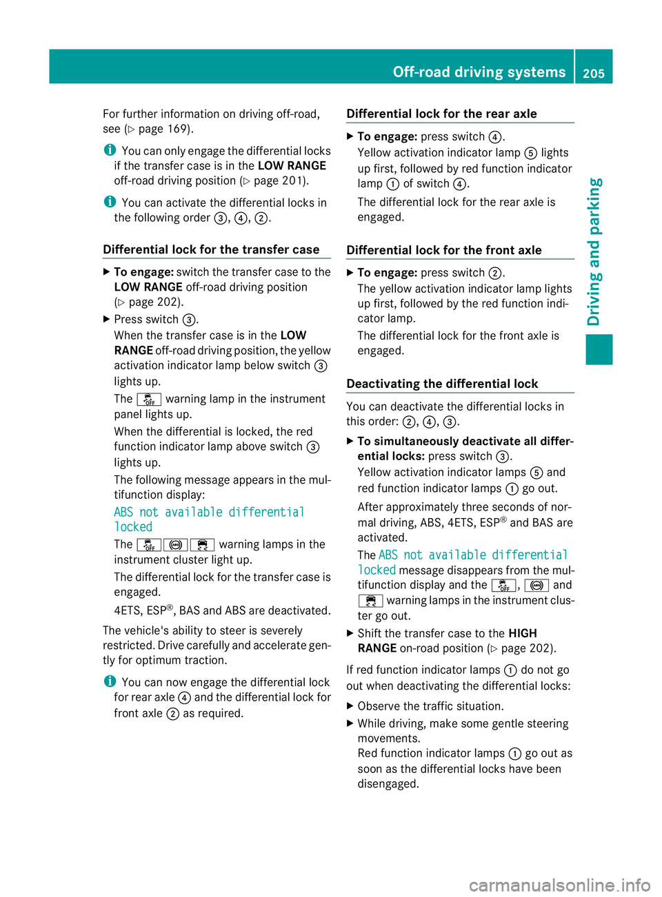
The switches are located on the centre con-
sole. :
Function indicator lamps (red)
; Differential lock for the front axle
= Differential lock for the transfer case
? Differential lock for the rear axle
A Activation indicator lamps (yellow)
Activate the differential locks:
R off-road
R to deactivate ABS, 4ETS, ESP ®
and BAS
when off-road
R when fording 204
Off-road driving systemsDriving and parking
Page 208 of 357
For further information on driving off-road,
see (Y page 169).
i You can only engage the differential locks
if the transfer case is in the LOW RANGE
off-road driving positio n(Ypage 201).
i You can activate the differential locks in
the following order =,?,;.
Differential lock for the transfer case X
To engage: switch the transfer case to the
LOW RANGE off-road driving position
(Y page 202).
X Press switch =.
When the transfer case is in the LOW
RANGE off-road driving position, the yellow
activation indicator lamp below switch =
lights up.
The å warning lamp in the instrument
panel lights up.
When the differential is locked, the red
function indicator lamp above switch =
lights up.
The following message appears in the mul-
tifunction display:
ABS not available differential locked
The
å!÷ warning lamps in the
instrument cluster light up.
The differential lock for the transfer case is
engaged.
4ETS, ESP ®
, BASa nd ABS ar edeactivated.
The vehicle's ability to steer is severely
restricted. Drive carefully and accelerate gen-
tly for optimum traction.
i You can now engage the differential lock
for rear axle ?and the differential lock for
front axle ;as required. Differential lock for the rear axle X
To engage: press switch ?.
Yellow activation indicator lamp Alights
up first, followed by red function indicator
lamp :of switch ?.
The differential lock for the rear axle is
engaged.
Differential lock for the front axle X
To engage: press switch ;.
The yellow activation indicator lamp lights
up first, followed by the red function indi-
cator lamp.
The differential lock for the front axle is
engaged.
Deactivating the differential lock You can deactivate the differential locks in
this order:
;,?,=.
X To simultaneously deactivate all differ-
ential locks: press switch=.
Yellow activation indicator lamps Aand
red function indicator lamps :go out.
After approximately three seconds of nor-
mal driving, ABS, 4ETS, ESP ®
and BAS are
activated.
The ABS not available differential
locked message disappears from the mul-
tifunction display and the å,!and
÷ warning lamps in the instrument clus-
ter go out.
X Shift the transfer case to the HIGH
RANGE on-road position (Y page 202).
If red function indicator lamps :do not go
out when deactivating the differential locks:
X Observe the traffic situation.
X While driving, make some gentle steering
movements.
Red function indicator lamps :go out as
soon as the differential locks have been
disengaged. Off-road driving systems
205Driving and parking Z
Page 211 of 357
Trailer power supply
! You can connect accessories with a max-
imum power consumption of 180 W to the
permanent powe rsupply.
You must no tcharge a trailer battery using
the power supply.
The trailer socket of your vehicle is equipped
at the factory with apermanen tpower supply.
The permanent power supply is supplied via
trailer socket pin 9.
You can find more information about fitting
the trailer electrics at a qualified specialist
workshop. Trailer with 7-pin connector
General notes You can make a connection to the 13-pin
socket on the ball coupling using an adapter
or, if necessary, an adapter cable. Both can
be obtained at a qualified specialist work-
shop.
Fitting the adapter !
Make sure that there is sufficient cable
play so that the cable cannot become
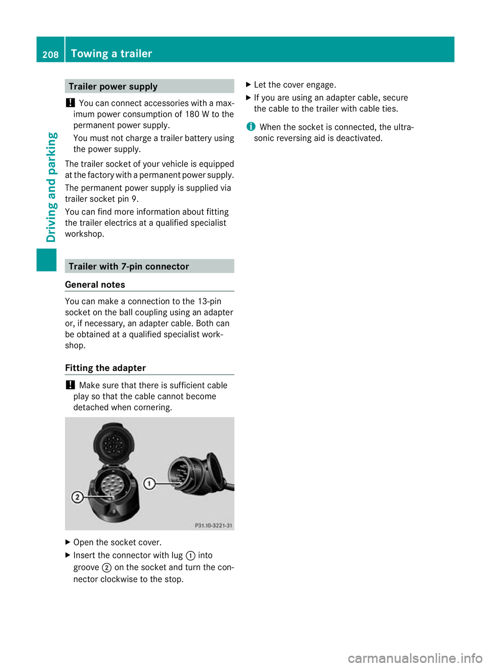
detached when cornering. X
Open the socket cover.
X Insert the connector with lug :into
groove ;on the socket and turn the con-
nector clockwise to the stop. X
Let the cover engage.
X If you are using an adapter cable, secure
the cable to the trailer with cable ties.
i When the socket is connected, the ultra-
sonic reversing aid is deactivated. 208
Towing
atrailerDriving an d parking
Page 215 of 357

=
Rev counter (Y page 212)
? Coolan ttemperature (Y page 212)
A Fuel gauge
B Instrument cluster lighting (Y page 212)Instrument cluster lighting
The lighting in the instrument cluster, in the
displays and the controls in the vehicle inte-
rior can be adjusted using the brightness con-
trol knob.
The brightness control knob is located on the
bottom left of the instrument cluster
(Y page 211).
X Turn the brightness control knob clockwise
or anti-clockwise.
If the light switch is set to Ã,Tor
L, the brightness is dependen tupon
the brightness of the ambient light.
i The light senso rinthe instrumentc luster
automatically controls the brightness of
the multifunction display.
In daylight, the displays in the instrument
cluster are not illuminated. Displaying the coolant temperature
The coolan ttemperature gauge is in the
instrument cluster on the right-hand side
(Y page 211).
The reading may rise up to 120 †undernor-
mal driving conditions if the coolant has been
filled correctly.
At high outside temperatures and when driv-
ing uphill, the coolant temperature may rise
to the end of the scale. Rev counter
! Do not drive in the overrevving range.
Doing so will damage the engine.
The red band in the rev counter indicates the
engine's overrevving range. The fuel supply is interrupted to protec
tthe
engine when the red band is reached. Outside temperature display
G
WARNING
At temperatures just above freezing point, the
street may be icy, especially in wooded areas
or on bridges. If you do not adapt your driving
style to the conditions, the vehicle could skid.
For this reason, adapt your driving style and
speed to the weather conditions.
The outside temperature displayi s in the mul-
tifunction display (Y page 214).
Changes in the outside temperature are dis-
played after a short delay. Speedometer with segments
The segments in the speedometer indicate
which speed range is available.
R Cruise control activated (Y page 173):
The segments light up from the stored
speed to the maximum speed.
R Variable SPEEDTRONIC activated
(Y page 178):
The segments light up from the start of the
scale to the selected limit speed.
R DISTRONIC PLUS activated (Y page 184):
One or two segments in the set speed
range light up.
R DISTRONIC PLUS detects avehicle in front:
The segments between the speed of the
vehicle in fron tand the stored speed light
up. 212
Displays and operationOn-board computer and displays
Page 216 of 357
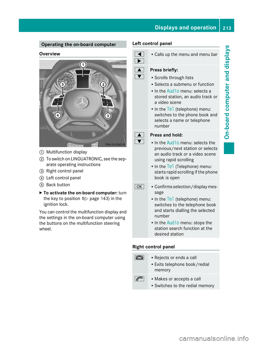
Operating the on-board computer
Overview :
Multifunction display
; To switch on LINGUATRONIC, see the sep-
arate operating instructions
= Right control panel
? Left control panel
A Back button
X To activate the on-board computer: turn
the key to position 1(Ypage 143) in the
ignition lock.
You can control the multifunction display and
the settings in the on-board computer using
the buttons on the multifunction steering
wheel. Left control panel =
; R
Calls up the menu and menu bar 9
:
Press briefly:
R
Scrolls through lists
R Selects a submenu or function
R In the Audio menu: selects a
stored station, an audio trac kor
a video scene
R In the Tel (telephone) menu:
switches to the phone book and
selects a name or telephone
number 9
:
Press and hold:
R
In the Audio menu: selects the
previous/next statio norselects
an audio trac koravideo scene
using rapid scrolling
R In the Tel (Telephone) menu:
starts rapid scrolling if the phone
book is open a R
Confirms selection/display mes-
sage
R In the Tel (telephone) menu:
switches to the telephone book
and starts dialling the selected
number
R In the Audio menu: stops the
station search function at the
desired station Right control panel
~ R
Rejects or ends a call
R Exits telephone book/redial
memory 6 R
Makes or accepts a call
R Switches to the redial memory Displays and operation
213On-board computer and displays Z
Page 225 of 357
Lights
Setting the daytime driving lights
The Day lights function can only be
switched on with the engine turned off.
X Press the =or; button on the steer-
ing wheel to selec tthe Settings menu.
X Press the :or9 button to select the
Light submenu.
X Press ato confirm.
X Press :or9 to select the Daytime driving lights: function.
If the Daytime driving lights have
been switched on, the cone of light and the
W symbol in the multifunction display
are shown in red.
X Press the abutton to save the setting.
Further information on daytime driving lights
(Y page 105).
Surround lighting and exterior lighting
delayed switch-off
X Press the =or; button on the steer-
ing wheel to select the Settings menu.
X Press the :or9 button to select the
Light submenu.
X Press ato confirm.
X Press :or9 to select the Sur‐ round lighting function.
When the Surround lighting function is
activated, the cone of light in the multi-
function display is shown in red.
X Press the abutton to save the setting.
Deactivating delayed switch-off of the exte-
rior lighting temporarily:
X Before leaving the vehicle, turn the key to
position 0(Ypage 143) in the ignition lock.
X Turn the key to position 2in the ignition
lock (Y page 143).
The exterior lighting delayed switch-off is
deactivated.
Delayed switch-off of the exterior lighting is
reactivated the next time you start the
engine. If you have activated the
Surround light‐ ing function and the light switch is set to
Ã, the following functions are activated
when it is dark:
R Surround lighting: the exterior lighting
remains lit for 40 seconds after unlocking
with the key. If you start the engine, the
surround lighting is switched off and auto-
matic headlamp mode is activated
(Y page 105).
R Exterior lighting delayed switch-off: the
exterior lighting remains lit for
60 seconds after the engine is switched off.
If you close all the doors and the boot lid,
the exterior lighting goes off after
15 seconds.
i Depending on your vehicle's equipment,
when the surround lighting and delayed
switch-off exterior lighting are on, the fol-
lowing light up:
R side lamps
R foglamps
R dipped-beamh eadlamps
R daytime driving lights
R surround lighting in the exterior mirrors
Activating/deactivating the interior light-
ing delayed switch-off
If you activate the Light. delay function,
the interior lighting remains on for
20 seconds after you remove the key from the
ignition lock.
X Press the =or; button on the steer-
ing wheel to select the Settings menu.
X Press the :or9 button to select the
Light submenu.
X Press ato confirm.
X Press :or9 to select the Light. delay function.
When the Light. delay function is acti-
vated, the vehicle interior is displayed in
red in the multifunction display.
X Press the abutton to save the setting. 222
Menus and submenusOn-board computer and displays
Page 226 of 357
Vehicle
Setting permanen
tSPEEDTRONIC
X Press the =or; button on the steer-
ing wheel to select the Settings menu.
X Press the :or9 button to select the
Vehicle submenu.
X Press ato confirm.
X Press :or9 to select the Limit speed (winter tyres): function.
You will see the current setting.
X Press ato confirm.
X Press the :or9 button to adjust
permanent SPEEDTRONIC in increments of
ten (230 km/h to
160 km/h ). The
Off set-
ting switches permanent SPEEDTRONIC
off.
X Press the abutton to store the entry.
For further information on permanent SPEED-
TRONIC (Y page 182).
Switching the automatic locking feature
on/off
If you activate the Auto. door locks func-
tion, the vehicle is centrally locked above a
speed of approximately 15 km/h.
X Press the =or; button on the steer-
ing wheel to select the Settings menu.
X Press the :or9 button to select the
Vehicle submenu.
X Press ato confirm.
X Press :or9 to select the Auto. door locks function.
When the Auto. door locks function is
activated, the vehicle doors are displayed
in red in the multifunction display.
X Press the abutton to save the setting.
For further information on the automatic lock-
ing feature, see (Y page 74). Activating/deactivating the acoustic
locking confirmation
If you switch on the
Acoustic Lock function,
an acoustic signal sounds when you lock the
vehicle.
X Press the =or; button on the steer-
ing wheel to select the Settings menu.
X Press the :or9 button to select the
Vehicle submenu.
X Press ato confirm.
X Press the :or9 button to select the
Acoustic Lock function.
If the Acoustic Lock function is activated,
the & symbol in the multifunction dis-
play lights up red.
X Press the abutton to save the setting.
Heating Auxiliary heating departure time
G
WARNING
Exhaust fumes are produced when the auxili-
ary heating is in operation. Inhaling these
exhaust fumes can be poisonous. You should
therefore switch off the auxiliary heating in
confined spaces without an extraction sys-
tem, e.g. a garage. G
WARNING
When operating the auxiliary heating parts of
the vehicle can get very hot. Make sure that
the exhaust system does not under any cir-
cumstances come into contact with easily
ignitable material such as dry grass or fuels.
The material could otherwise ignite and set
the vehicle alight. Choose your parking spot
accordingly.
Operating the auxiliary heating is thus pro-
hibited at filling stations or when your vehicle
is being refuelled. You must therefore switch
off the auxiliary heating at filling stations.
! Operating the auxiliary heating/ventila-
tion draws on the vehicle battery. After you
have heated or ventilated the vehicle a Menus and submenus
223On-board computer and displays Z