2012 MERCEDES-BENZ E-CLASS ESTATE clock
[x] Cancel search: clockPage 244 of 457

The trailer's permanen
tpower supply is
switched off in the event of low vehicle supply
voltage and after six hours at the latest.
You can find more information about instal-
ling the trailer electric sataqualified special-
ist workshop. Bulb failure indicator for LED lamps
i If LED lamps are fitted in the trailer, an
error message may appear in the multi-
function display even if there is no fault. The
reason for the error message could be that
the curren thas falle nbelow the minimum
of 50 mA.
To ensure reliable operation of the bulb failure
indicator, each LED chain in the trailer lighting
must be guaranteed a minimum current of
50 mA. Trailer with 7-pin connector
General notes Trailers with 7-pin connector:
you can
make a connection to the 13-pin connector
on the ball coupling using an adapter plug or,
if necessary, an adapter cable. Both can be
obtained in a qualified specialist workshop.
Fitting the adapter !
Make sure that there is sufficien tcable
play so that the cable canno tbecome
detached when cornering. X
Open the socket cover.
X Insert connector with lug :into
groove ;of the socket. Turn the connec-
tor clockwise to the stop.
X Let the cover engage.
X If you are using an adapter cable, secure
the cable to the trailer with cable ties. Towing
atrailer
241Driving an d parking Z
Page 249 of 457
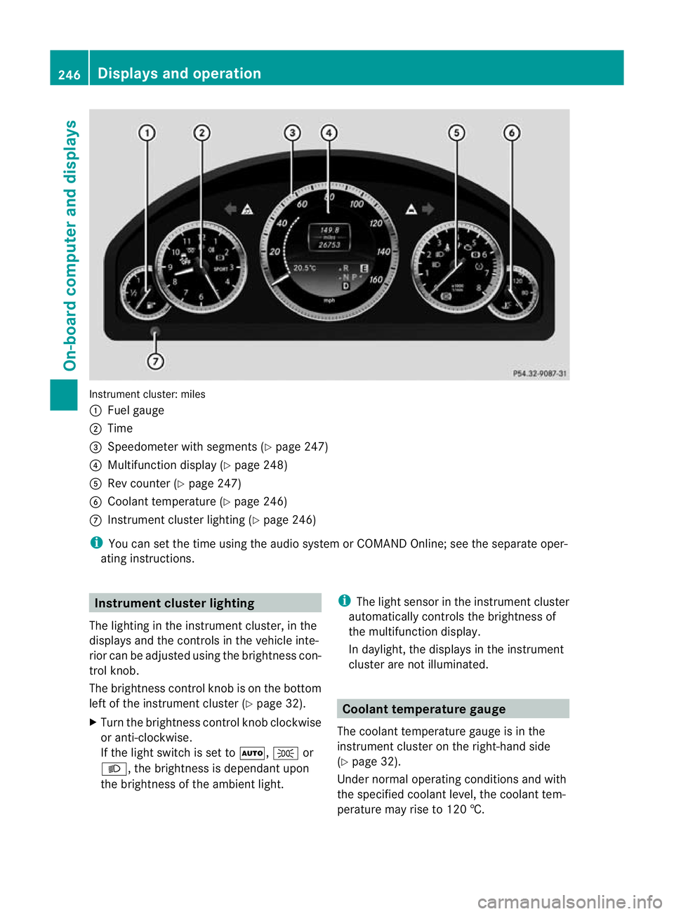
Instrument cluster: miles
:
Fuel gauge
; Time
= Speedometer with segments (Y page 247)
? Multifunction display (Y page 248)
A Rev counter (Y page 247)
B Coolant temperature (Y page 246)
C Instrument cluster lighting (Y page 246)
i You can set the time using the audio system or COMAND Online; see the separate oper-
ating instructions. Instrument clusterl
ighting
The lighting in the instrumen tcluster, in the
displays and the controls in the vehicle inte-
rior can be adjusted using the brightness con-
trol knob.
The brightness control knob is on the bottom
left of the instrument cluster (Y page 32).
X Turn the brightness control knob clockwise
or anti-clockwise.
If the light switch is set to Ã,Tor
L, the brightness is dependant upon
the brightness of the ambien tlight. i
The light sensor in the instrumen tcluster
automatically controls the brightness of
the multifunction display.
In daylight, the displays in the instrument
cluster are not illuminated. Coolant temperature gauge
The coolan ttemperature gauge is in the
instrument cluster on the right-hand side
(Y page 32).
Under normal operating conditions and with
the specified coolant level, the coolant tem-
perature may rise to 120 †. 246
Displays and operationOn-board computer and displays
Page 314 of 457
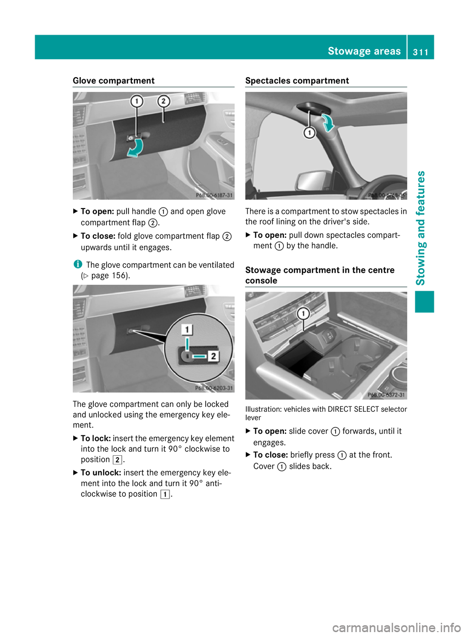
Glove compartment
X
To open: pull handle :and open glove
compartment flap ;.
X To close: fold glove compartment flap ;
upwards until it engages.
i The glove compartment can be ventilated
(Y page 156). The glove compartment can only be locked
and unlocked using the emergency key ele-
ment.
X To lock: insert the emergency key element
into the lock and turn it 90° clockwise to
position 2.
X To unlock: insert the emergency key ele-
ment into the lock and turn it 90° anti-
clockwise to position 1. Spectacles compartment There is a compartment to stow spectacles in
the roof lining on the driver's side.
X
To open: pull down spectacles compart-
ment :by the handle.
Stowage compartment in the centre
console Illustration: vehicles with DIRECT SELECT selector
lever
X
To open: slide cover :forwards, until it
engages.
X To close: briefly press :at the front.
Cover :slides back. Stowage areas
311Stowing and features Z
Page 326 of 457
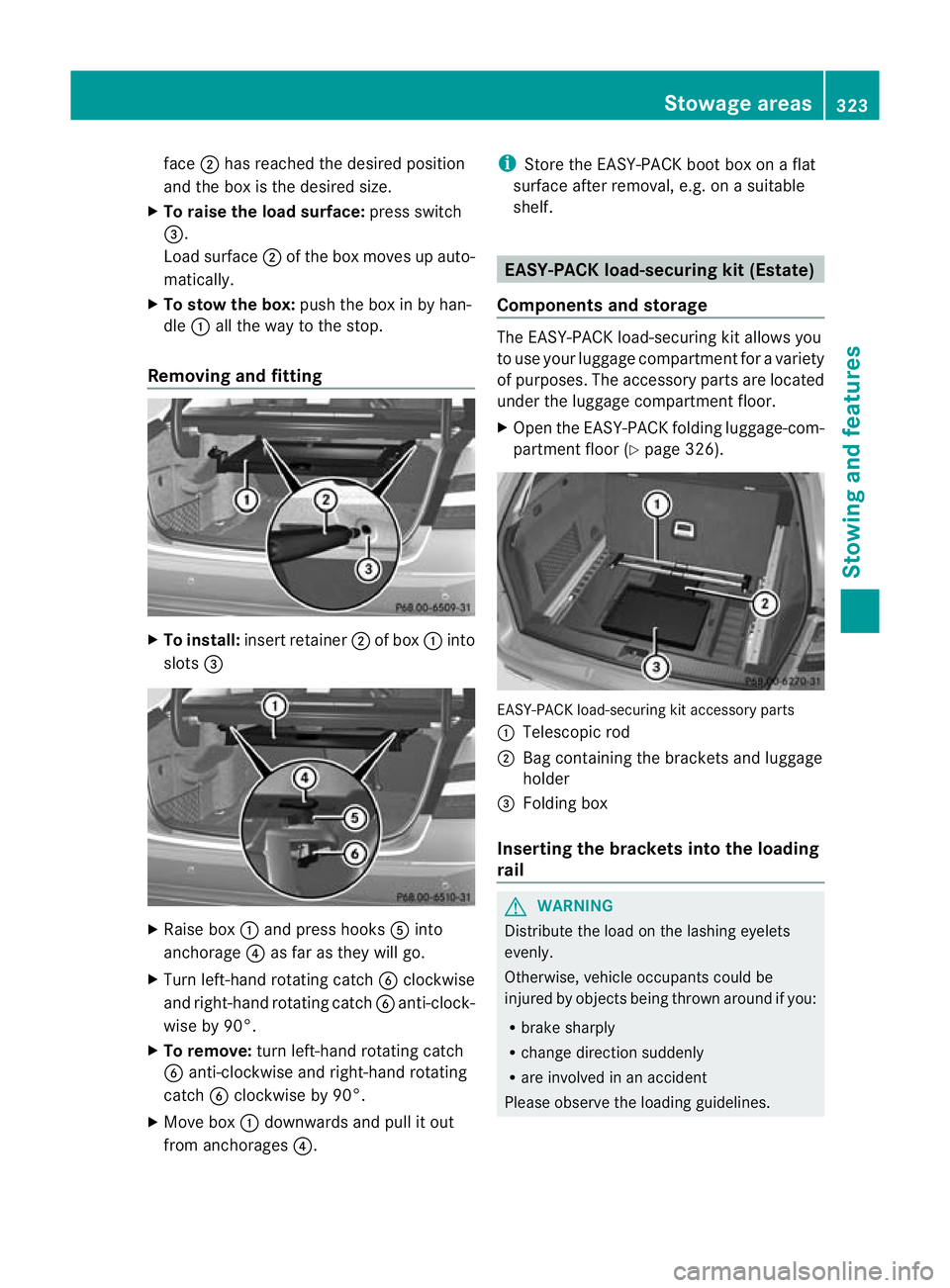
face
;has reached the desired position
and the box is the desired size.
X To raise the load surface: press switch
=.
Load surface ;of the box moves up auto-
matically.
X To stow the box: push the box in by han-
dle :all the way to the stop.
Removing and fitting X
To install: insert retainer ;of box :into
slots = X
Raise box :and press hooks Ainto
anchorage ?as far as they will go.
X Turn left-hand rotating catch Bclockwise
and right-hand rotating catch Banti-clock-
wise by 90°.
X To remove: turn left-hand rotating catch
B anti-clockwise and right-hand rotating
catch Bclockwise by 90°.
X Move box :downwards and pull it out
from anchorages ?. i
Store the EASY-PACK boot box on a flat
surface after removal, e.g. on a suitable
shelf. EASY-PACK load-securing kit (Estate)
Components and storage The EASY-PACK load-securing kit allows you
to use you
rluggage compartmen tfor a variety
of purposes. The accessory parts are located
under the luggage compartment floor.
X Open the EASY-PACK folding luggage-com-
partment floor (Y page 326). EASY-PACK load-securing kit accessory parts
:
Telescopic rod
; Bag containing the brackets and luggage
holder
= Folding box
Inserting the brackets into the loading
rail G
WARNING
Distribute the load on the lashing eyelets
evenly.
Otherwise, vehicle occupants could be
injured by objects being thrown around if you:
R brake sharply
R change direction suddenly
R are involved in an accident
Please observe the loading guidelines. Stowage areas
323Stowing and features Z
Page 351 of 457
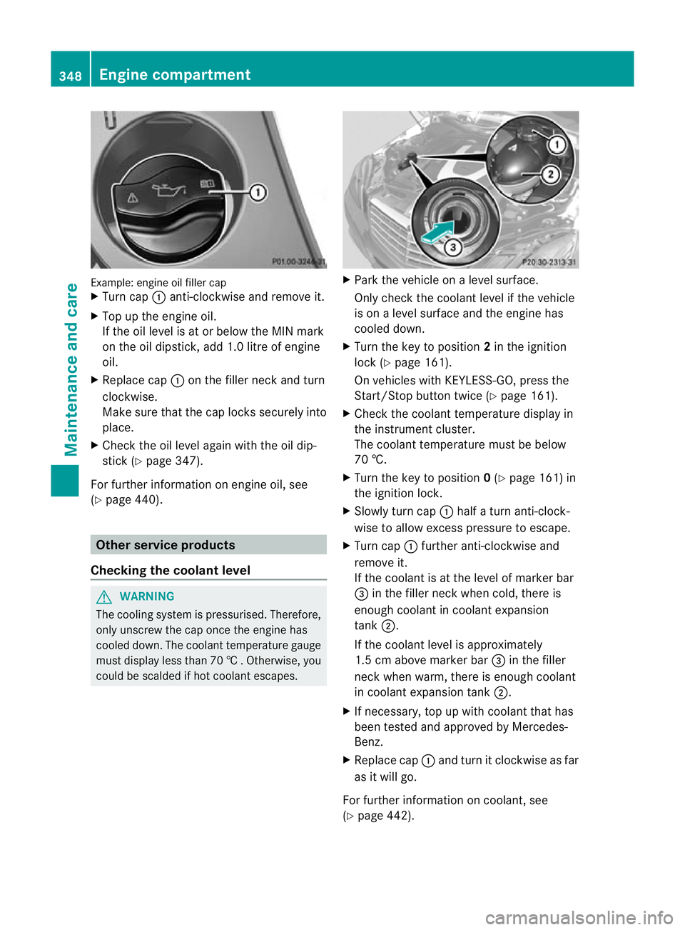
Example: engine oil fille
rcap
X Turn cap :anti-clockwise and remove it.
X Top up the engine oil.
If the oil level is at or below the MIN mark
on the oil dipstick, add 1. 0litre of engine
oil.
X Replace cap :on the filler neck and turn
clockwise.
Make sure that the cap locks securely into
place.
X Check the oil level again with the oil dip-
stick (Y page 347).
For further information on engine oil, see
(Y page 440). Other service products
Checking the coolant level G
WARNING
The cooling system is pressurised. Therefore,
only unscrew the cap once the engine has
cooled down. The coolan ttemperature gauge
must display less than 70 †.Otherwise, you
could be scalded if hot coolant escapes. X
Park the vehicle on a level surface.
Only check the coolant level if the vehicle
is on a level surface and the engine has
cooled down.
X Turn the key to position 2in the ignition
lock (Y page 161).
On vehicles with KEYLESS-GO, press the
Start/Stop button twice (Y page 161).
X Check the coolant temperature display in
the instrument cluster.
The coolant temperature must be below
70 †.
X Turn the key to position 0(Y page 161) in
the ignition lock.
X Slowly tur ncap : half a turn anti-clock-
wise to allow excess pressure to escape.
X Turn cap :further anti-clockwise and
remove it.
If the coolant is at the level of marker bar
= in the fille rneck when cold, there is
enough coolant in coolant expansion
tank ;.
If the coolant level is approximately
1.5 cm above marker bar =in the filler
neckw hen warm, there is enough coolant
in coolant expansion tank ;.
X If necessary, top up with coolant that has
been tested and approved by Mercedes-
Benz.
X Replace cap :and turn it clockwise as far
as it will go.
For further information on coolant, see
(Y page 442). 348
Engine compartmentMaintenance and care
Page 372 of 457
In order for the battery to achieve the maxi-
mum possible service life, it must always be
sufficiently charged.
The vehicle battery, like other batteries, can
discharge over time if you do not use the
vehicle .Insuch cases, have the battery dis-
connected at a qualified specialist workshop.
You can also charge the battery with a
charge rrecommended by Mercedes-Benz.
For more information, please contact a quali-
fied specialist workshop.
Have the battery charge checked more fre-
quently if you use the vehicle mainly for short
trips or if you leave it standing idle for a
lengthy period. Consult a qualified specialist
workshop if you wish to leave your vehicle
parked up for a long period of time.
i When you park the vehicle, remove the
key if you do not require any electrical con-
sumers. The vehicle will then use very little
energy, thus conserving battery power.
i After an interruption of the power supply,
e.g. the battery was discharged, you have
to:
R set the clock. Information on setting the
clock can be found in the separate oper-
ating instructions.
On vehicles with COMAND Online and a
navigation system, the clock is set auto-
matically.
R reset the function for folding the exterior
mirrors in/out automatically, by folding
the mirrors out once (Y page 120).Charging the battery
G
WARNING
Only charge the battery in a well-ventilated
area. As the battery is being charged, gases
can escape and generate minor explosions.
This could injure you and other persons or
cause damage to the paintwork or acid cor-
rosion on the vehicle. You can obtain information on battery charg-
ers which allow the batter
yto be charged
while still installed from a qualified specialist
workshop. G
WARNING
There is a risk of acid burns during the charg-
ing process due to the gases which escape
from the battery. Do not lean over the battery
during the charging process. G
WARNING
Battery acid is caustic. Avoid contact with the
skin, eyes or clothing.
! Only charge the installed battery with a
battery charger which has been tested and
approved by Mercedes-Benz. These battery
chargers allow the battery to be charged
while still installed in the vehicle.
! Only use battery chargers with a maxi-
mum charging voltage of 14.8 V.
! Only charge the battery using the jump-
start connection point.
The jump-starting connection point is in the
engine compartment (Y page 370).
Read the battery charger's operating instruc-
tions before charging the battery.
X Open the bonnet (Y page 345).
X Connect the battery charger to the positive
terminal and earth point in the same order
as when connecting the donor battery in
the jump-starting procedure
(Y page 370). Battery (vehicle)
369Breakdown assistance Z
Page 376 of 457
The battery must be connected and charged.
Otherwise, you:
R
cannot turn the key in the ignition lock to
position 2
R cannot shift the transmission to position
N on vehicles with automatic transmission
Vehicles with automatic transmission:
release the selector lever lock manually to
move it out of position P(Y page 179).
i Deactivate the automatic locking feature
(Y page 90). You could otherwise be locked
out when pushing or towing the vehicle.
Deactivate tow-away protection
(Y page 79) before the vehicle is towed. Fitting/removing the towing eye
Fitting the towing eye G
WARNING
The exhaust tail pipe may be hot. You could
burn yourself if you touch the tail pipe. Be
particularly careful when removing the rear
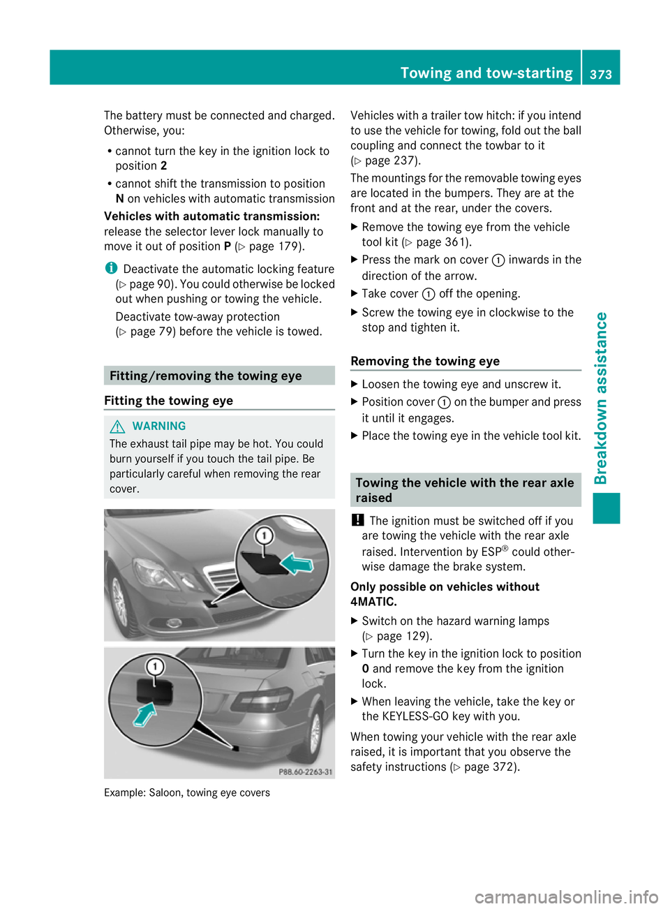
cover. Example: Saloon, towing eye covers Vehicles with a trailer tow hitch: if you intend
to use the vehicle for towing, fold out the ball
coupling and connect the towbar to it
(Y
page 237).
The mountings for the removable towing eyes
are located in the bumpers. They are at the
front and at the rear, under the covers.
X Remove the towing eye from the vehicle
tool kit (Y page 361).
X Press the mark on cover :inwards in the
direction of the arrow.
X Take cover :off the opening.
X Screw the towing eye in clockwise to the
stop and tighten it.
Removing the towing eye X
Loosen the towing eye and unscrew it.
X Position cover :on the bumper and press
it until it engages.
X Place the towing eye in the vehicle tool kit. Towing the vehicle with the rear axle
raised
! The ignition must be switched off if you
are towing the vehicle with the rear axle
raised. Intervention by ESP ®
could other-
wise damage the brake system.
Only possible on vehicles without
4MATIC.
X Switch on the hazard warning lamps
(Y page 129).
X Turn the key in the ignition lock to position
0and remove the key from the ignition
lock.
X When leaving the vehicle, take the key or
the KEYLESS-GO key with you.
When towing your vehicle with the rear axle
raised, it is importan tthat you observe the
safety instructions (Y page 372). Towing and tow-starting
373Breakdown assistance Z
Page 395 of 457
X
Turn crank Aclockwise until jack ?sits
completely on jacking point =and the
base of the jack lies evenly on the ground.
X Turn crank Auntil the tyre is raised a max-
imum of 3 cm off the ground.
Removing awheel !
AMG vehicles: during removal and repo-
sitioning of the wheel, the wheel rim can
strike the ceramic-brake dis cand damage
it. Therefore, take precautions and ge ta
second person to assist you. Alternatively,
you can use a second centring pin.
! Do not place wheel bolts in sand or dirt.
The threads of the wheel bolts and wheel
hubs could otherwise be damaged when
the bolts are tightened. X
Unscrew the uppermost wheel bolt com-
pletely.
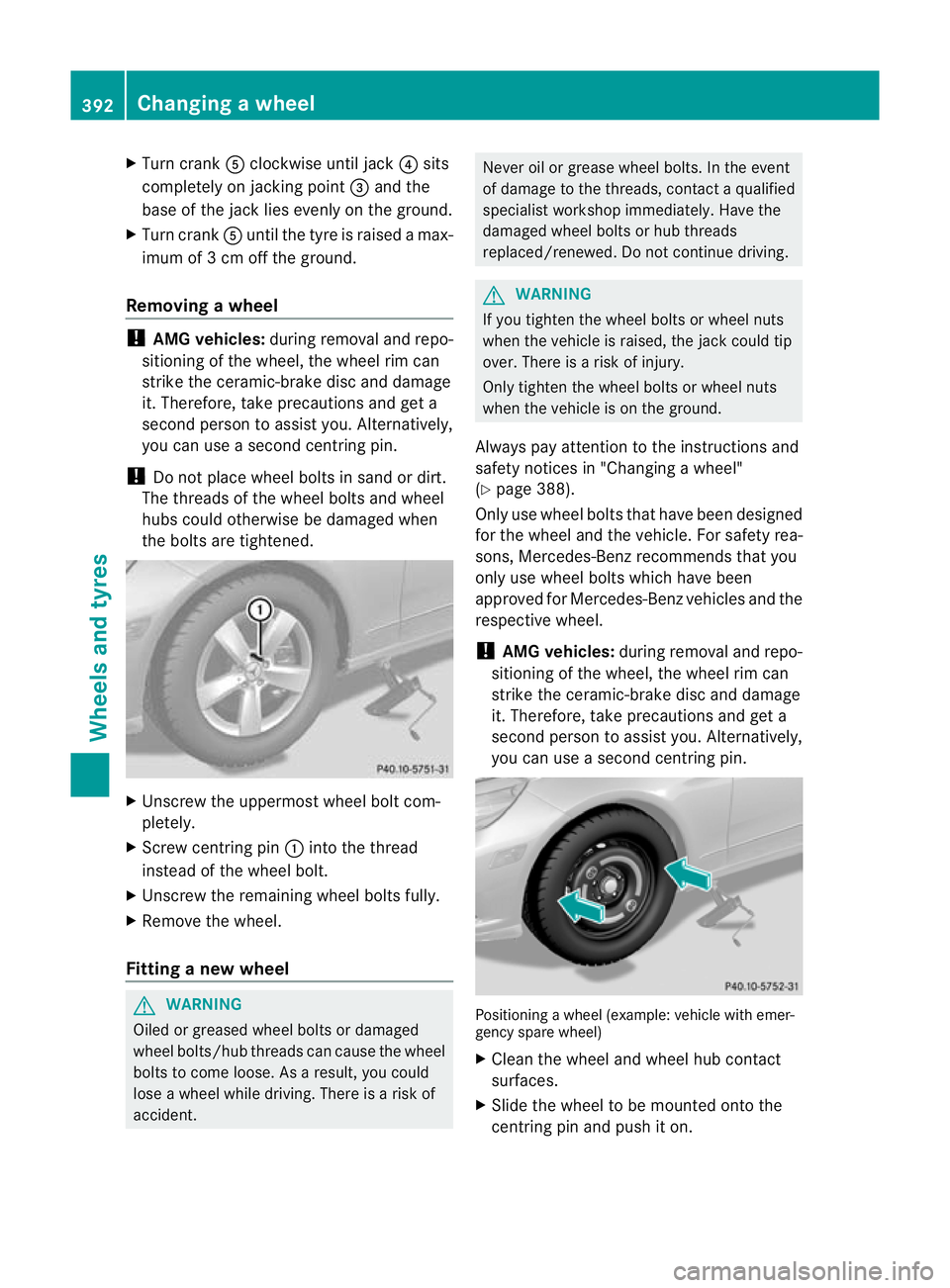
X Screw centring pin :into the thread
instead of the wheel bolt.
X Unscrew the remaining wheel bolts fully.
X Remove the wheel.
Fitting anew wheel G
WARNING
Oiled or greased wheel bolts or damaged
wheel bolts/hub threads can cause the wheel
bolts to come loose .As a result, you could
lose a wheel while driving. There is a risk of
accident. Never oil or grease wheel bolts. In the event
of damage to the threads, contact a qualified
specialist workshop immediately.H ave the
damaged wheel bolts or hub threads
replaced/renewed. Do no tcontinue driving. G
WARNING
If you tighten the wheel bolts or wheel nuts
when the vehicle is raised, the jack could tip
over. There is a risk of injury.
Only tighten the wheel bolts or wheel nuts
when the vehicle is on the ground.
Always pay attention to the instructions and
safety notices in "Changing a wheel"
(Y page 388).
Only use wheel bolts that have been designed
for the wheel and the vehicle. For safety rea-
sons, Mercedes-Benz recommends that you
only use wheel bolts which have been
approved for Mercedes-Benz vehicles and the
respective wheel.
! AMG vehicles: during removal and repo-
sitioning of the wheel, the wheel rim can
strike the ceramic-brake disc and damage
it. Therefore, take precautions and get a
second person to assist you. Alternatively,
you can use a second centring pin. Positioning a wheel (example: vehicle with emer-
gency spare wheel)
X
Clean the wheel and wheel hub contact
surfaces.
X Slide the wheel to be mounted onto the
centring pin and push it on. 392
Changing
awheelWheels and tyres