2012 MERCEDES-BENZ E-CLASS ESTATE rear view mirror
[x] Cancel search: rear view mirrorPage 123 of 457
X
Make sure that the key is in position 1or
2 in the ignition lock.
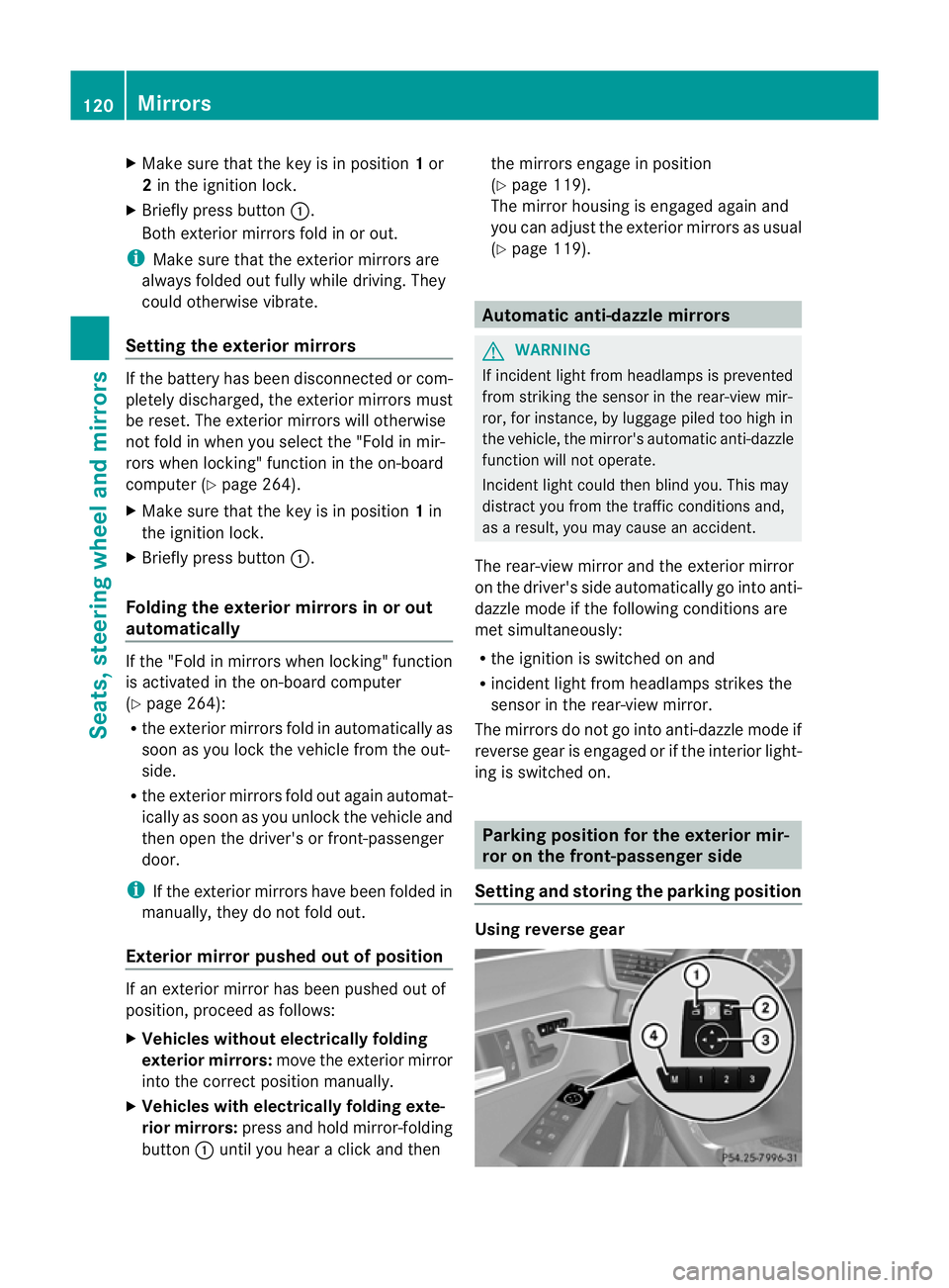
X Briefly press button :.
Both exterior mirrors fold in or out.
i Make sure that the exterior mirrors are
always folded out fully while driving. They
could otherwise vibrate.
Setting the exterior mirrors If the battery has been disconnected or com-
pletely discharged, the exterior mirrors must
be reset. The exterior mirrors will otherwise
not fold in when you select the "Fold in mir-
rors when locking" function in the on-board
computer (Y page 264).
X Make sure that the key is in position 1in
the ignition lock.
X Briefly press button :.
Folding the exterior mirrors in or out
automatically If the "Fold in mirrors when locking" function
is activated in the on-board computer
(Y
page 264):
R the exterior mirrors fold in automatically as
soon as you lock the vehicle from the out-
side.
R the exterior mirrors fold out again automat-
ically as soon as you unlock the vehicle and
then open the driver's or front-passenger
door.
i If the exterior mirrors have been folded in
manually, they do not fold out.
Exterior mirror pushed out of position If an exterior mirror has been pushed out of
position, proceed as follows:
X
Vehicles without electrically folding
exterior mirrors: move the exterior mirror
into the correct position manually.
X Vehicles with electrically folding exte-
rior mirrors: press and hold mirror-folding
button :until you hear a click and then the mirrors engage in position
(Y
page 119).
The mirror housing is engaged again and
you can adjust the exterior mirrors as usual
(Y page 119). Automatic anti-dazzle mirrors
G
WARNING
If incident light from headlamps is prevented
from striking the sensor in the rear-view mir-
ror, for instance, by luggage piled too high in
the vehicle, the mirror's automatic anti-dazzle
function will not operate.
Incident light could then blind you. This may
distract you from the traffic conditions and,
as a result, you may cause an accident.
The rear-view mirror and the exterior mirror
on the driver's side automatically go into anti-
dazzle mode if the following conditions are
met simultaneously:
R the ignition is switched on and
R incident light from headlamps strikes the
sensor in the rear-view mirror.
The mirrors do not go into anti-dazzle mode if
reverse gear is engaged or if the interior light-
ing is switched on. Parking position for the exterior mir-
ror on the front-passenger side
Setting and storing the parking position Using reverse gear120
MirrorsSeats, steering wheel and mirrors
Page 222 of 457
could otherwise endanger yoursel
fand oth-
ers. G
WARNING
Unde rthe following circumstances, the
reversing camera will not function, or will
function in a limited manner:
R if the tailgate is open
R in heavy rain, snow or fog
R at night or in very dark places
R if the camera is exposed to very bright light
R if the area is lit by fluorescent light or LED
lighting (the display may flicker)
R if there is a sudden change in temperature,
e.g. when driving into a heated garage in
winter
R if the camera lens is dirty or obstructed
R if the rear of your vehicle is damaged. In this
event, have the camera position and setting
checked at a qualified specialist workshop.
Mercedes-Ben zrecommends that you use
a Mercedes-Benz Service Centre for this
purpose.
Do not use the reversing camera in these
types of situation .You could otherwise injure
others or damage objects and your vehicle
while you are parking.
The area behind the vehicle is displayed as a
mirror image, as in the rear-view mirror.
Activating the reversing camera X
Make sure that the key is in position 2in
the ignition lock.
X Make sure that the "Reversing camera"
function is selected in COMAND APS (see
the separate operating instructions for
COMAND APS).
X Engage reverse gear.
The area behind the vehicle is shown with
guide lines in the COMAND display. Guide lines in the COMAND display G
WARNING
Using the reversing camera can be dangerous
if you are colour blind or your ability to distin-
guish colours is impaired.
Only use the reversing camera if you can see
and distinguish between all the coloured
guide lines that are displayed by the reversing
camera in the COMAND display. G
WARNING
Please note that objects not at ground level
may appear to be further away than they
actually are. These include:
R the bumper of a vehicle that is parked
behind your vehicle
R a trailer drawbar
R the ball coupling of a trailer tow hitch
R the tail-end of a lorry
R slanted posts
The lines are only guides, not accurate meas-
urements of the distance to an obstacle.
Therefore, you should never pass the red line
when approaching an obstacle. You could oth-
erwise cause an accident and injure yourself
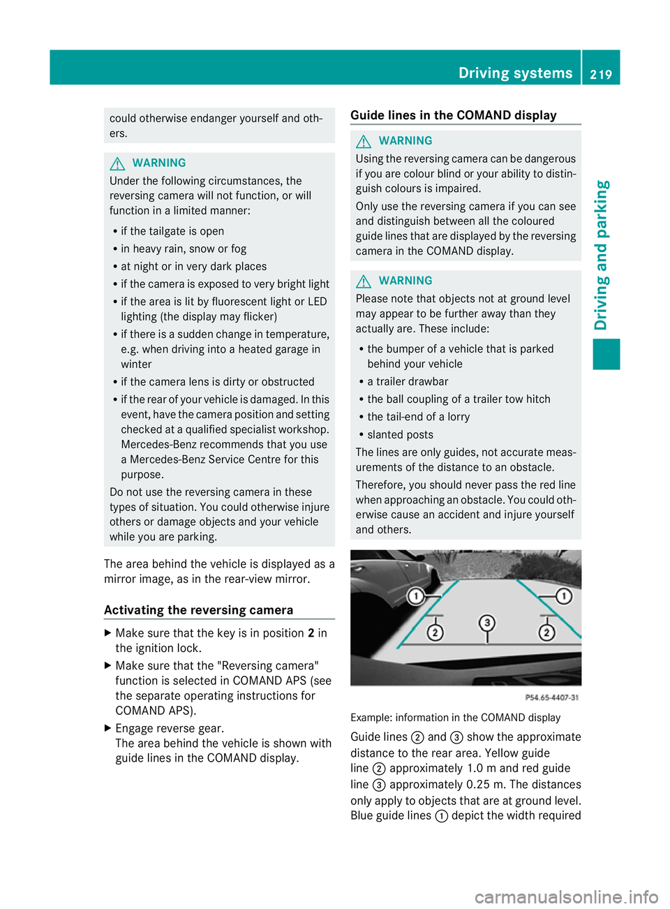
and others. Example: information in the COMAND display
Guide lines
;and =show the approximate
distance to the rear area. Yellow guide
line ;approximately 1.0 mand red guide
line =approximately 0.25 m. The distances
only apply to objects that are at ground level.
Blue guide lines :depict the width required Driving systems
219Driving and parking Z
Page 228 of 457
Problems with Night View Assist Plus
Problem Possible causes/consequences and
M Solutions
The picture quality of
Night View Assist Plus
has deteriorated. The windscreen wipers are smearing the windscreen.
X
Replace the wiper blades (Y page 139). The windscreen is smeared after the vehicle has been cleaned in
a car wash.
X
Cleant he windscreen (Y page 353). There is windscreen chip damage in the camera's field of vision.
X
Replace the windscreen. The windscreen is misted up on the inside.
X Demist the windscreen (Y page 149). The windscreen is iced up.
X
De-ice the windscreen (Y page 148). There is dirt on the inside of the windscreen.
X
Cleant he inside of the windscreen (Y page 353).Lane Tracking package
General notes The Lane Tracking package consists of Blind
Spot Assist (Y page 225) and Lane Keeping
Assist (Y page 227).
Blind Spot Assist Important safety notes
G
WARNING
Blind Spot Assist is only an aid designed to
assist driving. It may fail to detect some vehi-
cles and is no substitute for attentive driving.
Blind Spot Assist cannot detect road and traf-
fic conditions. It may fail to detect narrow
vehicles, such as motorcycles or bicycles, or
only detect them too late.
Monitoring may be affected by dirty sensors,
strong spray or poor visibility caused by snow,
rain or mist, for example. In this case, vehicles
are detected late or not at all. Always pay attention to traffic conditions and
your surroundings. Otherwise, you may fail to
recognise dangers in time, cause an accident
and injure yourself and others.
General notes
Blind Spot Assist uses a radar sensor system
to monitor the areas on both sides of your
vehicle. It supports you from speeds of
30 km/h. A warning display in the exterior
mirrors draws your attention to vehicles
detected in the monitored area. If you then
switch on the corresponding turn signal to
change lane, you will also receive an optical
and audible collision warning. For monitoring,
Active Blind Spot Assist uses sensors in the
rear bumper.
For Blind Spot Assist to assist you when driv-
ing, the radar sensor system must be activa-
ted (Y page 262) and operational.
The radar sensor system is automatically
deactivated near radio telescope facilities
(Y page 451). Driving systems
225Driving and parking Z
Page 332 of 457
X
Fold dow nthe rear seat armrest.
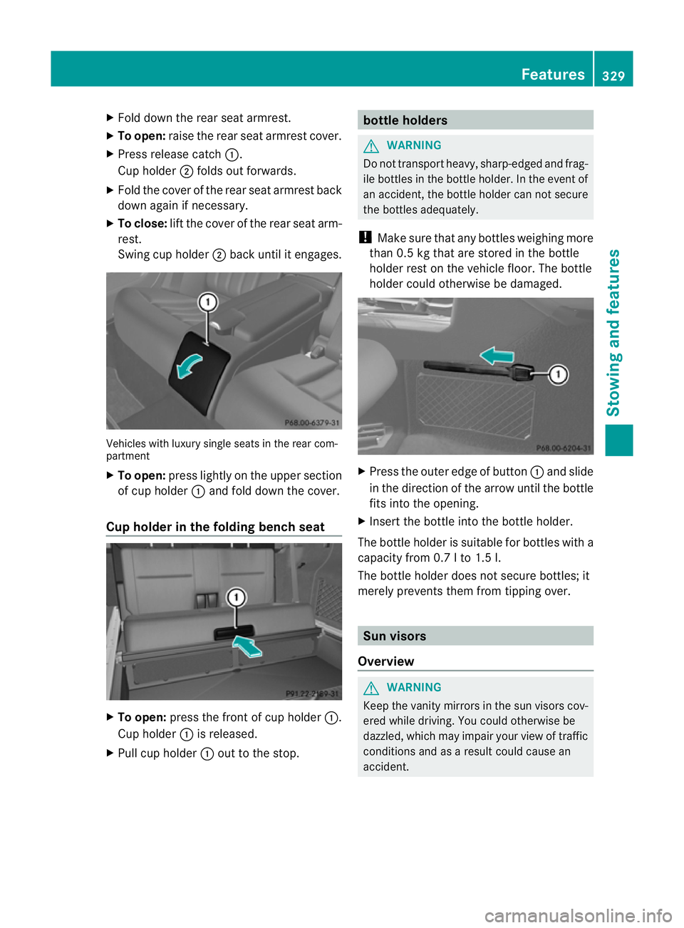
X To open: raise the rear seat armrest cover.
X Press release catch :.
Cup holder ;folds out forwards.
X Fold the cover of the rear seat armrest back
down again if necessary.
X To close: lift the cover of the rear seat arm-
rest.
Swing cup holder ;back until it engages. Vehicles with luxury single seats in the rear com-
partment
X To open: press lightly on the upper section
of cup holder :and fold down the cover.
Cup holder in the folding bench seat X
To open: press the front of cup holder :.
Cup holder :is released.
X Pull cup holder :out to the stop. bottle holders
G
WARNING
Do not transport heavy, sharp-edged and frag-
ile bottles in the bottle holder. In the event of
an accident, the bottle holder can not secure
the bottles adequately.
! Make sure that any bottles weighing more
than 0.5 kg that are stored in the bottle
holder rest on the vehicle floor. The bottle
holder could otherwise be damaged. X
Press the outer edge of button :and slide
in the direction of the arrow until the bottle
fits into the opening.
X Insert the bottle into the bottle holder.
The bottle holder is suitable for bottles with a
capacity from 0.7 l to 1.5 l.
The bottle holder does not secure bottles; it
merely prevents them from tipping over. Sun visors
Overview G
WARNING
Keep the vanity mirrors in the sun visors cov-
ered while driving. You could otherwise be
dazzled, which may impair your view of traffic
conditions and as a result could cause an
accident. Features
329Stowing and features Z
Page 338 of 457
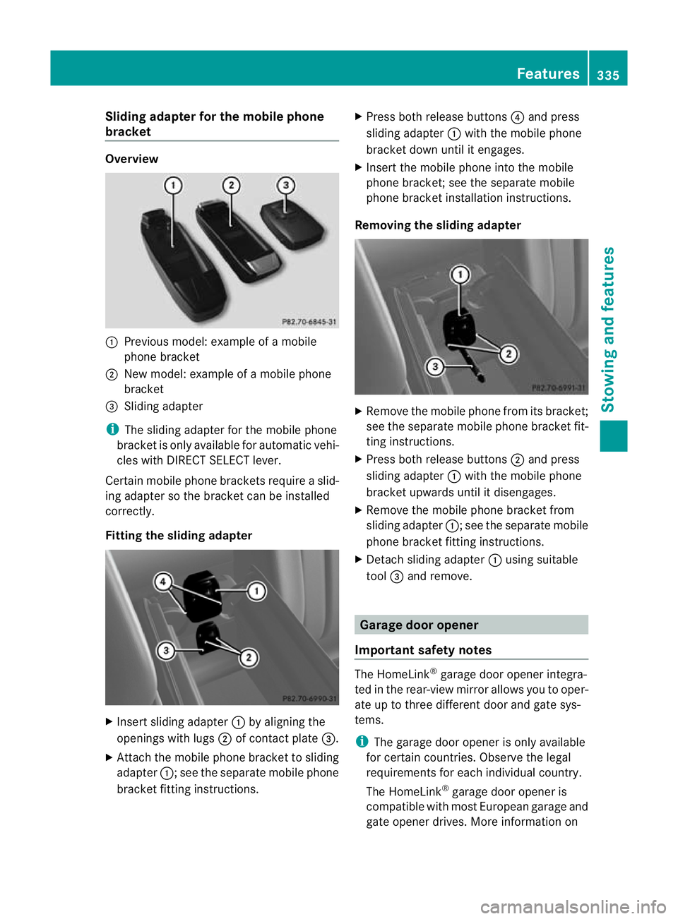
Sliding adapter for the mobile phone
bracket Overview
:
Previous model: example of a mobile
phone bracket
; New model: example of a mobile phone
bracket
= Sliding adapter
i The sliding adapter for the mobile phone
bracket is only available for automatic vehi-
cles with DIRECT SELECT lever.
Certain mobile phone brackets require a slid-
ing adapter so the bracket can be installed
correctly.
Fitting the sliding adapter X
Insert sliding adapter :by aligning the
openings with lugs ;of contact plate =.
X Attach the mobile phone bracket to sliding
adapter :; see the separate mobile phone
bracket fitting instructions. X
Press both release buttons ?and press
sliding adapter :with the mobile phone
bracket down until it engages.
X Insert the mobile phone into the mobile
phone bracket; see the separate mobile
phone bracket installation instructions.
Removing the sliding adapter X
Remove the mobile phone from its bracket;
see the separate mobile phone bracket fit-
ting instructions.
X Press both release buttons ;and press
sliding adapter :with the mobile phone
bracket upwards until it disengages.
X Remove the mobile phone bracket from
sliding adapter :; see the separate mobile
phone bracket fitting instructions.
X Detach sliding adapter :using suitable
tool =and remove. Garage door opener
Important safety notes The HomeLink
®
garage door opener integra-
ted in the rear-view mirror allows you to oper-
ate up to three different door and gate sys-
tems.
i The garage door opener is only available
for certain countries. Observe the legal
requirements for each individual country.
The HomeLink ®
garage door opener is
compatible with most European garage and
gate opener drives. More information on Features
335Stowing and features Z
Page 339 of 457
HomeLink
®
and/o rcompatible products is
available from:
R at a qualified specialised workshop
R the HomeLink ®
hotline
(0) 08000 466 354 65 (free of charge) or
+49 (0) 6838 907 277 (charges apply)
R on the Internet at:
http://www.homelink.com
Programming Programming buttons
G
WARNING
Only press the button on the integrated
garage door opener if there are no persons or
objects present within the sweep of the
garage door. Persons could otherwise be
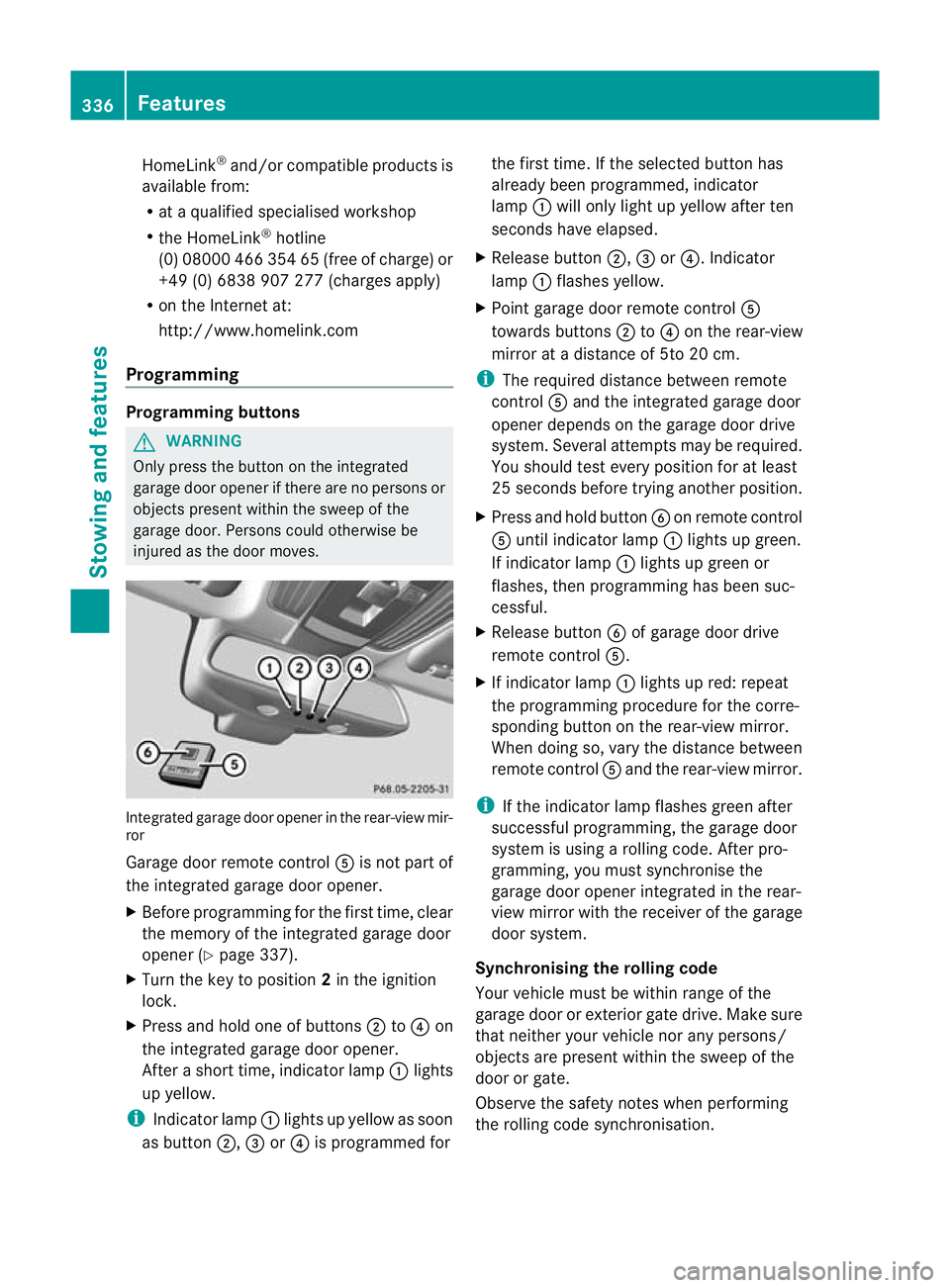
injured as the door moves. Integrated garage door opener in the rear-view mir-
ror
Garage door remote control
Ais not part of
the integrated garage door opener.
X Before programming for the first time, clear
the memory of the integrated garage door
opener (Y page 337).
X Turn the key to position 2in the ignition
lock.
X Press and hold one of buttons ;to? on
the integrated garage door opener.
After a short time, indicator lamp :lights
up yellow.
i Indicator lamp :lights up yellow as soon
as button ;,=or? is programmed for the first time. If the selected button has
already been programmed, indicator
lamp
:will only light up yellow after ten
seconds have elapsed.
X Release button ;,=or?. Indicator
lamp :flashes yellow.
X Point garage door remote control A
towards buttons ;to? on the rear-view
mirror at a distance of 5to 20 cm.
i The required distance between remote
control Aand the integrated garage door
opener depends on the garage door drive
system. Several attempt smay be required.
You should test every positio nfor at least
25 seconds before trying another position.
X Press and hold button Bon remote control
A until indicator lamp :lights up green.
If indicator lamp :lights up green or
flashes, then programming has been suc-
cessful.
X Release button Bof garage door drive
remote control A.
X If indicator lamp :lights up red: repeat
the programming procedure for the corre-
sponding button on the rear-view mirror.
When doing so, vary the distance between
remote control Aand the rear-view mirror.
i If the indicator lamp flashes green after
successful programming, the garage door
system is using a rolling code. After pro-
gramming, you must synchronise the
garage door opener integrated in the rear-
view mirror with the receiver of the garage
door system.
Synchronising the rolling code
Your vehicle must be within range of the
garage door or exterior gate drive. Make sure
that neither your vehicle nor any persons/
objects are present within the sweep of the
door or gate.
Observe the safety notes when performing
the rolling code synchronisation. 336
FeaturesStowing and features
Page 340 of 457
X
Turn the key to position 2in the ignition
lock.
X Press the programming button of the door
or gate drive (see the door or gate drive
operating instructions, e.g. under "Pro-
gramming of additional remote controls").
i Usually, you now have 30seconds to ini-
tiate the next step.
X Press previously programmed button ;,
= or? of the integrated garage door
opener until the door closes.
The rolling code synchronisation is then
complete.
Problems when programming
If you have problems when programming the
integrated garage door opener, please note
the following:
R Check the transmitter frequency of garage
door drive remote control A.This can usu-
ally be found on the back of the remote
control.
R Replace the batteries in garage door
remote control A.This increases the like-
lihood that garage door remote control A
will transmit a strong and precise signal to
the integrated garage door opener in the
rear-view mirror.
R When programming, hold remote control
A at varying distances and angles from the
button which you are programming. Try var-
ious angles at a distance between 5and
30 cm or at the same angle but at varying
distances.
R If there is another remote control for the
same garage door drive, perform the pro-
gramming steps again using this remote
control. Before performing these steps,
make sure that new batteries have been
fitted in garage door drive remote control
A.
R Note that some remote controls transmit
only for a limited period (the indicator lamp
on the remote control goes out). Press but- ton
Bon remote control Aagain before
transmission ends.
R Align the aerial cable of the garage door
opener unit. This can improve signal recep-
tion/transmission.
Opening or closing the garage door Once programmed, the integrated garage
door opener will assume the function of the
garage door system's remote control. Please
also read the operating instructions for the
garage door system.
X
Turn the key to position 2in the ignition
lock.
X Press button ;,=or? which you have
programmed to operate the garage door.
Garage door system with a fixed code: indi-
cator lamp :lights up green.
Garage door system with a rolling code:
indicator lamp :flashes green.
i The transmitter will transmit a signal for
as long as the button is pressed. The trans-
mission is halted after a maximum of ten
seconds and indicator lamp :lights up
yellow. Press button ;,=or? again if
necessary.
Clearing the memory X
Turn the key to position 2in the ignition
lock.
X Press buttons ;and ?.
The indicator lamp lights up yellow.
X Press and hold buttons ;and ?until the
indicator lamp turns green.
i Make sure that you clear the memory of
the integrated garage door opener before
selling the vehicle. Features
337Stowing and features Z