2012 MERCEDES-BENZ CLS SHOOTING BRAKE fuses
[x] Cancel search: fusesPage 13 of 405
EBD (electronic brake force distri-
bution)
Display message ............................ 252
Function/notes ................................ 69
ECO display
Function/notes ............................. 167
On-board computer .......................231
ECO start/stop function
Deactivating/activating .................152
General information .......................150
Electrical fuses
see Fuses
Electronic Stability Program
see ESP ®
(Electroni cStability Program)
Electronic Traction System
see ETS/4ETS (Electronic Trac-
tionS ystem)
Emergency key
Unlocking the driver's door ..............84
Emergency key element
Function/notes ................................ 78
Locking vehicle ................................ 84
Emergency release
Driver's door .................................... 84
Fuel filler fla p................................. 163
Emergency spare wheel
Important safety notes ..................377
Inflating the collapsible spare
wheel ............................................. 378
Points to remember .......................377
Removing ....................................... 377
Storage location ............................ 377
Stowing .......................................... 378
Technical data ............................... 380
Emergency unlocking
Tailgate ............................................ 88
Vehicle ............................................. 84
Engine
Display message ............................ 259
ECO start/stop function ................150
Engine number ............................... 385
Jump-starting ................................. 344
Running irregularl y......................... 153
Starting problems ..........................153
Starting the engine with the key ....149
Starting with KEYLESS GO .............149
Stopping ........................................ 166Tow-starting (vehicle) ..................... 349
Warning lamp (engine diagnos-
tics)
............................................... 284
Engine electronics
Notes ............................................. 383
Problem (fault) ............................... 153
Engine oil
Additives ........................................ 392
Checking the oil level ..................... 321
Checking the oil level using the
dipstick .......................................... 322
Display message ............................ 260
Filling capacity ............................... 391
Notes about oil grades ................... 391
Notes on oil level/consumption ....321
Temperature (on-board computer) .246
Topping up ..................................... 322
Viscosity ........................................ 392
Environmental protection
Returning an end-of-life vehicle .......22
ESP ®
(Electronic Stability Pro-
gram) AMG menu (on-board computer) ...246
Deactivating/activating (AMG
vehicles) .......................................... 68
Deactivating/activating (except
AMG vehicles) ................................ 237
Deactivating/activating (notes;
except AMG vehicles) ......................67
Display message ............................ 250
ETS/4ETS ........................................ 67
Function/notes ................................ 66
Important safety guidelines .............66
Trailer stabilisatio n.......................... 69
Warning lamp ................................. 281
ETS/4ETS (Electronic Traction Sys-
tem) ...................................................... 67
Exhaus tpipe (cleaning instruc-
tions) .................................................. 329
Exterior lighting Settings options ............................ .114
see Lights
Exterior mirrors
Adjusting ....................................... 108
Anti-dazzle mode (automatic) ........109
Folding in/ou t(automatically) .......109
Folding in/ou t(electrically) ...........109 10
Index
Page 14 of 405
Folding in whe
nlocking (on-board
computer) ...................................... 245
Out of position (troubleshooting) ...109
Parking position ............................. 110
Resetting ....................................... 109
Storing settings (memory func-
tion) ............................................... 111F
Faul tmessage
see Display messages
Filler cap
see Fuel filler flap
Fire extinguisher ............................... 335
First-aid kit ......................................... 334
Fitting awheel
Removing awheel .......................... 365
Fitting wheels
Fitting awheel ............................... 366
Lowering the vehicle ......................366
Raising the vehicle .........................364
Securing the vehicle against roll-
ing away ........................................ 363
Flat tyre
MOExtended tyres .........................337
Preparing the vehicle .....................336
TIREFIT kit ...................................... 338
Floormat ............................................ .317
Foglamps (extende drange) .............. 120
Frequencies Garage door opener .......................314
Mobile phone ................................. 383
Two-way radio ................................ 383
Front foglamps
Display message ............................ 257
Fuel
Additives ........................................ 389
Consumption information ..............390
Consumption statistics ..................231
Displaying the current consump-
tion ................................................ 231
Displaying the range ......................231
Fuel gauge ............................... 30, 227
Grade (petrol) ................................ 387
Important safety notes ..................386
Notes for AMG vehicles .................388
Problem (malfunction) ...................164Quality (diesel
)............................... 389
Refuelling ...................................... .161
Tank content/reserve fuel .............387
Fuel filler flap
Emergency release ........................163
Opening/closing ............................ 162
Fuel filte r(white display message) .261
Fuel level Calling up the range (on-board
computer) ...................................... 231
Gauge ...................................... 30, 227
Fuel reserve
see Fuel
Fuel tank
Capacity ........................................ 387
Problem (malfunction) ...................164
Fuse allocation chart (vehicle tool
kit) ...................................................... 335
Fuses Allocation chart ............................. 350
Before changing ............................. 350
Fuse box in the boot ......................351
Fuse box in the engine compart-
ment .............................................. 350
Fuse box in the luggage compart-
ment .............................................. 351
Important safety notes ..................350 G
Garage door opener Clearing the memory .....................313
Frequencies ................................... 314
Important safety notes ..................311
Opening/closing the garage door ..313
Programming (button in the rear-
view mirror) ................................... 312
Gear indicator (on-board com-
puter) ................................................. .246
Gearshift program SETUP (on-board computer) ..........246
Genuine Mercedes-Benz parts .........382
Glove compartment ..........................291 Index
11
Page 184 of 405
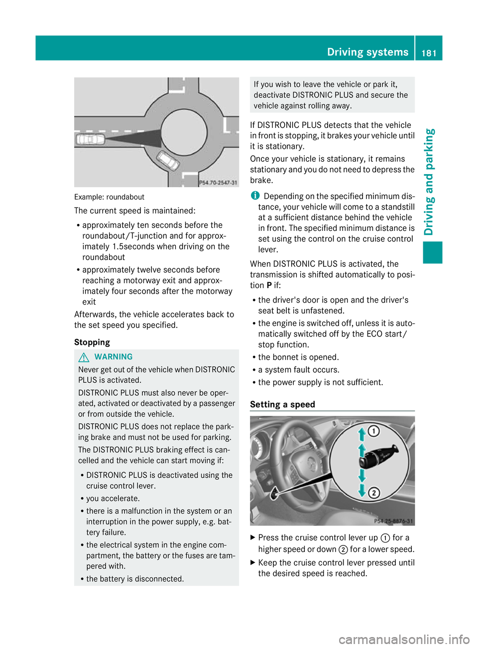
Example: roundabout
The current speed is maintained:
R
approximately ten seconds before the
roundabout/T-junction and for approx-
imately 1.5seconds when driving on the
roundabout
R approximately twelve seconds before
reaching a motorway exi tand approx-
imately fou rseconds after the motorway
exit
Afterwards, the vehicle accelerates back to
the set speed you specified.
Stopping G
WARNING
Never get out of the vehicle when DISTRONIC
PLUS is activated.
DISTRONIC PLUS must also never be oper-
ated, activated or deactivated by a passenger
or from outside the vehicle.
DISTRONIC PLUS does not replace the park-
ing brake and must not be used for parking.
The DISTRONIC PLUS braking effect is can-
celled and the vehicle can start moving if:
R DISTRONIC PLUS is deactivated using the
cruise control lever.
R you accelerate.
R there is a malfunction in the system or an
interruption in the power supply, e.g. bat-
tery failure.
R the electrical system in the engine com-
partment, the battery or the fuses are tam-
pered with.
R the battery is disconnected. If you wish to leave the vehicle or park it,
deactivate DISTRONIC PLUS and secure the
vehicle against rolling away.
If DISTRONIC PLUS detects that the vehicle
in fron tis stopping, it brakes your vehicle until
it is stationary.
Once your vehicle is stationary, it remains
stationary and you do not need to depress the
brake.
i Depending on the specified minimum dis-
tance, your vehicle will come to a standstill
at a sufficient distance behind the vehicle
in front.T he specified minimum distance is
set using the control on the cruise control
lever.
When DISTRONIC PLUS is activated, the
transmission is shifted automatically to posi-
tion Pif:
R the driver's door is open and the driver's
seat belt is unfastened.
R the engine is switched off, unless it is auto-
matically switched off by the ECO start/
stop function.
R the bonnet is opened.
R a system fault occurs.
R the power supply is not sufficient.
Setting aspeed X
Press the cruise control lever up :for a
highe rspeed or down ;for a lower speed.
X Keep the cruise control lever pressed until
the desired speed is reached. Driving systems
181Driving and parking Z
Page 189 of 405
HOLD function
General notes The HOLD function can assist the drive
rinthe
following situations:
R when pulling away, especially on steep
slopes
R when manoeuvring on steep slopes
R when waiting in traffic
The vehicle is kept stationary without the
driver having to depress the brake pedal.
The braking effect is cancelled and the HOLD
function is deactivated when you depress the
accelerator pedal to pull away.
Activation conditions You can activate the HOLD function if:
R
the vehicle is stationary.
R the engine is running or if it has been auto-
matically switched off by the ECO start/
stop function.
R the driver's door is closed or if your seat
belt is fastened.
R the parking brake is released.
R the bonnet is closed.
R the transmission is in position D,Ror N.
R DISTRONIC PLUS is deactivated.
Activating the HOLD function G
WARNING
The vehicle's brakes are applied when the
HOLD function is activated. For this reason,
deactivate the HOLD function if the vehicle is
to be set in motion by other means (e.g. in a
car wash or by towing). X
Make sure that the activation conditions
are met.
X Depress the brake pedal.
X Quickly depress the brake pedal further
until ë appears in the multifunction dis-
play.
The HOLD function is activated. You can
release the brake pedal.
i If depressing the brake pedal the first
time does not activate the HOLD function,
wait briefly and then try again.
Deactivating the HOLD function G
WARNING
Never get out of the vehicle when the HOLD
function is activated.
The HOLD function must never be operated
or deactivated by a passenger or from outside
the vehicle.
The HOLD function does not replace the park-
ing brake and must not be used for parking.
The braking effect of the HOLD function is
cancelled and the vehicle could roll away if:
R the HOLD function is deactivated by
depressing the accelerator pedal or the
brake pedal.
R there is a malfunction in the system or an
interruption in the power supply, e.g. bat-
tery failure.
R the electrical system in the engine com-
partment, the battery or the fuses are tam-
pered with.
R the battery is disconnected.
If you leave the vehicle or park it, deactivate
the HOLD function and secure the vehicle
against rolling away.
The HOLD function is deactivated automati-
cally if:
R you accelerate and the transmission is in
position Dor R.
R you shift the transmission to position P.186
Driving systemsDriving and parking
Page 261 of 405
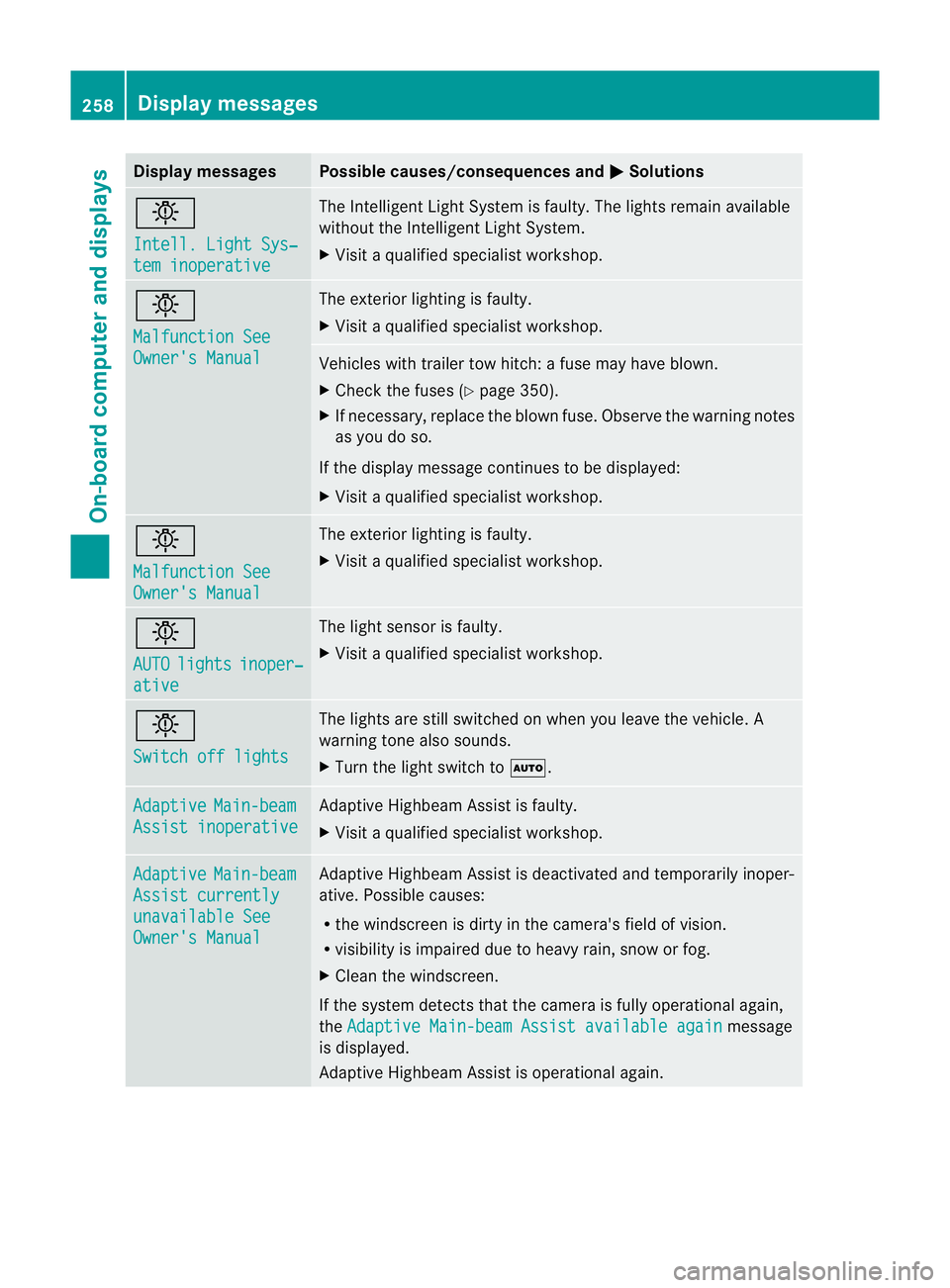
Display messages Possible causes/consequences and
M Solutions
b
Intell. Light Sys‐
tem inoperative The Intelligent Light Syste
mis faulty. The lights remain available
without the Intelligent Light System.
X Visit a qualified specialist workshop. b
Malfunction See
Owner's Manual The exterior lighting is faulty.
X
Visit a qualified specialist workshop. Vehicles with trailer tow hitch: a fuse may have blown.
X
Check the fuses (Y page 350).
X If necessary, replace the blown fuse. Observe the warning notes
as you do so.
If the display message continues to be displayed:
X Visit a qualified specialist workshop. b
Malfunction See
Owner's Manual The exterior lighting is faulty.
X
Visit a qualified specialist workshop. b
AUTO
lights inoper‐
ative The light sensor is faulty.
X
Visit a qualified specialist workshop. b
Switch off lights The lights are still switched on when you leave the vehicle. A
warning tone also sounds.
X
Turn the light switch to Ã.Adaptive Main-beam
Assist inoperative Adaptive Highbeam Assist is faulty.
X
Visit a qualified specialist workshop. Adaptive Main-beam
Assist currently
unavailable See
Owner's Manual Adaptive Highbeam Assist is deactivated and temporarily inoper-
ative. Possible causes:
R
the windscreen is dirty in the camera's field of vision.
R visibility is impaired due to heavy rain, snow or fog.
X Cleant he windscreen.
If the system detects that the camera is fully operational again,
the Adaptive Main-beam Assist available again message
is displayed.
Adaptive Highbeam Assist is operational again. 258
Display messagesOn-board computer and displays
Page 336 of 405
Useful information
............................334
Where will I find...? ...........................334
Flat tyre ............................................. 336
Batter y(vehicle) ................................ 340
Jump-starting .................................... 344
Towing and tow-starting ..................346
Electrical fuses ................................. 350 333Breakdown assistance
Page 353 of 405
Electrical fuses
Important safety notes
G
WARNING
Only use fuses that have been approved for
Mercedes-Ben zvehicles and which have the
correct fuse rating for the systems con-
cerned. Do not attempt to repair or bridge
faulty fuses. Using fuses which have not been
approved or attempting to repair or bridge
faulty fuses could cause the fuse to be over-
loaded and result in a fire. Have the cause
traced and rectified at a qualified specialist
workshop.
! Only use fuses that have been approved
for Mercedes-Benz vehicles and which
have the correct fuse rating for the system
concerned. Otherwise, components or sys-
tems could be damaged.
The fuses in your vehicle serve to close down
faulty circuits. If afuse blows, all the compo-
nents on the circuit and their functions stop
operating.
Blown fuses must be replace dwith fuses of
the same rating, which you can recognise by
the colour and fuse rating. The fuse ratings
are listed in the fuse allocation chart.
If the newly inserted fuse also blows, have the
cause traced and rectified at a qualified spe-
cialist workshop, e.g. a Mercedes-Benz
Service Centre. Before replacing a fuse
X Secure the vehicle against rolling away
(Y page 165).
X Switch off all electrical consumers.
X Turn the key to position 0in the ignition
lock and remove it (Y page 147).
or
X On vehicles with KEYLESS-GO, make sure
the ignition is switched off (Y page 147).
All indicator lamps in the instrumen tcluster
must be off. The fuses are located in various fuse boxes:
R
fuse box in the engine compartmen tonthe
left-hand side of the vehicle, when viewed
in the direction of travel
R CLS Coupé: fuse box in the boot on the
right-hand side of the vehicle, when viewed
in the direction of travel
R CLS Shooting Brake: fuse box in the lug-
gage compartmentont he right-hand side
of the vehicle, when viewed in the direction
of travel
CLS Coupé: the fuse allocation chart is loca-
ted in the vehicle tool kit in the stowage com-
partment under the boot floor (Y page 335).
CLS Shooting Brake: the fuse allocation
chart is located in the vehicle tool kit in the
stowage compartmentu nderthe luggage
compartment floor (Y page 335). Fuse box in the engine compartment
G
WARNING
Make sure that the windscreen wipers are
turned off and the key is pulled out of the igni-
tion lock before you open the cover of the fuse
box. Otherwise, the windscreen wipers and
the wiper rods above the cover could be set
in motion. This could lead to you or others
being injured by the wiper rods.
! Make sure that no moisture can enter the
fuse box when the cover is open.
! When closing the cover, make sure that it
is lying correctly on the fuse box. Moisture
seeping in or dirt could otherwise impair
the operation of the fuses.
X Make sure that the windscreen wipers are
switched off.
X Open the bonnet. 350
Electrical fusesBreakdown assistance
Page 354 of 405
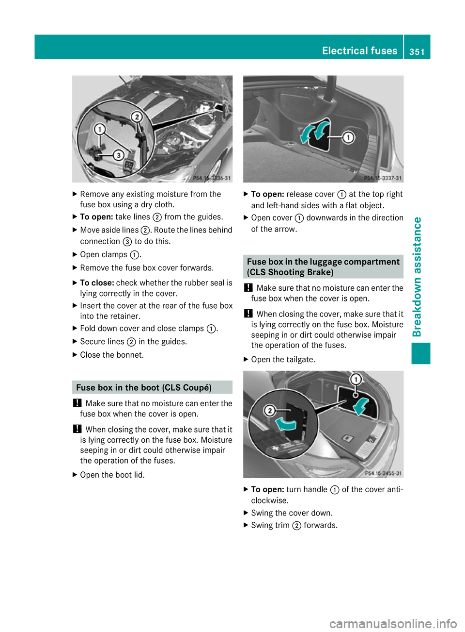
X
Remove any existing moisture from the
fuse box using a dry cloth.
X To open: take lines ;from the guides.
X Move aside lines ;.Route the lines behind
connection =to do this.
X Open clamps :.
X Remove the fuse box cover forwards.
X To close: check whether the rubber seal is
lying correctly in the cover.
X Insert the cover at the rear of the fuse box
into the retainer.
X Fold down cover and close clamps :.
X Secure lines ;in the guides.
X Close the bonnet. Fuse box in the boot (CLS Coupé)
! Make sure that no moisture can enter the
fuse box when the cover is open.
! When closing the cover, make sure that it
is lying correctly on the fuse box. Moisture
seeping in or dirt could otherwise impair
the operation of the fuses.
X Open the boot lid. X
To open: release cover :at the top right
and left-hand sides with a flat object.
X Open cover :downwards in the direction
of the arrow. Fuse box in the luggage compartment
(CLS Shooting Brake)
! Make sure that no moisture can enter the
fuse box when the cover is open.
! When closing the cover, make sure that it
is lying correctly on the fuse box. Moisture
seeping in or dirt could otherwise impair
the operation of the fuses.
X Open the tailgate. X
To open: turn handle :of the cover anti-
clockwise.
X Swing the cover down.
X Swing trim ;forwards. Electrical fuses
351Breakdown assistance Z