Page 49 of 295

1
KNOWING YOUR CAR47
IMPORTANT The engine immobilizer function is guar-
anteed by the Lancia CODE, which is automatically ac-
tivated when the ignition key is extracted from the starter
device.
TURNING THE ALARM ON
With the doors and bonnet closed and the ignition key
either turned to STOP or removed, point the key with the
remote control towards the vehicle and press and release
button
Á.
Excluding some markets, the system produces an acoustic
warning (beep) and enables door locking.
The switching on of the alarm is preceded by a self-di-
agnosis stage: if a fault is detected, the system emits a new
acoustic signal together with the display of a message (see
“Panel warning lights” chapter).
In this case switch off the alarm by pressing
Ë, check that
all the doors, bonnet and tailgate are closed correctly;
then switch the alarm back on by pressing
Á.
If a door or the bonnet is not properly shut, it will be ex-
cluded from the testing by the alarm system.
If the alarm emits an acoustic signal even when the doors,
bonnet and tailgate are correctly closed, a failure has oc-
curred in system operation. Contact a Lancia Dealership.IMPORTANT Centrally locking the doors using the metal
insert on the key does not activate the alarm.
IMPORTANT The alarm is adapted to meet requirements
in various countries.
TURNING THE ALARM OFF
Press button
Ëon the key with the remote control.
The following operations are performed (excluding some
markets):
❍the direction indicators flash briefly twice;
❍two brief acoustic signals are emitted (“BEEP”);
❍the doors are unlocked.
IMPORTANT Activating the central opening using the
key’s metal insert does not turn the alarm off.
Page 50 of 295

48KNOWING YOUR CAR
VOLUMETRIC/ANTI-LIFT PROTECTION
To guarantee the correct operation of the protection sys-
tem it is advisable to shut all the side windows and the
sun roof (for versions/markets where provided).
If necessary, the function can be turned off (if, for ex-
ample, you are leaving an animal in the car) by pressing
button A-fig. 14, located in the front courtesy light, be-
fore activating the alarm itself.
When the function is disabled, this is indicated by the
LED on the button flashing for several seconds. Any dis-
abling of the volume sensing/anti-lift protection must be
repeated each time the instrument panel is switched off.
BREAK IN ATTEMPT INDICATION
Any break in attempt is indicated by the
Ywarning light
(or symbol in the display) lighting up, together with
a message shown in the display (see “Instrument panel
warning lights” chapter).DISABLING THE ALARM
To turn the alarm off completely (for example, if the ve-
hicle is not being used for a long time) the vehicle must
be closed by turning the metal insert in the key in the lock
without using the remote control.
IMPORTANT If the battery of the key with the remote
control runs out or the system fails, the alarm can be
switched off by placing the key in the ignition switch and
turning it to MAR.
fig. 14L0E0153m
Page 51 of 295

1
KNOWING YOUR CAR49
IGNITION DEVICE
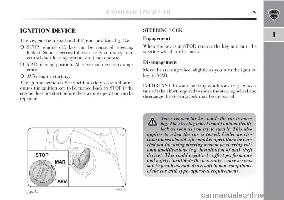
The key can be turned to 3 different positions fig. 15:
❍STOP: engine off, key can be removed, steering
locked. Some electrical devices (e.g. sound system,
central door locking system, etc.) can operate.
❍MAR: driving position. All electrical devices can op-
erate.
❍AVV: engine starting.
The ignition switch is fitted with a safety system that re-
quires the ignition key to be turned back to STOP if the
engine does not start before the starting operation can be
repeated.STEERING LOCK
Engagement
When the key is at STOP, remove the key and turn the
steering wheel until it locks.
Disengagement
Move the steering wheel slightly as you turn the ignition
key to MAR.
IMPORTANT In some parking conditions (e.g.: wheels
turned) the effort required to move the steering wheel and
disengage the steering lock may be increased.
fig. 15L0E0107m
Never remove the key while the car is mov-
ing. The steering wheel would automatically
lock as soon as you try to turn it. This also
applies to when the car is towed. Under no cir-
cumstances should aftermarket operations be car-
ried out involving steering system or steering col-
umn modifications (e.g. installation of anti-theft
device). This could negatively affect performance
and safety, invalidate the warranty, cause serious
safety problems and also result in non-compliance
of the car with type-approval requirements.
Page 52 of 295
50KNOWING YOUR CAR
SEATS
FRONT SEATS
Lengthwise direction adjustment fig. 16
Lift the lever A and push the seat forwards or backwards:
in the driving position your arms should rest on the rim
of the steering wheel.
Backrest angle adjustment fig. 16
Turn knob B.
All adjustments on the front and rear seats
must be made with the car stationary.
After releasing the adjustment levers always
check that the seat is locked into place by try-
ing to move it back and forth. Failure to lock
the seat in place could result in the seat moving sud-
denly and the driver losing control of the car.
fig. 16L0E0008m
Page 53 of 295

1
KNOWING YOUR CAR51
Height adjustment fig. 16
Operate lever C to raise or lower the rear part of the seat
cushion to improve comfort.
Lumbar adjustment (driver’s seat) fig. 16
The position of the back against the seat backrest is ad-
justed by turning knob D.
FRONT SEATS WITH ELECTRIC ADJUSTMENT
fig. 17(for versions/markets where provided
The adjustment is possible with the ignition ON or for up
to 1 minute with the ignition key turned to OFF or ex-
tracted.
When the front doors are opened the seat on the side of
the door that has been opened can be moved for about
3 minutes or until the door is closed.
The controls for seat adjustment are:
Multifunction control A:
❍seat height adjustment;
❍lengthwise seat movement.
Multifunction control B:
❍backrest angle adjustment;
❍backrest lumbar adjustment.Seat heating fig. 17
(for versions/markets where provided)
With the key turned to MAR, press buttons
Cto switch
the function on/off.
When the function is enabled, the LED on the button
turns on.
fig. 17L0E0009m
Page 54 of 295
52KNOWING YOUR CAR
REAR SEATS
Backrest angle adjustment
Lift lever A-fig. 18/a (one each side) for backrest angle
adjustment, for the left or right part of the backrest (to
aid this operation, slightly move the seat forwards using
lever B).
Rear seat movement
(for versions/markets where provided)
The rear seats can be moved backwards and forwards (by
80 mm). To move the seats backwards or forwards op-
erate the levers B (one on each side).
fig. 18/aL0E0010m
“Fixed” type rear seats
In some versions, rear seats are “fixed” type and the
backrest angle adjustment is possible if the luggage com-
partment is extended. Use lever A-fig. 18/b (one each
side) for backrest angle adjustment.
When repositioning the rear backrest during
its movement, check that it has coupled cor-
rectly, grasping the backrest at the top and
shaking it.
fig. 18/bL0E0231m
Before tilting the backrests, make sure that
the seat belts are fully stretched, without any
twisting.
Page 55 of 295

1
KNOWING YOUR CAR53
HEADREST
FRONT HEAD RESTRAINTS fig. 19
Head restraints are height adjustable; operate as follows.
❍Upwards adjustment: lift the head restraint until it
locks.
❍Downward adjustment, press the button A and lower
the head restraint.
fig. 19L0E0011m
To extract the rear head restraints press buttons B and
C simultaneously and release them upwards.
IMPORTANT If the rear seats are used, always set the
head restraints in the “completely raised” position.
All adjustments must be carried out only
with the vehicle stationary and engine off.
Head restraints must be adjusted so that the
head, rather than the neck, rests on them. Only in
this case they can protect your head correctly. To
make the best use of the head restraint protection,
adjust the seat back to keep a straight back, with
the head as close as possible to its restraint.
REAR HEAD RESTRAINTS fig. 19
(for versions/markets where provided)
Depending on the versions, rear head restraints can be
“fixed” or height adjustable type.
Height-adjustable head restraints:
❍Upwards adjustment: press the button B and lift the
head restraint until it locks.
❍Downward adjustment, press the button B and lower
the head restraint.
Page 56 of 295
54KNOWING YOUR CAR
STEERING WHEEL
It can be adjusted vertically (and axially).
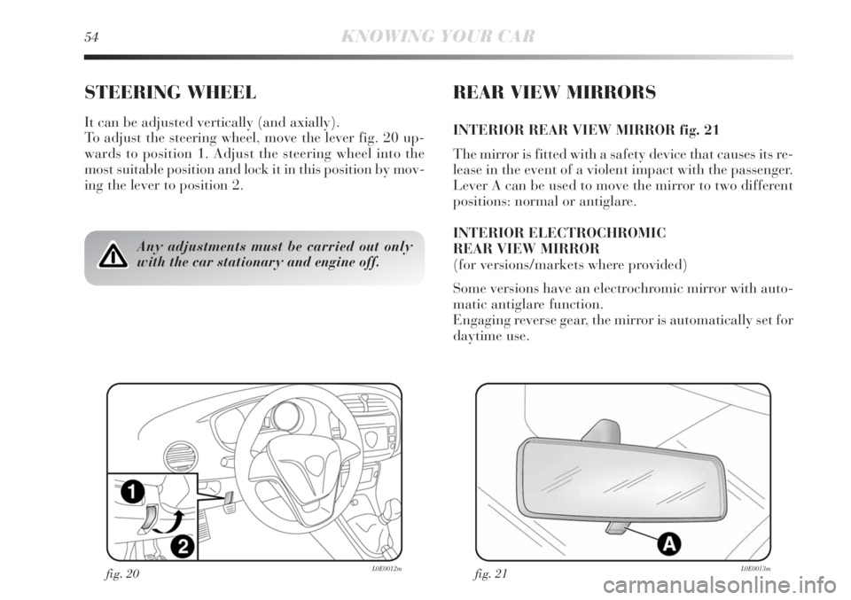
To adjust the steering wheel, move the lever fig. 20 up-
wards to position 1. Adjust the steering wheel into the
most suitable position and lock it in this position by mov-
ing the lever to position 2.
REAR VIEW MIRRORS
INTERIOR REAR VIEW MIRROR fig. 21
The mirror is fitted with a safety device that causes its re-
lease in the event of a violent impact with the passenger.
Lever A can be used to move the mirror to two different
positions: normal or antiglare.
INTERIOR ELECTROCHROMIC
REAR VIEW MIRROR
(for versions/markets where provided)
Some versions have an electrochromic mirror with auto-
matic antiglare function.
Engaging reverse gear, the mirror is automatically set for
daytime use.
Any adjustments must be carried out only
with the car stationary and engine off.
fig. 21L0E0013mfig. 20L0E0012m