Page 66 of 429

This section gives inf ormation about
the controls and displays that
contribute to the daily operation of
your vehicle. All the essential
controls are within easy reach............................
Control Locations . 60
............................
Instrument Panel . 61
..........
Instrument Panel Indicators . 62
.............................................
Gauges . 76
..............
Multi-Inf ormation Display .82
Controls Near the Steering
...........................................
Wheel . 93
........................
Multi-Control Lever . 94
........................................
Headlights . 95
...............
Headlight Control Dial . 95
........................................
Fog Lights . 97
........
Instrument Panel Brightness . 98
.................
Hazard Warning Button . 99
..........
Steering Wheel Adjustment . 99
................................................
Keys . 100
......................
Immobilizer System . 101
..............................
Ignition Switch . 102
....................................
Door Locks . 103
............
Childproof Door Locks . 104
Auto Door Locking/
..............................
Unlocking . 104
.....................
Remote Transmitter . 110
.....................
Dual-Action Tailgate . 113
...............................
In-Bed Trunk
. 116
...............................................
Seats . 119
..................................
Seat Heaters . 126 ............................
Power Windows . 128
.......................................
Moonroof . 131
...............................
Parking Brake . 132
...........................................
Mirrors . 133
.........
Interior Convenience Items . 135
.........................
Center Console . 136
.......
Console Compartments . 136
.........................
Cargo Hooks . 137
.....................
Beverage Holders . 137
..................................
Glove Box . 138
................................
Coat Hooks . 138
....................
Sunglasses Holder . 138
........
Accessory Power Sockets . 139
...................................
Sun Visor . 140
............................
Vanity Mirror . 140
........................
AC Power Outlet .141
...............................
Interior Lights . 142
.....................................
Bed Lights . 144
Instruments and Controls
Inst rument s and Cont rols
59
Main MenuINDEX
Page 68 of 429

�Î �Î�Î
�Î
�Î �Î
�Î �Î
On models without navigation system.
On models with navigation system.
The U.S. instrument panel is shown. Dif f erences f or the Canadian models are noted in the tex
t.
1:2:3: On RTS, RTL, and Touring models.
Instrument Panel
Inst rument s and Cont rols
61
CRUISE CONTROL
INDICATOR
(P.72)
(P.70)
(P.75)
(P.65)
(P.63) (P.63)
(P.63)
(P.69)(P.75) (P.82)/
INFORMATION
DISPLAY
MULTI-INFORMATION
DISPLAY
(P.77)
(P.67) (P.62)
SIDE AIRBAG OFF INDICATOR
(P.74)
(P.67)(P.66)
SECURITY SYSTEM INDICATOR (P.68)
HIGH BEAM
INDICATOR
(P.73)
(P.68)
ANTI-LOCK BRAKE SYSTEM
(ABS) INDICATOR
DAYTIME RUNNING LIGHTS
INDICATOR
WASHER LEVEL INDICATOR
(P.67) SEAT BELT REMINDER
INDICATOR
LOW FUEL INDICATOR (P.71)
(P.69)
DOOR AND TAILGATE OPEN INDICATOR
IN-BED TRUNK OPEN INDICATOR
A/T TEMPERATURE INDICATOR
BED LIGHTS ON INDICATOR
(P.74)
MALFUNCTION INDICATOR
LAMP
LOW OIL PRESSURE
INDICATOR
CHARGING SYSTEM
INDICATOR
PARKING BRAKE AND BRAKE
SYSTEM INDICATOR
BACK WINDOW OPEN
INDICATOR
VTM-4 INDICATOR
LOW TIRE PRESSURE INDICATOR/
TPMS INDICATOR
TIRE PRESSURE MONITORING SYSTEM
(TPMS) INDICATOR
LIGHTS ON INDICATOR
(P.75)
VEHICLE STABILITY ASSIST (VSA)
SYSTEM INDICATOR (P.70)
IMMOBILIZER SYSTEM
INDICATOR(P.66)
MESSAGE INDICATOR
(P.64)
CRUISE MAIN
INDICATOR
(P.67)
(P.67)
MAINTENANCE MINDER INDICATOR
VSA OFF INDICATOR (P.71) SUPPLEMENTAL RESTRAINT
SYSTEM (SRS) INDICATOR
(P.64)
2
1 3
2 1
Main MenuTable of Contents
Page 74 of 429
This indicator comes on with the
high beam headlights. For more
inf ormation, see page .
If this indicator comes on when the
ignition switch is turned to the ON
(II) position and the parking brake is
released, it means there is a problem
with a circuit. Have your vehicle
checked by your dealer.
If you see a ‘‘CHECK DRL
SYSTEM
Page 104 of 429
With the headlight control dial of f ,
the daytime running lights come on
when you turn the ignition switch to
the ON (II) position and release the
parkingbrake.Theyremainonuntil
you turn the ignition switch of f , even
if you set the parking brake.
The headlights revert to normal
operation when you turn them on
with the headlight control dial.If you see a ‘‘CHECK DRL
SYSTEM
Page 218 of 429

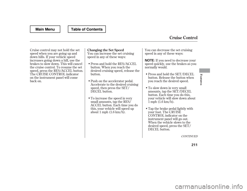
You can increase the set cruising
speed in any of these ways:You can decrease the set cruising
speed in any of these ways:
Press and hold the RES/ACCEL
button. When you reach the
desired cruising speed, release the
button.
Push on the accelerator pedal.
Accelerate to the desired cruising
speed, then press the SET/
DECEL button.
Cruise control may not hold the set
speed when you are going up and
down hills. If your vehicle speed
increases going down a hill, use the
brakes to slow down. This will cancel
thecruisecontrol.Toresumetheset
speed, press the RES/ACCEL button.
The CRUISE CONTROL indicator
on the instrument panel will come
back on.
To increase the speed in very
small amounts, tap the RES/
ACCEL button. Each time you do
this, your vehicle will speed up
about 1 mph (1.6 km/h). If you need to decrease your
speed quickly, use the brakes as you
normally would.
Tap the brake pedal lightly with
your f oot. The CRUISE
CONTROL indicator on the
instrument panel will go out.
When the vehicle slows to the
desired speed, press the SET/
DECEL button.
Press and hold the SET/DECEL
button. Release the button when
you reach the desired speed.
To slow down in very small
amounts, tap the SET/DECEL
button. Each time you do this,
your vehicle will slow down about
1 mph (1.6 km/h).
CONT INUED
Changing the Set Speed
Cruise Control
Features
211
NOTE:
Main MenuTable of Contents
Page 296 of 429
Make sure the parking brake is
f ully released bef ore driving away.
Driving with the parking brake
partially set can overheat or
damage the rear brakes.
Make sure the moonroof (if
equipped) and the windows are
closed.
Turn of f the lights.
Place any packages, valuables, etc.
in the cargo area in your vehicle or
the In-Bed Trunk, or take them
with you.
Lock the doors.
Check the indicator on the driver
Page 297 of 429

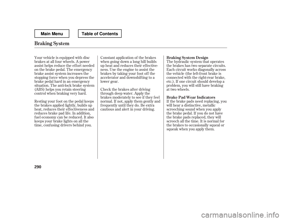
Your vehicle is equipped with disc
brakes at all f our wheels. A power
assist helps reduce the ef f ort needed
on the brake pedal. The emergency
brake assist system increases the
stopping f orce when you depress the
brake pedal hard in an emergency
situation. The anti-lock brake system
(ABS) helps you retain steering
control when braking very hard.
Resting your f oot on the pedal keeps
the brakes applied lightly, builds up
heat, reduces their ef f ectiveness and
reduces brake pad lif e. In addition,
f uel economy can be reduced. It also
keeps your brake lights on all the
time, conf using drivers behind you.Constant application of the brakes
when going down a long hill builds
up heat and reduces their ef f ective-
ness. Use the engine to assist the
brakes by taking your f oot of f the
accelerator and downshif ting to a
lower gear.
Check the brakes after driving
through deep water. Apply the
brakes moderately to see if they f eel
normal. If not, apply them gently and
f requently until they do. Be extra
cautious and alert in your driving.
The hydraulic system that operates
the brakes has two separate circuits.
Each circuit works diagonally across
the vehicle (the lef t-f ront brake is
connected with the right-rear brake,
etc.). If one circuit should develop a
problem, you will still have braking
at two wheels.
If the brake pads need replacing, you
will hear a distinctive, metallic
screeching sound when you apply
the brake pedal. If you do not have
the brake pads replaced, they will
screech all the time. It is normal f or
the brakes to occasionally squeal or
squeak when you apply them.
Braking System Design
Brake Pad Wear Indicators
Braking System
290
Main MenuTable of Contents
Page 309 of 429

�´
Trailer lights and equipment must
comply with f ederal, state, province/
territory, and local regulations.
Check trailer light requirements f or
the areas where you plan to tow, and
use only equipment designed f or
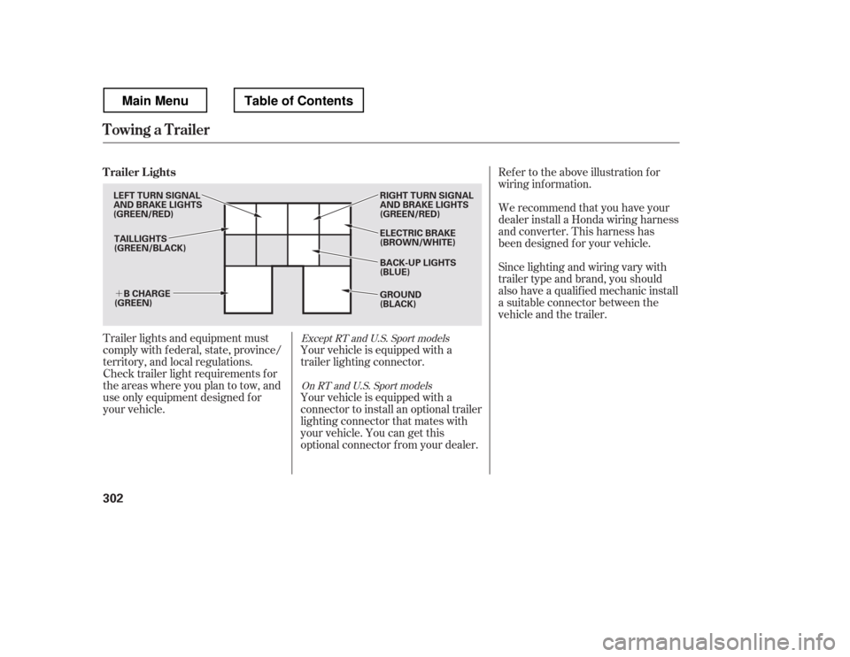
your vehicle.Ref er to the above illustration f or
wiring inf ormation.
We recommend that you have your
dealer install a Honda wiring harness
and converter. This harness has
been designed f or your vehicle.
Your vehicle is equipped with a
trailer lighting connector.
Your vehicle is equipped with a
connector to install an optional trailer
lighting connector that mates with
your vehicle. You can get this
optional connector f rom your dealer. Since lighting and wiring vary with
trailer type and brand, you should
also have a qualif ied mechanic install
a suitable connector between the
vehicle and the trailer.Except RT and U.S. Sport models
On RT and U.S. Sport models
Trailer Lights
Towing a Trailer
302
TAILLIGHTS
(GREEN/BLACK) ELECTRIC BRAKE
(BROWN/WHITE)
RIGHT TURN SIGNAL
AND BRAKE LIGHTS
(GREEN/RED) GROUND
(BLACK)
B CHARGE
(GREEN)
LEFT TURN SIGNAL
AND BRAKE LIGHTS
(GREEN/RED)
BACK-UP LIGHTS
(BLUE)
Main MenuTable of Contents