Page 257 of 294

.. The fault wheel will not fit ins ide the spa re
whee l wel l. Store it in the luggage compart
ment and secure it so that it does not slide
r=> page 59 .
.. Check the tire pres sure on the spare wheel
immediately after mounting it .
.. As soon as possible, have the
tightening
t o rqu es
on a ll wheel bolts checked with a
torque wrench . The correct tightening tor
que is 90 ft lb ( 120 Nm) .
.. Have the flat tire
re pl ac ed as soon as possi
ble.
(D Tips
- If you notice that the whee l bolts are
corroded and difficult to t urn w hile
changing a tire, they should be replaced
before you check the tightening torque .
- Drive at reduced speed until you have the
tightening torques checked .
- After changing a wheel, the tire pressure
in a ll four tires must be checked/cor rect
ed and the tire pressure monitoring indi
cator must be stored in the MMI
r=> page 251.
Decorative wheel covers
App lies to vehicles: with deco rat ive wheel cove rs
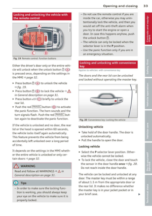
T h e decorativ e whe el covers must b e re moved
firs t to access the wheel bol ts.
Fi g. 186 Ch ang ing a w hee l: Remov ing the wheel cove r
Removing
.. Insert the hook (provided with the vehicle
tool kit) in the hole in the wheel hub cover .
.. Pu ll off the
dec orativ e whe el c over
r=> fig . 186.
What do I d o now ? 255
Wheels with wheel bolt caps
Applies to vehicles: wit h wheel bo lts with caps
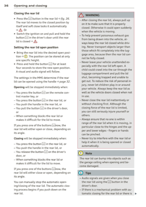
T he cops must be removed first from the
wheel bolts before the bolts con be un
screwed .
Fig . 1 87 Changin g a whee l: r emovi ng th e wheel bolt
c ap s
Removing
.. Push the pla stic clip (provided with the ve
hicle tool kit) over the wheel bolt cap unt il
the inner reta iners on the clip align with the
edge of the cove r.
.. Remove the cap w it h the
pl as tic clip (veh i
cle too l kit)
r::!:> fig . 187.
Refitting
.. Place the caps over the wheel bolts and
push them back on.
The caps are to protect and keep the wheel bolts clean.
Loosening and tightening the wheel
bolts
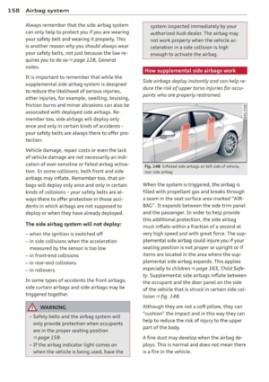
The wheel bolts must be loosened before rais
ing the vehicle .
Fig. 188 Changing a whee l: loosening t he w hee l bo lts ..
Page 258 of 294

256 What do I do now ?
Loo sening
.,. Slide the wheel wr ench onto the wheel bolt
as far as it will go .
.,. Take tight hold of the
end of the wrench
hand le and turn the wheel bolts
co unter
clock wise
about one single turn in the direc
t ion of arrow
c:;, fig. 188.
Tighten ing
.,. Slide the wheel wrench onto the whee l bolt
as far as it will go .
.,. Take tight hold of the
end of the wrench
hand le and turn each wheel bolt
clock wise
until it is seated.
_& WARNING
- Do not use force or hurry when changi ng
a whee l - you can cause the vehicle to slip
off the jack and cause ser ious persona l
injuries.
- Do not loosen the wheel bolts more than
one turn
before you raise the veh icle with
the jack. -You r isk an injury.
@ Tips
- Never use the hexagonal socket in the
handle of the screwdrive r to loosen or
tighten the wheel bo lts.
- If a wheel bolt is very tight, you may find
i t easier to loosen by ca refully p ush ing
down on the end of the wheel bolt
wrench w ith
one foot only. As yo u do so,
ho ld on to the car to keep your ba lance
and take care not to slip .
Raising the vehicle
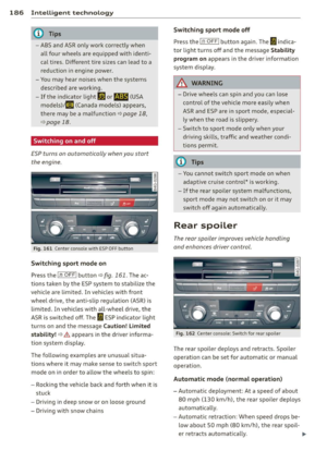
The vehicle must be lifted with the jock first
before the wheel can be removed .
Fig . 1 89 C hang ing a whee l: moun ting po in ts for th e
j ack
Fi g. 1 90 Close -up: prope r posit io ni ng o f jack
.,. Engage the p ar king brak e to prevent your
veh icle from rolling unintentionally .
.,. Move the
select or lever to p osition P .
.,. Posit ion the jack below the door s ill under
the
mounting point that is closest to the
wheel to be changed
c:;, fig . 189.
.,. Extend the ja ck u nder the lifting point on
t he door s ill until its arm is pos it ioned di
rectly under the lifting point
c:;, &_ .
.,. Align the jack so that its arm @ c:;, fig. 190
engages in the designated lifting point in
the door s ill and the movable base @ lies
flat on the ground . The base @ must be
ver
tical
under the lifting point @ .
.,. Wind the jack up further until the flat t ire
comes off the ground
c:;, ,& .
The jack must be installed only at the places
indicated
c:;, fig . 189 . There is exactly one loca
t ion for each wheel. The jack must not be
positioned at any other location
c:;, ,&. .
An
unstab le surface under the jack can cause
the vehicle to slip off the jack . Always provide
II>-
Page 259 of 294

a firm base for the jack on the ground. If nec
essary place a sturdy board or similar support
under the jack. On
hard, slippery surfaces
(such as tiles) use a rubber mat or sim ilar to
prevent the jack from slipping¢ .&.
A WARNING
-You or your passengers could be injured
wh ile chang ing a wheel if you do not fol
low these safety precautions:
- Positioning the jack under the vehicle
at any other place than those indicated
above may damage the vehicle or may
result in personal injuries.
-A soft or unstab le surface under the
jack may cause the vehicle to slip off the jack. Always provide a firm base for
the jack on the ground. If necessary, use a sturdy board under the jack.
- On hard, slippery surface (such as tiles)
use a rubber mat or similar to prevent
the jack from slipping.
- To help prevent injury to yourself and
your passengers:
- Do not raise the vehicle until you are
sure the jack is securely engaged.
- Pa ssenge rs must not remain in the
ve
hicle when it is jacked up.
- Make sure that passengers wait in a
safe place away from the vehicle and
well away from the road and traffic.
- Make sure jack position is correct , ad
just as necessary and then continue to
raise the jack .
- Changes in temperature or load can af
fect the height of the vehicle .
What do I do now? 257
Taking the wheel off /installing the spare
Follow these instructions step-by-step for
changing the wheel.
F ig . 191 Changing a wheel: u sin g the screwd river han
dle (with the blade removed) to turn the bolts
Fig. 192 Changing a whee l: alignment pin inside the
top ho le
After you have loosened all wheel bolts and
raised the vehicle off the ground, remove and
replace the wheel as follows:
Removing the wheel
.., Use the hexagonal socket in the screwdriv
er handle
to completely remove the top·
most wheel bolt and set it aside on a
clean
surface ¢fig. 191.
.., Screw the threaded end of the alignment
pin
from the tool kit hand-t ight into the
empty bolt hole
¢fig. 192 .
.., Then remove the other wheel bolts as de
scribed above .
.., Take off the wheel leaving the alignment
pin in the bolt hole ¢(D.
Putting on the spare wheel
.., Lift the spare wheel and carefully slide it
over the alignment pin to guide it in place
¢(D.
Page 260 of 294

258 What do I do no w?
• Use the hexagonal socket in the screwdriver
hand le to screw in and tighten all wheel
bolts
slightly .
• Remove the alignment pin and insert and
t ighten the remaining wheel bolt slightly
Like the rest .
• Turn the jack handle counter-clockw ise to
lower the vehicle unt il the jack is fully re
leased .
• Use the whee l bolt wrench to t ighten al l
wheel bolts firmly¢
page 255 . Tighten
them
crosswise, from one bolt to the (ap
proximate ly) opposite one, to keep the
whee l centered.
@ Note
When removing or installing the wheel,
the rim could hit the brake rotor and dam
age the rotor. Work carefully and have a
second person help you.
@ Tips
Never use the hexagonal socket in the han
dle of the screwdriver to loosen or tighten
the wheel bolts .
- Pull the reversible b lade from the screw
driver before you use the hexagonal
socket in the handle to turn the whee l
bo lts.
- When mounting tires with
unid irectional
t re ad design
make sure the tread pat
tern is pointed the right way
~ page 258.
- The wheel bolts should be clean and easy
to turn . Check for d irt and corrosion on
the mat ing surfaces of both the whee l
and the hub. Remove all dirt from these
s ur faces before remo unt ing the wheel.
Tires with unidirectional tread design
Tires with unidirectional tread design must be
mounted with their tread pattern pointed in the right direction .
Using a sp are t ire w ith a tre ad pattern
intended for use in a specific direction
When using a spare t ire with a tread patter n
intended for use in a spec ific d irection , please
note the following :
- The direct ion of rotation is marked by an ar
row on the side of the ti re .
- If the spare tire has to be installed in the in
correct direct ion, use the spare tire only
temporarily s ince the tire will not be able to
achieve its optim um performance cha racter
is tic s wit h regard to aquap la ni ng, no ise and
wear .
- We recommend that you pay part icu la r at
t en tion to th is fact d uring wet wea ther and
t ha t you adjust you r speed to match road
conditions .
- Replace the fl at tir e with a new o ne an d
have it insta lled on you r vehicle as soon as
possible to restore the handling advantages
of a u nidirectional tire .
Notes on wheel changing
Please read the information ¢ page 242, New
tires and replacing tires and wheels
if you a re
going to use a spare tire which is different
from the ti res on your vehicle .
After you change a tire:
- Check the tire pre ssure on the spare imme
diately after install ation.
- Have th e whe el bolt tight ening torqu e
c hecked with a torque wrench as soon a s
possible by your author ized Audi dealer or
a qualified service stat ion.
- With steel and alloy wheel rims, the wheel
bolt s are cor re ctl y tightened at a torque of
90 ft lb (120 Nm ).
- If you noti ce that the wheel bolts are cor
roded and diffi cult to turn while changing
a ti re , they should be replaced before you
check the t ightening torque. .,..
Page 261 of 294
-Replace the flat tire with a new one and
have it installed on your vehicle a s soon as
possible. Remount the wheel co ve r.
U ntil th en, driv e with extr a car e and at re
du ced speeds .
~ WARNING
-
-If you are going to equip your vehicle
with t ires or rims wh ich differ from those
wh ich were factory installed, then be
sure to read the informat ion
c:> page 242,
New tires and replacing tires and
wheels.
- Always make sure the damaged wheel or
even a flat tire and the jack and tool k it
are properly secured in th e luggage com·
partment and are not loose in the pas·
senger compartment.
- In an accident o r sudden maneuver they
c ou ld fly forward, inju ring anyone in the
vehicle .
- Always store damaged w heel, jac k and
tools secure ly in the luggage compart
ment. Otherw ise, in an acc iden t or sud
den maneuver they cou ld fly forward,
causing injury to passenge rs i n the vehi·
cle .
What do I do now? 259
•
•
Page 262 of 294

260 Fuses and bulbs
Fuses and bulbs
Fuses
Replacing fuses
Fuses that have blown will have metal strips
that have burned through.
Fig. 193 Driver side of the cockpit: fuse panel cover
The fuses are located at the front left and
right of the cockpit and behind the trim on
the right side of the luggage compartment.
• Switch the ignition and the affected electri
cal equ ipment off.
• Check the following table to see which fuse
belongs to the consumer.
• Remove the cover¢
fig. 193 or¢ page 214,
Opening the side trim.
• To remove the purple plastic cl ip if necessa
ry
ll, hold onto it at the small side and pull
it out of the fuse panel
c:> page 260,
fig. 194 .
• Remove the clamp from the rear side of the
fuse cover <>
fig. 193 .
• Remove the fuse using the clamp and re
place the blown fuse w ith an ident ical new
one.
A WARNING
Do not repair fuses and never replace a
blown fuse with one that has a higher amp
rating. This can cause damage to the elec
trical system and a fire.
ll You ca n dispose of the plastic clip after remov ing it.
(D Note
If a new fuse burns out again after shortly
have you have installed it, have the electri
cal system checked by your authorized Au
di dealer .
(D Tips
-The following table does not list fuse lo
cations that are not used.
- Some of the equipment items listed are
optional or only available on certain
model configurations.
Driver side cockpit fuse assignment
Fig. 194 Drive r side cockpit: fuse panel with plastic
bracket
Fuse panel @ (black)
No. Equipment Amps
1
Switch panel, seat heating,
5 starting assist, control module
2
Automatic dimming interior
s rearview mirror
4
Suspension control system sen-
5 sor
ESP control module
5
Page 263 of 294

Fuse panel@ (bl ack )
No. Equipment
Vehicle electrical system control
6 module 1, Vehicle e lectr ica l sys-
tern control module 2
7 Audi adaptive cruise control
8
Airbag control module, front
passenger 's seat sensor system
9 Gateway
Homelink (garage door opener),
10 night vision system contro
l
module
Image processing (Audi active
11 lane assist , Audi adaptive cruise
control)
12 Steering
13 Terminal 15 in the luggage com-
partment
14 Terminal 15 in the
instrument
panel (front passenger's s ide)
15 Terminal 15 engine
16 Starter
Fuse panel e (brown)
No . Equipment
1 Gateway
2 Climate control
3 ESP co ntrol module
Front door (driver's side)
5
Power seat adjustment (dr iver's
seat)
6
Steering
7 Sunroof
8
Rear door control module (driv-
er's side)
9
Lumbar suppor t (Fro nt p assen-
ger seat)
11 Sunroof, rear spoiler
12 Driver door control mod ule
Amps
5
10
5
5
5
10
5
15
30 15
4 0
Amps
5
10
10
30
7,5 35
20 1 5
5
20
1 5
Fu se s and bulb s 261
Fuse panel © (red )
No. Equipment
2 Fue l pump
3 Brake light sensor/brake pedal
sensor system
4 Engine acoust ics
5 Rear door control module (driv-
er's side)
6 Left rear seat
7 Horn
8 Win dsh ield wipe r
9 Light/rain sensor
10 L
u mbar support (dr iver seat)
11 Front passenge
r door control
module
12 Right rear door control mod
ule
Front passenger side cockpit fuse
assignment Amps
2
5
5/5
7,5 30
7,5 15
30
5
5
15 15
Fi g. 195 Fro nt passe nge r side cock pit : fu se pa nel with
p last ic bracket
Fuse panel A (black )
No. Equipment
1 Head-up D isplay
2 MMI Display
3 CD/DVD changer
Chip card reader (not in all coun-
5 tr ies)
6 Instrument cluster
Amps
5
5
5
7,5
5
5
7 Steeri ng col umn switch module 5
Page 264 of 294

262 Fuses and bulb s
Fuse panel @ (black )
No . Equ ipment Amps
=
8
Headlight range adjustment/
5/7,5
adaptive lighting system
10 Left headlight (headlight with
7,5
adaptive light)
Fuse panel
@ ( brown )
No .II Equ ipm ent
II Amp s
1 Climate control 10
2 Climate control system blower 40
3 Diagnostic connector 10
4 Electrical ignition lock 5
5 Power steering column adjust-
ment
5
Steering column switch module 10
7 Power steer
ing column adjust-
ment 25
8 Light switch
Luggage compartment fuse assignment
Fig. 196 Luggage compartment: fuse panel with plas·
tic bracket
Fuse panel @ (bl ack )
No. II Equipment
I[ Amp s
4 E lectromechanical parking brake 30
5 Electromechanical parking brake 30
6 Front door (front passenger's
35
side)
7 Rear exterior lighting Rear sun shade, closing aid, lug
s gage compartment lock, con
venience key, START ENGINE
STOP, fuel filler door 30
20
-Fuse pane
l@ (blac k) I
No. Equipm ent Amps
=· 9 Power seat adjustment 15
10 Parking system
s
30
Fus e pane l
B (red)
No . Equipment Amps
1 Left belt tensioner
25
Right belt tensioner 25
3 Socket 20
20
Electromechanical parking brake
5
adaptive air suspension 15
7 Rear door (front passenger's
35
side)
Rear exterior lighting 30
9
Luggage compartment lid con-
30
t rol module
10 Telephone 5
11 Sound amp lifier 30
12 Rear spoiler 20
Fuse pane l c (b rown )
No. Equipment Amps
1 Rad
io receiver, Sound amplif ier/
30/20
MMI unit/dr ives
2 Tank leak detection system 5
AEM control module/battery 15/
4
module 7,5
6 Battery fan 35
Rad io receiver
7,5
7,5
9
Automatic dimming interior
5/15
rearview mirror/battery module
Parking system 5
Fu se panel o (gre en)
No. Equipment Amps
1 Audi pre sense 5
2 Electromechanical parking brake 5
3 adaptive a
ir suspension
5
Automatic transmission 7,5
...