Page 49 of 86

PERIODIC MAINTENANCE AND ADJUSTMENT
6-8
6
EAU18751
Removing and installing the
panel The panel shown needs to be removed
to perform some of the maintenance
jobs described in this chapter. Refer to
this section each time the panel needs
to be removed and installed.
EAU19151
Panel A
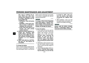
To remove the panelRemove the bolt, and then pull the pan-
el off as shown.To install the panel
Place the panel in the original position,
and then install the bolt.
EAU19642
Checking the spark plugs The spark plugs are important engine
components, which should be checked
periodically, preferably by a Yamaha
dealer. Since heat and deposits will
cause any spark plug to slowly erode,
they should be removed and checked
in accordance with the periodic mainte-
nance and lubrication chart. In addition,
the condition of the spark plugs can re-
veal the condition of the engine.
The porcelain insulator around the cen-
ter electrode of each spark plug should
be a medium-to-light tan (the ideal color
when the vehicle is ridden normally),
and all spark plugs installed in the en-
gine should have the same color. If any
spark plug shows a distinctly different
color, the engine could be operating im-
properly. Do not attempt to diagnose
such problems yourself. Instead, have
a Yamaha dealer check the vehicle.
If a spark plug shows signs of electrode
erosion and excessive carbon or other
deposits, it should be replaced.
1. Panel A
1
1. Bolt
1
Specified spark plug:
NGK/CPR7EA-9
U26PE2E0.book Page 8 Thursday, May 13, 2010 5:38 PM
Page 50 of 86

PERIODIC MAINTENANCE AND ADJUSTMENT
6-9
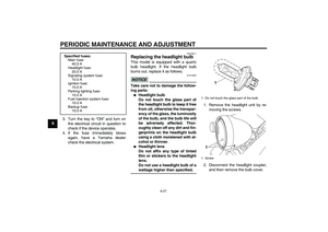
6Before installing a spark plug, the spark
plug gap should be measured with a
wire thickness gauge and, if necessary,
adjusted to specification.
Clean the surface of the spark plug
gasket and its mating surface, and then
wipe off any grime from the spark plug
threads.
TIPIf a torque wrench is not available when
installing a spark plug, a good estimate
of the correct torque is 1/4–1/2 turn
past finger tight. However, the spark
plug should be tightened to the speci-
fied torque as soon as possible.
EAU47112
Engine oil and oil filter car-
tridge The engine oil level should be checked
before each ride. In addition, the oil
must be changed and the oil filter car-
tridge replaced at the intervals speci-
fied in the periodic maintenance and
lubrication chart.
To check the engine oil level
1. Place the vehicle on a level sur-
face and hold it in an upright posi-
tion. A slight tilt to the side can
result in a false reading.
2. Start the engine, warm it up for
several minutes, and then turn it
off.
3. Wait a few minutes until the oil set-
tles.
4. Remove the engine oil filler cap,
wipe the engine oil dipstick clean,
insert it back into the oil filler hole
(without screwing it in), and then
remove it again to check the oil lev-
el.
1. Spark plug gapSpark plug gap:
0.8–0.9 mm (0.031–0.035 in)
Tightening torque:
Spark plug:
13 Nm (1.3 m·kgf, 9.4 ft·lbf)
U26PE2E0.book Page 9 Thursday, May 13, 2010 5:38 PM
Page 51 of 86

PERIODIC MAINTENANCE AND ADJUSTMENT
6-10
6
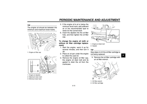
TIPThe engine oil should be between the
minimum and maximum level marks.
5. If the engine oil is at or below the
minimum level mark, add sufficient
oil of the recommended type to
raise it to the correct level.
6. Insert the dipstick into the oil filler
hole, and then tighten the oil filler
cap.
To change the engine oil (with or
without oil filter cartridge replace-
ment)
1. Start the engine, warm it up for
several minutes, and then turn it
off.
2. Place an oil pan under the engine
to collect the used oil.
3. Remove the engine oil filler cap,
the engine oil drain bolt and its
gasket to drain the oil from the
crankcase.
TIPSkip steps 4–6 if the oil filter cartridge is
not being replaced.4. Remove the oil filter cartridge with
an oil filter wrench.
1. Engine oil filler cap
1. Engine oil dipstick
2. Maximum level mark
3. Minimum level mark
1
1
3
2
1. Engine oil drain bolt
2. Gasket
1. Oil filter wrench
2. Oil filter cartridge
1
2
1 2
U26PE2E0.book Page 10 Thursday, May 13, 2010 5:38 PM
Page 52 of 86

PERIODIC MAINTENANCE AND ADJUSTMENT
6-11
6
TIPAn oil filter wrench is available at a
Yamaha dealer.5. Apply a thin coat of clean engine
oil to the O-ring of the new oil filter
cartridge.TIPMake sure that the O-ring is properly
seated.6. Install the new oil filter cartridge
with an oil filter wrench, and then
tighten it to the specified torque
with a torque wrench.7. Install the engine oil drain bolt and
its new gasket, and then tighten
the bolt to the specified torque.
8. Refill with the specified amount of
the recommended engine oil, and
then install and tighten the oil filler
cap.
TIPBe sure to wipe off spilled oil on any
parts after the engine and exhaust sys-
tem have cooled down.NOTICE
ECA11620
�
In order to prevent clutch slip-
page (since the engine oil also
lubricates the clutch), do not
mix any chemical additives. Do
not use oils with a diesel speci-
fication of “CD” or oils of a high-
er quality than specified. In
addition, do not use oils labeled
“ENERGY CONSERVING II” or
higher.
�
Make sure that no foreign mate-
rial enters the crankcase.
1. O-ring
1. Torque wrench
2. Oil filter cartridgeTightening torque:
Oil filter cartridge:
17 Nm (1.7 m·kgf, 12 ft·lbf)
Tightening torque:
Engine oil drain bolt:
43 Nm (4.3 m·kgf, 31 ft·lbf)
1
2
Recommended engine oil:
See page 8-1.
Oil quantity:
Without oil filter cartridge replace-
ment:
3.70 L (3.91 US qt, 3.26 Imp.qt)
With oil filter cartridge replacement:
4.00 L (4.23 US qt, 3.52 Imp.qt)
U26PE2E0.book Page 11 Thursday, May 13, 2010 5:38 PM
Page 53 of 86

PERIODIC MAINTENANCE AND ADJUSTMENT
6-12
6 9. Start the engine, and then let it idle
for several minutes while checking
it for oil leakage. If oil is leaking, im-
mediately turn the engine off and
check for the cause.
TIPAfter the engine is started, the engine
oil level warning light should go off if the
oil level is sufficient.NOTICE
ECA10401
If the oil level warning light flickers
or remains on even if the oil level is
correct, immediately turn the engine
off and have a Yamaha dealer check
the vehicle.10. Turn the engine off, wait a few min-
utes until the oil settles, and then
check the oil level and correct it if
necessary.
EAU47080
Replacing the air filter element The air filter element should be re-
placed at the intervals specified in the
periodic maintenance and lubrication
chart. Replace the air filter element
more frequently if you are riding in un-
usually wet or dusty areas.
To replace the air filter element
1. Remove the air filter case cover by
removing the bolts.
2. Pull the air filter element out.3. Insert a new air filter element into
the air filter case. NOTICE: Make
sure that the air filter element is
properly seated in the air filter
case. The engine should never
be operated without the air filter
element installed, otherwise the
piston(s) and/or cylinder(s) may
become excessively worn.
[ECA10481]
4. Install the air filter case cover by in-
stalling the bolts.
1. Bolt
2. Air filter case cover12
1
1. Air filter element
1
U26PE2E0.book Page 12 Thursday, May 13, 2010 5:38 PM
Page 54 of 86
 at the
inner edge of the throttle g")
PERIODIC MAINTENANCE AND ADJUSTMENT
6-13
6
EAU21384
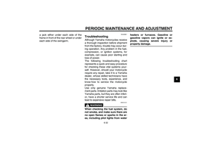
Checking the throttle grip free
play The throttle grip free play should mea-
sure 4.0–6.0 mm (0.16–0.24 in) at the
inner edge of the throttle grip. Periodi-
cally check the throttle grip free play
and, if necessary, have a Yamaha deal-
er adjust it.
EAU21401
Valve clearance The valve clearance changes with use,
resulting in improper air-fuel mixture
and/or engine noise. To prevent this
from occurring, the valve clearance
must be adjusted by a Yamaha dealer
at the intervals specified in the periodic
maintenance and lubrication chart.
EAU21564
Tires To maximize the performance, durabil-
ity, and safe operation of your motorcy-
cle, note the following points regarding
the specified tires.
Tire air pressure
The tire air pressure should be checked
and, if necessary, adjusted before each
ride.
WARNING
EWA10503
Operation of this vehicle with im-
proper tire pressure may cause se-
vere injury or death from loss of
control.�
The tire air pressure must be
checked and adjusted on cold
tires (i.e., when the temperature
of the tires equals the ambient
temperature).
�
The tire air pressure must be ad-
justed in accordance with the
riding speed and with the total
weight of rider, passenger, car-
go, and accessories approved
for this model.
1. Throttle grip free play
1
U26PE2E0.book Page 13 Thursday, May 13, 2010 5:38 PM
Page 55 of 86

PERIODIC MAINTENANCE AND ADJUSTMENT
6-14
6
WARNING
EWA10511
Never overload your vehicle. Opera-
tion of an overloaded vehicle could
cause an accident.
Tire inspection
The tires must be checked before each
ride. If the center tread depth reaches
the specified limit, if the tire has a nail or
glass fragments in it, or if the sidewall is
cracked, have a Yamaha dealer re-
place the tire immediately.TIPThe tire tread depth limits may differ
from country to country. Always comply
with the local regulations.
Tire information
This motorcycle is equipped with cast
wheels and tubeless tires.
WARNING
EWA10461
The front and rear tires should be of
the same make and design, other-
wise the handling characteristics of
the vehicle may be different, which
could lead to an accident.After extensive tests, only the tires list-
ed below have been approved for this
model by Yamaha Motor Co., Ltd.
Tire air pressure (measured on cold
tires):
0–90 kg (0–198 lb):
Front:
225 kPa (2.25 kgf/cm², 33 psi)
Rear:
250 kPa (2.50 kgf/cm², 36 psi)
90–210 kg (198–463 lb):
Front:
225 kPa (2.25 kgf/cm², 33 psi)
Rear:
250 kPa (2.50 kgf/cm², 36 psi)
Maximum load*:
210 kg (463 lb)
* Total weight of rider, passenger, car-
go and accessories
1. Tire sidewall
2. Tire tread depth
Minimum tire tread depth (front and
rear):
1.6 mm (0.06 in)
Front tire:
Size:
130/70-18M/C 63H
Manufacturer/model:
BRIDGESTONE/EXEDRA G721
J
DUNLOP/D404F
Rear tire:
Size:
170/70B16M/C 75H
Manufacturer/model:
BRIDGESTONE/EXEDRA G722
J
DUNLOP/K555
U26PE2E0.book Page 14 Thursday, May 13, 2010 5:38 PM
Page 56 of 86

PERIODIC MAINTENANCE AND ADJUSTMENT
6-15
6
WARNING
EWA10471
�
Have a Yamaha dealer replace
excessively worn tires. Besides
being illegal, operating the vehi-
cle with excessively worn tires
decreases riding stability and
can lead to loss of control.
�
The replacement of all wheel
and brake-related parts, includ-
ing the tires, should be left to a
Yamaha dealer, who has the
necessary professional knowl-
edge and experience to do so.
�
Ride at moderate speeds after
changing a tire since the tire
surface must first be “broken
in” for it to develop its optimal
characteristics.
EAU21961
Cast wheels To maximize the performance, durabil-
ity, and safe operation of your vehicle,
note the following points regarding the
specified wheels.�
The wheel rims should be checked
for cracks, bends or warpage be-
fore each ride. If any damage is
found, have a Yamaha dealer re-
place the wheel. Do not attempt
even the smallest repair to the
wheel. A deformed or cracked
wheel must be replaced.
�
The wheel should be balanced
whenever either the tire or wheel
has been changed or replaced. An
unbalanced wheel can result in
poor performance, adverse han-
dling characteristics, and a short-
ened tire life.
EAU50270
Adjusting the clutch lever free
play The clutch lever free play should mea-
sure 5.0–10.0 mm (0.20–0.39 in) as
shown. Periodically check the clutch le-
ver free play and, if necessary, adjust it
as follows.
1. Slide the rubber cover back at the
clutch lever.
2. Loosen the locknut.
3. To increase the clutch lever free
play, turn the clutch lever free play
adjusting bolt in direction (a). To1. Rubber cover
2. Clutch lever free play adjusting bolt
3. Locknut
4. Clutch lever free play
21
3
4
(a)
(b)
U26PE2E0.book Page 15 Thursday, May 13, 2010 5:38 PM