Page 25 of 86

INSTRUMENT AND CONTROL FUNCTIONS
3-10
3
EAU42535
“RESET” switch
This switch is used to reset the tripme-
ters, to set the clock and to set the
brightness control mode of the multi-
function meter unit.
See “Multi-function meter unit” on page
3-5 for detailed information.
EAU12820
Clutch lever The clutch lever is located at the left
handlebar grip. To disengage the
clutch, pull the lever toward the handle-
bar grip. To engage the clutch, release
the lever. The lever should be pulled
rapidly and released slowly for smooth
clutch operation.
The clutch lever is equipped with a
clutch switch, which is part of the igni-
tion circuit cut-off system. (See page
3-18.)
EAU12881
Shift pedal The shift pedal is located on the left
side of the motorcycle and is used in
combination with the clutch lever when
shifting the gears of the 5-speed con-
stant-mesh transmission equipped on
this motorcycle.TIPUse your toes or heel to shift up and
your toes to shift down.
1. Clutch lever
1
1. Shift pedal
2. Neutral position
1
2 3 4 5N12
U26PE2E0.book Page 10 Thursday, May 13, 2010 5:38 PM
Page 26 of 86
INSTRUMENT AND CONTROL FUNCTIONS
3-11
3
EAU12890
Brake lever The brake lever is located at the right
handlebar grip. To apply the front
brake, pull the lever toward the handle-
bar grip.
EAU12941
Brake pedal The brake pedal is on the right side of
the motorcycle. To apply the rear
brake, press down on the brake pedal.
EAU13121
Fuel tank cap To remove the fuel tank cap
Slide the lock cover open, insert the key
into the lock, and then turn it 1/4 turn
clockwise. The lock will be released
and the fuel tank cap can be removed.
To install the fuel tank cap
1. Insert the fuel tank cap into the
tank opening with the key inserted
in the lock and with the“” mark
facing forward.
1. Brake lever
1
1. Brake pedal
1
1. Fuel tank cap lock cover
2.“” mark
3. Lock.
4. Unlock.
123
4
U26PE2E0.book Page 11 Thursday, May 13, 2010 5:38 PM
Page 27 of 86

INSTRUMENT AND CONTROL FUNCTIONS
3-12
3 2. Turn the key counterclockwise to
the original position, remove it, and
then close the lock cover.
TIPThe fuel tank cap cannot be installed
unless the key is in the lock. In addition,
the key cannot be removed if the cap is
not properly installed and locked.
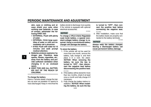
WARNING
EWA10131
Make sure that the fuel tank cap is
properly installed before riding.
Leaking fuel is a fire hazard.
EAU13221
Fuel Make sure there is sufficient gasoline in
the tank.
WARNING
EWA10881
Gasoline and gasoline vapors are
extremely flammable. To avoid fires
and explosions and to reduce the
risk of injury when refueling, follow
these instructions.1. Before refueling, turn off the en-
gine and be sure that no one is sit-
ting on the vehicle. Never refuel
while smoking, or while in the vi-
cinity of sparks, open flames, or
other sources of ignition such as
the pilot lights of water heaters and
clothes dryers.
2. Do not overfill the fuel tank. When
refueling, be sure to insert the
pump nozzle into the fuel tank filler
hole. Stop filling when the fuel
reaches the bottom of the filler
tube. Because fuel expands when
it heats up, heat from the engine or
the sun can cause fuel to spill out
of the fuel tank.3. Wipe up any spilled fuel immedi-
ately. NOTICE: Immediately wipe
off spilled fuel with a clean, dry,
soft cloth, since fuel may deteri-
orate painted surfaces or plastic
parts.
[ECA10071]
4. Be sure to securely close the fuel
tank cap.
WARNING
EWA15151
Gasoline is poisonous and can
cause injury or death. Handle gaso-
line with care. Never siphon gaso-
line by mouth. If you should swallow
some gasoline or inhale a lot of gas-
oline vapor, or get some gasoline in
your eyes, see your doctor immedi-1. Fuel tank filler tube
2. Maximum fuel level
1 2
U26PE2E0.book Page 12 Thursday, May 13, 2010 5:38 PM
Page 28 of 86

INSTRUMENT AND CONTROL FUNCTIONS
3-13
3ately. If gasoline spills on your skin,
wash with soap and water. If gaso-
line spills on your clothing, change
your clothes.
EAU33501
NOTICE
ECA11400
Use only unleaded gasoline. The use
of leaded gasoline will cause severe
damage to internal engine parts,
such as the valves and piston rings,
as well as to the exhaust system.Your Yamaha engine has been de-
signed to use regular unleaded gaso-
line with a research octane number of
91 or higher. If knocking (or pinging) oc-
curs, use a gasoline of a different brandor premium unleaded fuel. Use of un-
leaded fuel will extend spark plug life
and reduce maintenance costs.
EAU39451
Fuel tank breather/overflow
hose Before operating the motorcycle:�
Check the fuel tank breather/over-
flow hose connection.
�
Check the fuel tank breather/over-
flow hose for cracks or damage,
and replace it if damaged.
�
Make sure that the end of the fuel
tank breather/overflow hose is not
blocked, and clean it if necessary.
Recommended fuel:
REGULAR UNLEADED GASO-
LINE ONLY
Fuel tank capacity:
17.0 L (4.49 US gal, 3.74 Imp.gal)
Fuel reserve amount (when the fuel
level warning light comes on):
3.4 L (0.90 US gal, 0.75 Imp.gal)
1. Fuel tank breather/overflow hose
1
U26PE2E0.book Page 13 Thursday, May 13, 2010 5:38 PM
Page 29 of 86

INSTRUMENT AND CONTROL FUNCTIONS
3-14
3
EAU13433
Catalytic converter This model is equipped with a catalytic
converter in the exhaust system.
WARNING
EWA10862
The exhaust system is hot after op-
eration. To prevent a fire hazard or
burns:�
Do not park the vehicle near
possible fire hazards such as
grass or other materials that
easily burn.
�
Park the vehicle in a place
where pedestrians or children
are not likely to touch the hot
exhaust system.
�
Make sure that the exhaust sys-
tem has cooled down before do-
ing any maintenance work.
�
Do not allow the engine to idle
more than a few minutes. Long
idling can cause a build-up of
heat.
NOTICE
ECA10701
Use only unleaded gasoline. The use
of leaded gasoline will cause unre-
pairable damage to the catalytic
converter.
EAU42750
Rider seat To remove the rider seat
1. Insert the key into the seat lock,
and then turn it counterclockwise.
2. Lift the front of the seat up, and
then pull the seat off.
To install the rider seat
1. Insert the projection on the rear of
the seat into the seat holder as
shown.1. Rider seat lock
2. Unlock.
2
1
U26PE2E0.book Page 14 Thursday, May 13, 2010 5:38 PM
Page 30 of 86
INSTRUMENT AND CONTROL FUNCTIONS
3-15
3
2. Push the front of the seat down to
lock it in place.
3. Remove the key.
TIPMake sure that the seat is properly se-
cured before riding.
EAU14322
Helmet holder The helmet holder is located under the
rider seat.
To secure a helmet to the helmet
holder
1. Remove the rider seat. (See page
3-14.)
2. Hook the helmet onto the helmet
holder, and then securely install
the seat. WARNING! Never ride
with a helmet attached to the
helmet holder, since the helmet
may hit objects, causing loss of
control and possibly an acci-
dent.
[EWA10161]
To release the helmet from the hel-
met holder
Remove the rider seat, remove the hel-
met from the helmet holder, and then
install the seat.
1. Projection
2. Seat holder
1
2
1. Helmet holder
1
U26PE2E0.book Page 15 Thursday, May 13, 2010 5:38 PM
Page 31 of 86

INSTRUMENT AND CONTROL FUNCTIONS
3-16
3
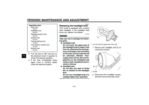
EAU48380
Adjusting the shock absorber
assembly This shock absorber assembly is
equipped with a spring preload adjust-
ing ring, allowing the spring preload to
be adjusted to suit the rider’s prefer-
ence.�
When making this adjustment, use
the special wrench and extension
bar included in the additional tool
kit, which was handed out sepa-
rately at the purchase of the vehi-
cle.
NOTICE
ECA10101
To avoid damaging the mechanism,
do not attempt to turn beyond the
maximum or minimum settings.Adjust the spring preload as follows.
1. Remove panel A. (See page 6-8.)
2. To increase the spring preload and
thereby harden the suspension,
turn the adjusting ring in direction
(a). To decrease the spring pre-
load and thereby soften the sus-
pension, turn the adjusting ring in
direction (b).TIPAlign the appropriate notch in the ad-
justing ring with the position indicator
on the shock absorber.
3. Install the panel.
WARNING
EWA10221
This shock absorber assembly con-
tains highly pressurized nitrogen
gas. Read and understand the fol-
lowing information before handling
the shock absorber assembly.
1. Panel A
2. Spring preload adjusting ring
1
2
1. Special wrench
2. Extension bar
3. Position indicator
Spring preload setting:
Minimum (soft):
1
Standard:
4
Maximum (hard):
9123456789
1
(a)(b)2
3
U26PE2E0.book Page 16 Thursday, May 13, 2010 5:38 PM
Page 32 of 86

INSTRUMENT AND CONTROL FUNCTIONS
3-17
3
�
Do not tamper with or attempt to
open the cylinder assembly.
�
Do not subject the shock ab-
sorber assembly to an open
flame or other high heat source.
This may cause the unit to ex-
plode due to excessive gas
pressure.
�
Do not deform or damage the
cylinder in any way. Cylinder
damage will result in poor
damping performance.
�
Do not dispose of a damaged or
worn-out shock absorber as-
sembly yourself. Take the shock
absorber assembly to a Yamaha
dealer for any service.
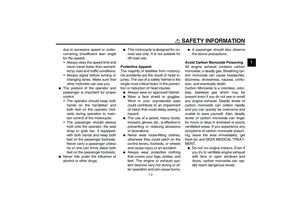
EAU15304
Sidestand The sidestand is located on the left side
of the frame. Raise the sidestand or
lower it with your foot while holding the
vehicle upright.TIPThe built-in sidestand switch is part of
the ignition circuit cut-off system, which
cuts the ignition in certain situations.
(See page 3-18 for an explanation of
the ignition circuit cut-off system.)
WARNING
EWA10241
The vehicle must not be ridden with
the sidestand down, or if the side-
stand cannot be properly moved up
(or does not stay up), otherwise the
sidestand could contact the ground
and distract the operator, resulting
in a possible loss of control.
Yamaha’s ignition circuit cut-off
system has been designed to assist
the operator in fulfilling the respon-
sibility of raising the sidestand be-
fore starting off. Therefore, checkthis system regularly and have a
Yamaha dealer repair it if it does not
function properly.
U26PE2E0.book Page 17 Thursday, May 13, 2010 5:38 PM