Page 269 of 458

7-6Starting and operating
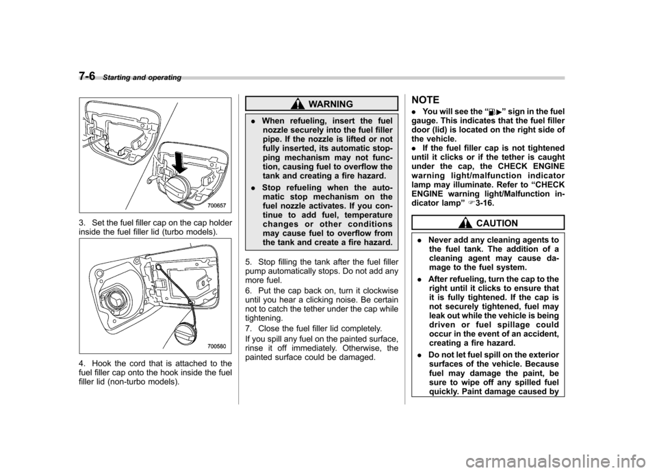
3. Set the fuel filler cap on the cap holder
inside the fuel filler lid (turbo models).
4. Hook the cord that is attached to the
fuel filler cap onto the hook inside the fuel
filler lid (non-turbo models).
WARNING
. When refueling, insert the fuel
nozzle securely into the fuel filler
pipe. If the nozzle is lifted or not
fully inserted, its automatic stop-
ping mechanism may not func-
tion, causing fuel to overflow the
tank and creating a fire hazard.
. Stop refueling when the auto-
matic stop mechanism on the
fuel nozzle activates. If you con-
tinue to add fuel, temperature
changes or other conditions
may cause fuel to overflow from
the tank and create a fire hazard.
5. Stop filling the tank after the fuel filler
pump automatically stops. Do not add any
more fuel.
6. Put the cap back on, turn it clockwise
until you hear a clicking noise. Be certain
not to catch the tether under the cap whiletightening.
7. Close the fuel filler lid completely.
If you spill any fuel on the painted surface,
rinse it off immediately. Otherwise, the
painted surface could be damaged. NOTE .
You will see the “”sign in the fuel
gauge. This indicates that the fuel filler
door (lid) is located on the right side of
the vehicle.. If the fuel filler cap is not tightened
until it clicks or if the tether is caught
under the cap, the CHECK ENGINE
warning light/malfunction indicator
lamp may illuminate. Refer to “CHECK
ENGINE warning light/Malfunction in-
dicator lamp ”F 3-16.
CAUTION
. Never add any cleaning agents to
the fuel tank. The addition of a
cleaning agent may cause da-
mage to the fuel system.
. After refueling, turn the cap to the
right until it clicks to ensure that
it is fully tightened. If the cap is
not securely tightened, fuel may
leak out while the vehicle is being
driven or fuel spillage could
occur in the event of an accident,
creating a fire hazard.
. Do not let fuel spill on the exterior
surfaces of the vehicle. Because
fuel may damage the paint, be
sure to wipe off any spilled fuel
quickly. Paint damage caused by
Page 334 of 458
5. Take out the jack, jack handle and
wheel nut wrench.
The tools and the spare tire are stored
under the floor of the trunk (4-door) or the
cargo area (5-door). Refer to“Mainte-
nance tools ”F 9-4.
NOTE
Make sure that the jack is well lubri-
cated before using it.
4-door models with standard spare tire
Others
6. Take out the tool bucket and turn the
attaching bolt counterclockwise, then take
the spare tire out. NOTE
If the spare tire provided in your vehicle
is a temporary spare tire, carefully read“ Temporary spare tire ”F9-2 and
strictly follow the instructions.1) Notch
2) Valve hole
7. If your vehicle has wheel covers, insert
a flat-head screwdriver into the notch on
the opposite side of the valve hole and pry
the wheel cover to remove it.
In case of emergency 9-7
– CONTINUED –
Page 336 of 458

12. Before putting the spare tire on, clean
the mounting surface of the wheel and hub
with a cloth.
13. Put on the spare tire. Replace the
wheel nuts. Tighten them by hand.
WARNING
Do not use oil or grease on the
wheel studs or nuts when the spare
tire is installed. This could cause the
nuts to become loose and lead to anaccident.
14. Turn the jack handle counterclockwise
to lower the vehicle.
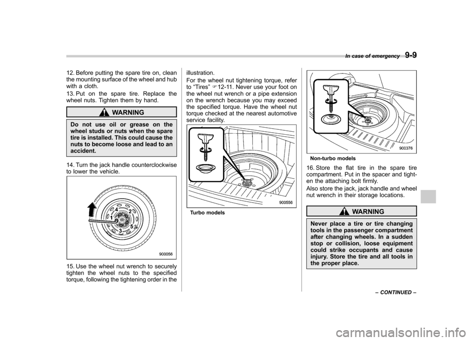
15. Use the wheel nut wrench to securely
tighten the wheel nuts to the specified
torque, following the tightening order in the illustration.
For the wheel nut tightening torque, refer to
“Tires ”F 12-11. Never use your foot on
the wheel nut wrench or a pipe extension
on the wrench because you may exceed
the specified torque. Have the wheel nut
torque checked at the nearest automotive
service facility.
Turbo models
Non-turbo models
16. Store the flat tire in the spare tire
compartment. Put in the spacer and tight-
en the attaching bolt firmly.
Also store the jack, jack handle and wheel
nut wrench in their storage locations.
WARNING
Never place a tire or tire changing
tools in the passenger compartment
after changing wheels. In a sudden
stop or collision, loose equipment
could strike occupants and cause
injury. Store the tire and all tools in
the proper place. In case of emergency
9-9
– CONTINUED –
Page 340 of 458

Engine overheating
WARNING
Never attempt to remove the radia-
tor cap until the engine has been
shut off and has fully cooled down.
When the engine is hot, the coolant
is under pressure. Removing the
cap while the engine is still hot
could release a spray of boiling hot
coolant, which could burn you very
seriously.
If the engine overheats, safely pull off the
road and stop the vehicle in a safe place. & If steam is coming from the
engine compartment
Turn off the engine and get everyone
away from the vehicle until it cools down. & If no steam is coming from
the engine compartment
NOTE
For details about how to check the
coolant level or how to add coolant,
refer to “Engine coolant ”F 11-14.
1. Keep the engine running at idlingspeed. 2. Open the hood to ventilate the engine
compartment. Refer to
“Engine hood ”
F 11-5.
Confirm that the cooling fan is turning. If
the fan is not turning, immediately turn off
the engine and contact your authorized
dealer for repair.
3. After the engine coolant temperature
has dropped, turn off the engine.
If any of the following conditions occur,
turn off the engine. .The temperature gauge stays in the
overheated zone (turbo models). Referto “Temperature gauge (turbo models) ”
F 3-11.
. The coolant temperature high warn-
ing light remains illuminated (non-
turbo models). Refer to “Coolant tem-
perature low indicator light (non-turbo
models)/Coolant temperature high
warning light (non-turbo models) ”F 3-
17.
4. After the engine has fully cooled down,
check the coolant level in the reservetank.
If the coolant level is below the “LOW ”
mark, add coolant up to the “FULL ”mark.
5. If there is no coolant in the reserve
tank, add coolant to the reserve tank.
Then remove the radiator cap and fill the
radiator with coolant. If you remove the radiator cap from a hot
radiator, first wrap a thick cloth around the
radiator cap, then turn the cap counter-
clockwise slowly without pressing down
until it stops. Release the pressure from
the radiator. After the pressure has been
fully released, remove the cap by pressing
down and turning it.
In case of emergency
9-13
Page 347 of 458
9-20In case of emergency
clockwise.
To close the moonroof, turn the wrench counterclockwise.
Have your vehicle checked and repaired
by an authorized SUBARU dealer.
Page 395 of 458
11-42Maintenance and service
& Rear window wiper blade assembly
1. Raise the wiper arm off the rear
window.
2. Turn the wiper blade assembly coun- terclockwise.
3. Pull the wiper blade assembly toward
you to remove it from the wiper arm.
4. Install the wiper blade assembly to the
wiper arm. Make sure that it locks in place.
5. Hold the wiper arm by hand and slowly
lower it in position. &
Rear window wiper blade rubber
1. Pull out the end of the blade rubber
assembly to unlock it from the plasticsupport.
Page 401 of 458
11-48Maintenance and service
Left-hand side
2. Use a screwdriver to remove the
secured clip of the washer tank. To make
it easy to access the bulb, move the
washer tank to the horizontal direction
(left-hand side).3. Remove the bulb cover, by turning it counterclockwise.
4. Disconnect the electrical connector
from the bulb.
5. Remove the bulb from the headlight
assembly by turning it counterclockwise.
6. Replace the bulb with a new one. At
this time, do not touch the bulb surface.
7. To install the bulb to the headlight
assembly, turn it clockwise until it clicks.
8. Reconnect the electrical connector.
9. Install the bulb cover.
10. Install the air intake duct with clips
(right-hand side).
11. Set the washer tank to the original
place and secure it by clip (left-hand side).
Page 402 of 458
!High beam light bulbs
Right-hand side
1. Use a screwdriver to undo the clips on
the air intake duct, then remove the air
intake duct (right-hand side).
Left-hand side 2. Use a screwdriver to remove the
secured clip of the washer tank. To make
it easy to access the bulb, move the
washer tank to the horizontal direction
(left-hand side).
3. Disconnect the electrical connector
from the bulb.
4. Remove the bulb from the headlight
assembly by turning it counterclockwise.
5. Replace the bulb with new one. At this
time, use care not to touch the bulbsurface.
6. To install the bulb to the headlight
assembly, turn it clockwise until it clicks.
7. Reconnect the electrical connector.
8. Install the air intake duct with clips
(right-hand side).
9. Set the washer tank to the original
place and secure it by clip (left-hand side).
Maintenance and service
11-49
– CONTINUED –