2011 SUBARU IMPREZA WRX clock
[x] Cancel search: clockPage 114 of 458
Trunk lid (4-door)
WARNING
. To prevent dangerous exhaust
gas from entering the vehicle,
always keep the trunk lid closed
while driving.
. Help prevent children, adults or
animals from locking themselves
in the trunk. On hot or sunny
days, the temperature in the
trunk could quickly become high
enough to cause death or serious
heat-related injuries including
brain damage to anyone locked
inside, particularly for small chil-dren.
. When leaving the vehicle, either
close all windows and lock all
doors. Also make certain that the
trunk is closed. &
To open and close the trunk
lid from outside
The trunk lid can be opened using the
remote keyless entry system. Refer to“ Remote keyless entry system ”F 2-8.
To close the trunk lid, lightly press the
trunk lid down until the latch engages.
NOTE
Do not leave your valuables in the
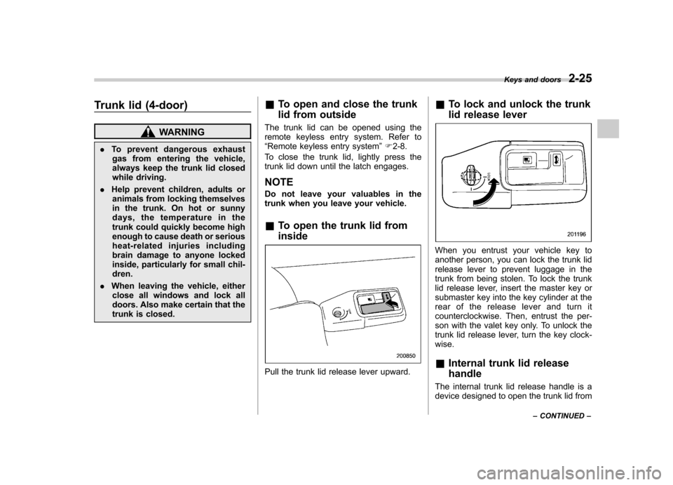
trunk when you leave your vehicle. & To open the trunk lid from inside
Pull the trunk lid release lever upward. &
To lock and unlock the trunk
lid release lever
When you entrust your vehicle key to
another person, you can lock the trunk lid
release lever to prevent luggage in the
trunk from being stolen. To lock the trunk
lid release lever, insert the master key or
submaster key into the key cylinder at the
rear of the release lever and turn it
counterclockwise. Then, entrust the per-
son with the valet key only. To unlock the
trunk lid release lever, turn the key clock-wise. &Internal trunk lid release handle
The internal trunk lid release handle is a
device designed to open the trunk lid from Keys and doors
2-25
– CONTINUED –
Page 121 of 458
Instruments and controlsCruise control set indicator light ......................... 3-27
Front fog light indicator light (if equipped) .......... 3-27
Headlight indicator light (if equipped) ................. 3-27
Driver ’s control center differential auto indicator
light (STI) ......................................................... 3-27
Driver ’s control center differential indicator and
warning lights (STI) .......................................... 3-27
REV indicator light (STI) ..................................... 3-28
Clock ................................................................... 3-28
Information display ............................................ 3-29
Outside temperature indicator ............................ 3-29
Current fuel consumption (if equipped) ............... 3-30
Average fuel consumption .................................. 3-30
Turn off display of fuel consumption indicator .......................................................... 3-31
Light control switch ........................................... 3-31
Headlights. ......................................................... 3-32
High/low beam change (dimmer) ......................... 3-32
Headlight flasher ................................................ 3-32 Daytime running light system
............................. 3-33
Turn signal lever ................................................ 3-33
Illumination brightness control ......................... 3-33
Headlight beam leveler (if equipped) ............... 3-34
Front fog light switch (if equipped) .................. 3-36
Wiper and washer .............................................. 3-36
Windshield wiper and washer switches .............. 3-38
Rear window wiper and washer switch –
5-door ............................................................. 3-39
Mirrors ................................................................ 3-40
Inside mirror ...................................................... 3-40
Auto-dimming mirror/compass (if equipped) ....... 3-40
Auto-dimming mirror/compass with HomeLink
®(if equipped) .................................................... 3-41
Outside mirrors ................................................. 3-47
Defogger and deicer .......................................... 3-48
Tilt/telescopic steering wheel ........................... 3-50
Horn .................................................................... 3-51
Page 135 of 458

3-16Instruments and controls
.Continuous illumination of the
warning light
. Illumination of the warning light
while driving
& Front passenger ’s frontal
airbag ON and OFF indica- tors
ON /: Front passenger ’s frontal airbag ON
indicator
/: Front passenger ’s frontal airbag OFF
indicator
The front passenger ’s frontal airbag ON
and OFF indicators show you the status of
the front passenger ’s SRS frontal airbag.
The indicators are located next to the
clock in the center portion of the dash- board.
When the ignition switch is turned to the “
ON ”position, both the ON and OFF
indicators illuminate for 6 seconds during
which time the system is checked. Follow-
ing the system check, both indicators turn
off for 2 seconds. After that, one of the
indicators illuminates depending on the
status of the front passenger ’s SRS frontal
airbag determined by the SUBARU ad-
vanced frontal airbag system monitoring.
If the front passenger ’s SRS frontal airbag
is activated, the passenger ’s frontal airbag
ON indicator will illuminate while the OFF
indicator will remain off.
If the front passenger ’s SRS frontal airbag
is deactivated, the passenger ’sfrontal
airbag ON indicator will remain off while
the OFF indicator will illuminate.
With the ignition switch turned to the “ON ”
position, if both the ON and OFF indica-
tors remain illuminated or off simulta-
neously even after the system check
period, the system is malfunctioning.
Contact your SUBARU dealer immedi-
ately for an inspection. &
CHECK ENGINE warn-
ing light/Malfunction in-
dicator lamp
CAUTION
If the CHECK ENGINE light illumi-
nates while you are driving, have
your vehicle checked/repaired by
your SUBARU dealer as soon as
possible. Continued vehicle opera-
tion without having the emission
control system checked and re-
paired as necessary could cause
serious damage, which may not be
covered by your vehicle ’s warranty.
If this light illuminates steadily or blinks
while the engine is running, it may indicate
that there is a problem or potential
problem somewhere in the emission con-
trol system. ! If the light illuminates steadily
If the light illuminates steadily while driving
or does not turn off after the engine starts,
an emission control system malfunction
has been detected.
You should have your vehicle checked by
an authorized SUBARU dealer immedi-
ately.
Page 147 of 458
3-28Instruments and controls
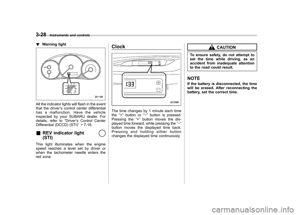
!Warning light
All the indicator lights will flash in the event
that the driver ’s control center differential
has a malfunction. Have the vehicle
inspected by your SUBARU dealer. For
details, refer to “Driver ’s Control Center
Differential (DCCD) (STI) ”F 7-18.
& REV indicator light (STI)
This light illuminates when the engine
speed reaches a level set by driver or
when the tachometer needle enters the
red zone. Clock
The time changes by 1 minute each time the
“+ ” button or “� ” button is pressed.
Pressing the “+ ” button moves the dis-
played time forward, while pressing the “� ”
button moves the displayed time back.
Pressing and holding either button
changes the displayed time continuously.
CAUTION
To ensure safety, do not attempt to
set the time while driving, as an
accident from inadequate attention
to the road could result.
NOTE
If the battery is disconnected, the time
will be erased. After reconnecting the
battery, set the correct time.
Page 150 of 458
corresponding to that trip meter indica-
tion is not shown until the vehicle has
subsequently covered a distance of 1
mile (or 1 km). &Turn off display of fuel con-
sumption indicator
The display of the fuel consumption
indicator can be turned off.
To turn off the display of the indicator, turn
the ignition switch to the “LOCK ”position
and press the “+ ” button adjacent to the
information display for approximately 5
seconds. Then, the information display
and the clock display will blink for 3
seconds to notify that the display of the
fuel consumption has been turned off.
To restore the indicator, once again pressthe “+ ” button for approximately 5 sec-
onds. NOTE . The initial display setting of the fuel
consumption indicator of your vehicle
has been set to operational at the time
of shipment from the factory. . The average fuel consumption is
calculated even while the indicator is
not displayed.. Even if you turn off the fuel con-
sumption indicator, the fuel consump-
tion indicator will automatically turn on when the battery voltage is discon-
nected and then reconnected for bat-
tery replacement or fuse replacement.
Light control switch
The light control switch operates when the
key is inserted into the ignition switch.
Regardless of the position of the light
control switch, the illuminated lights are
turned off when the key is removed from
the ignition switch. NOTE
Even if the key is removed from the
ignition switch, the lights can be illu-
minated by operating the light control
switch from
“OFF ”to the “
”or “”
position. In this case, if the driver ’s
door is opened, a chirp sound will
inform the driver that the lights are illuminated.
CAUTION
. Use of any lights for a long period
of time while the engine is not
running can cause the battery todischarge.
. Before leaving the vehicle, make
sure that the light control switch
is turned to the “OFF ”position. If
the vehicle is left unattended for
a long time with the light control
switch set to a position otherthan “OFF ”, the battery may be
Instruments and controls
3-31
– CONTINUED –
Page 152 of 458
&Daytime running light system
WARNING
The brightness of the illumination of
the high beam headlights is reduced
by the daytime running light system.
The light switch must always be
turned to the “
”position when it
is dark outside.
The high beam headlights will automati-
cally illuminate at reduced brightness
when the engine has started, under the
following conditions: . The select lever is in a position other
than the “P ”position (AT models).
. The parking brake is fully released.
. The light switch is in the “OFF ”or “
”
position.
NOTE
When the light switch is in the “
”
position, the front side marker lights,
tail lights and license plate lights areilluminated. Turn signal lever
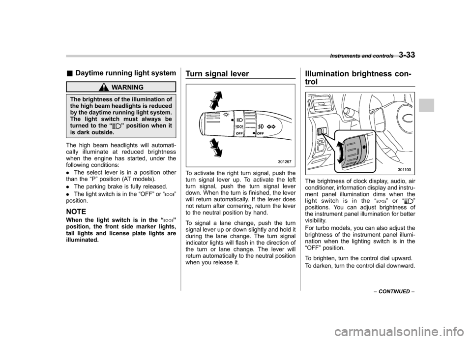
To activate the right turn signal, push the
turn signal lever up. To activate the left
turn signal, push the turn signal lever
down. When the turn is finished, the lever
will return automatically. If the lever does
not return after cornering, return the lever
to the neutral position by hand.
To signal a lane change, push the turn
signal lever up or down slightly and hold it
during the lane change. The turn signal
indicator lights will flash in the direction of
the turn or lane change. The lever will
return automatically to the neutral position
when you release it.Illumination brightness con- trol
The brightness of clock display, audio, air
conditioner, information display and instru-
ment panel illumination dims when the
light switch is in the
“
”or “”
positions. You can adjust brightness of
the instrument panel illumination for better
visibility.
For turbo models, you can also adjust the
brightness of the instrument panel illumi-
nation when the lighting switch is in the“ OFF ”position.
To brighten, turn the control dial upward.
To darken, turn the control dial downward. Instruments and controls
3-33
– CONTINUED –
Page 158 of 458

!Washer
To wash the windshield, push the washer
button at the end of the wiper control lever.
The washer fluid sprays until you release
the washer button. The wipers operate
while you push the button. &
Rear window wiper and
washer switch –5-door
: Washer (accompanied by wiper operation)
ON: Continuous
INT: Intermittent
OFF: Off
: Washer
! Rear wiper
To turn the rear wiper on, turn the knob on
the end of the wiper control lever upward
to the “INT ”or “ON ”position.
To turn the wiper off, return the knob on
the end of the lever to the “OFF ”position.
Withtheswitchturnedtothe “INT ”
position, the rear wiper will operate inter-
mittently at intervals corresponding to the
vehicle speed (longer when the vehicle
speed is low, shorter when the vehicle speed is high).
When you subsequently move the select
lever to the
“R ”position (AT models) or the
shift lever to the reverse position (MT
models), the rear wiper will switch to
continuous operation. When you move
the select lever/shift lever from the “R ”/
reverse position to some other position,
the rear wiper will return to intermittentoperation. ! Washer
To wash the rear window while the rear
wiper is operating, turn the knob clockwise
to the “
”position. The washer fluid
sprays until you release the knob.
To wash the rear window when the rear
wiper is not in use, turn the knob counter-
clockwise to the “
”position. The washer
fluid sprays, and 2 seconds later the rear
wiper operates. Releasing the knob stops
the washer fluid spray, and 3 seconds
later the rear wiper stops. Instruments and controls
3-39
Page 180 of 458
&Fan speed control dial
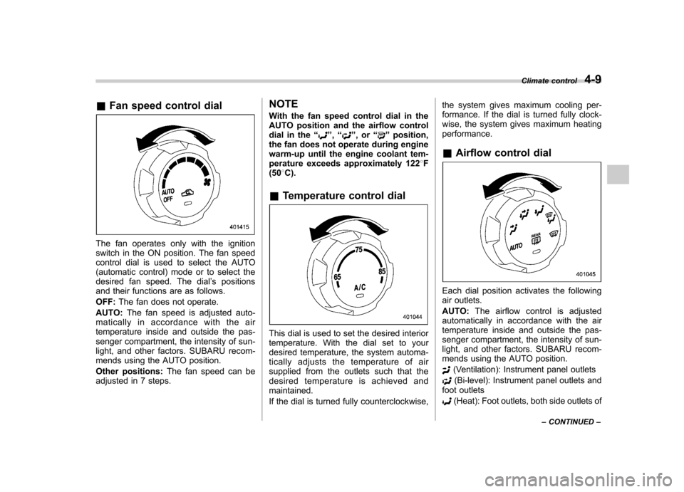
The fan operates only with the ignition
switch in the ON position. The fan speed
control dial is used to select the AUTO
(automatic control) mode or to select the
desired fan speed. The dial ’s positions
and their functions are as follows. OFF: The fan does not operate.
AUTO: The fan speed is adjusted auto-
maticallyinaccordancewiththeair
temperature inside and outside the pas-
senger compartment, the intensity of sun-
light, and other factors. SUBARU recom-
mends using the AUTO position.
Other positions: The fan speed can be
adjusted in 7 steps. NOTE
With the fan speed control dial in the
AUTO position and the airflow control
dial in the
“
”, “”,or “”position,
the fan does not operate during engine
warm-up until the engine coolant tem-
perature exceeds approximately 122 8F
(50 8C).
& Temperature control dial
This dial is used to set the desired interior
temperature. With the dial set to your
desired temperature, the system automa-
tically adjusts the temperature of air
supplied from the outlets such that the
desired temperature is achieved andmaintained.
If the dial is turned fully counterclockwise, the system gives maximum cooling per-
formance. If the dial is turned fully clock-
wise, the system gives maximum heatingperformance. &
Airflow control dial
Each dial position activates the following
air outlets. AUTO: The airflow control is adjusted
automatically in accordance with the air
temperature inside and outside the pas-
senger compartment, the intensity of sun-
light, and other factors. SUBARU recom-
mends using the AUTO position.
(Ventilation): Instrument panel outlets
(Bi-level): Instrument panel outlets and
foot outlets
(Heat): Foot outlets, both side outlets of Climate control
4-9
– CONTINUED –