2011 SUBARU IMPREZA WRX oil type
[x] Cancel search: oil typePage 100 of 458

&Selecting audible signal op- eration
Using an electronic chirp, the system will
give you an audible signal when the doors
lock and unlock. If desired, you may turn
the audible signal off.
Do the following to deactivate the audible
signal. You can also use the same steps
to restore the function.
1. Sit in the driver ’s seat and shut all
doors and the rear gate.
2. Hold down the REAR (UNLOCK) side
of the power door locking switch.
3. While holding down the REAR (UN-
LOCK) side of the power door locking
switch, pull the key out and re-insert it into
the ignition switch at least 6 times within
10 seconds after Step 2.
4. Open and close the driver ’s door once
within 10 seconds after Step 3.
5. The turn signal lights flash 3 times to
indicate completion of the setting.
You may have the above settings done by
your SUBARU dealer. Also, for models
with the genuine SUBARU navigation
system, the setting can be changed using
the navigation monitor. For details, please
refer to the Owner ’s Manual supplement
for the navigation system. &
Replacing the battery
CAUTION
. Do not let dust, oil or water get on
or in the transmitter when repla-
cing the battery.
. Be careful not to damage the
printed circuit board in the trans-
mitter when replacing the battery.
. Be careful not to allow children to
touch the battery and any re-
moved parts; children could
swallow them.
. There is a danger of explosion if
an incorrect replacement battery
is used. Replace only with the
same or equivalent type of bat-
tery.
. Batteries should not be exposed
to excessive heat such as sun-
shine, fire or the like.
When the transmitter battery begins to get
weak, transmitter range will begin to
decrease. Replace the battery as soon
as possible. To replace the battery:
1. Open the transmitter case using a flat-
head screwdriver.
2. Remove the old battery from the
holder.Keys and doors
2-11
– CONTINUED –
Page 276 of 458

not. Remote engine start transmitter pro-
gramming and feature programming can
be adjusted using the following procedure.
1. Open the driver’s door (the driver ’s
door must remain opened throughout the
entire process).
2. Insert the key into the vehicle ’s ignition
switch and turn to the “ON ”position.
3. Locate the small black programming
button behind the fuse box cover, on the
driver ’s side left under the dashboard
panel.
4. Press and hold the black programming
button for 10 to 15 seconds. The horn will
honk and the turn signal lights will flash
three times to indicate that the system has
entered programming mode. At this point
you can proceed to either step 5 or step 6.
5. To program a remote engine start
transmitter: press and release the “
”
button on each transmitter. The horn will
honk and the turn signal lights will flash
one time to indicate a successful trans-
mitter learn each time the “
”button is
pressed. You can program up to eight transmitters.
6. To toggle the Horn Confirmation chirps
ON/OFF: depress and release the brake
pedal to toggle the feature. The horn will
chirp and the turn signal lights will flash
one time to indicate Confirmation Horn
Chirps are “OFF ”. The horn will honk and the turn signal lights will flash 2 times to
indicate Confirmation Horn Chirps are“
ON ”. Depressing the brake pedal repeat-
edly will toggle the feature ON or OFF
each time.
7. To exit the remote engine start trans-
mitter and feature programming mode,
turn the ignition switch to the “LOCK ”
position, remove the key from the ignition
switch and test operation of the remote
engine start transmitter(s) and horn con-
firmation feature.
& System maintenance
! Changing the batteries
CAUTION
. Do not let dust, oil or water get on
or in the remote engine start
transmitter when replacing the
battery.
. Be careful not to damage the
printed circuit board in the re-
mote engine start transmitter
when replacing the battery.
. Be careful not to allow children to
touch the battery and any re-
moved parts; children could
swallow them.
. There is a danger of explosion if an incorrect replacement battery
is used. Replace only with the
same or equivalent type of bat-
tery.
. Batteries should not be exposed
to excessive heat such as sun-
shine, fire or the like.
The two 3-volt lithium batteries (modelCR-1220 ) supplied in your remote engine
start transmitter should last approximately
3 years, depending on usage. When the
batteries begin to weaken, you will notice
a decrease in range (distance from the
vehicle that your remote engine start
system operates). Follow the instructions
below to change the remote engine start
transmitter batteries.
Starting and operating 7-13
– CONTINUED –
Page 366 of 458

&Recommended grade and viscosity
CAUTION
Use only engine oil with the recom-
mended grade and viscosity.
Refer to “Engine oil ”F 12-5.
NOTE
Engine oil viscosity (thickness) affects
fuel economy. Oils of lower viscosity
provide better fuel economy. However,
in hot weather, oil of higher viscosity is
required to properly lubricate the en-gine. & Synthetic oil
You should use synthetic engine oil that
meets the same requirements given for
conventional engine oil. When using
synthetic oil, you must use oil of the same
classification, viscosity and grade shown
in this Owner ’s Manual. Refer to “Engine
oil ”F 12-5. Also, you must follow the oil
and filter changing intervals shown in the
Warranty and Maintenance booklet. NOTE
Synthetic oil of the grade and viscosity
noted in chapter 12 is the required engine oil for optimum engine perfor-
mance. Conventional oil may be used if
synthetic oil is unavailable.
Cooling systemWARNING
Never attempt to remove the radia-
tor cap until the engine has been
shut off and has cooled down
completely. Since the coolant is
under pressure, you may suffer
serious burns from a spray of boil-
ing hot coolant when the cap isremoved.
CAUTION
. Vehicles are filled at the factory
with SUBARU Super Coolant that
does not require the first change
for 11 years/137,500 miles (11
years/220,000 km). This coolant
should not be mixed with any
other brand or type of coolant
during this period. Mixing with a
different coolant will reduce the
life of the coolant. Should it be
necessary to top up the coolant
for any reason, use only
SUBARU Super Coolant.
If the SUBARU Super Coolant is
diluted with another brand or
type, the maintenance interval is Maintenance and service
11-13
– CONTINUED –
Page 373 of 458

11-20Maintenance and service
&Recommended spark plugs
For the recommended spark plugs, refer to “Electrical system ”F 12-3. Drive belts
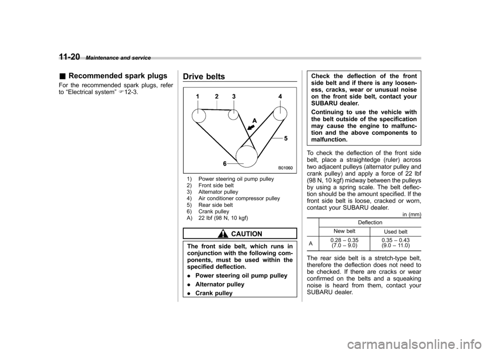
1) Power steering oil pump pulley
2) Front side belt
3) Alternator pulley
4) Air conditioner compressor pulley
5) Rear side belt
6) Crank pulley
A) 22 lbf (98 N, 10 kgf)
CAUTION
The front side belt, which runs in
conjunction with the following com-
ponents, must be used within the
specified deflection. . Power steering oil pump pulley
. Alternator pulley
. Crank pulley Check the deflection of the front
side belt and if there is any loosen-
ess, cracks, wear or unusual noise
on the front side belt, contact your
SUBARU dealer.
Continuing to use the vehicle with
the belt outside of the specification
may cause the engine to malfunc-
tion and the above components tomalfunction.
To check the deflection of the front side
belt, place a straightedge (ruler) across
two adjacent pulleys (alternator pulley and
crank pulley) and apply a force of 22 lbf
(98 N, 10 kgf) midway between the pulleys
by using a spring scale. The belt deflec-
tion should be the amount specified. If the
front side belt is loose, cracked or worn,
contact your SUBARU dealer. in (mm)
Deflection
New belt Used belt
A 0.28
–0.35
(7.0 –9.0) 0.35
–0.43
(9.0 –11.0)
The rear side belt is a stretch-type belt,
therefore the deflection does not need to
be checked. If there are cracks or wear
confirmed on the belts and a squeaking
noise is heard from them, contact your
SUBARU dealer.
Page 455 of 458

14-10Index
Tilt/telescopic ......................................................... 3-50
Stopping the engine ................................................... 7-10
Storage compartment ................................................... 6-4
Sun shade ................................................................ 2-30
Sun visors ................................................................... 6-4
Supplemental Restraint System airbag (SRS) ................ 1-35
Synthetic leather upholstery ........................................ 10-5
T
Tachometer ................................................................. 3-9
Temperature gauge .................................................... 3-11
Temperature warning light AT OIL TEMP ........................................................ 3-18
Coolant ................................................................. 3-17
Rear differential oil ................................................. 3-19
Temporary spare tire .................................................... 9-2
Tether (child restraint system) .............................. 1-29, 1-31
Tie-down hooks ......................................................... 9-14
Tire ............................................................... 11-31, 12-11
Chains .................................................................. 8-11
Inspection ............................................................ 11-33
Pressures and wear .............................................. 11-33
Replacement ........................................................ 11-37
Rotation ............................................................... 11-36
Size and pressure ................................................. 12-11
Types .................................................................. 11-31
Tire pressure monitoring system (TPMS). .... 7-38, 9-10, 11-31
Warning light ......................................................... 3-19
Tires and wheels. ...................................................... 11-31
Tools .......................................................................... 9-4
Top tether anchorages ........................................ 1-29, 1-31 Towing
...................................................................... 9-14
All wheels on the ground ......................................... 9-17
Flat-bed truck ......................................................... 9-17
Hooks ................................................................... 9-14
Trailer Towing .................................................................. 8-15
Trip meter ................................................................... 3-8
Trunk lid .................................................................... 2-25
Release handle ...................................................... 2-25
Trunk light ............................................................... 11-55
Turn signal
Indicator lights ........................................................ 3-26
Lever .................................................................... 3-33
U
Under-floor storage compartment .................................. 6-14
USB storage device operations .................................... 5-37
V
Valet mode ................................................................ 2-19
Vanity mirror ............................................................... 6-4
Vehicle Capacity weight ...................................................... 8-12
Identification ........................................................ 12-19
Symbols .................................................................... 3
Vehicle Dynamics Control
Mode switch .......................................................... 7-36
OFF indicator light .................................................. 3-23
OFF switch ............................................................ 7-37
Operation indicator light ........................................... 3-23
System .................................................................. 7-34