2011 SUBARU IMPREZA ECO mode
[x] Cancel search: ECO modePage 144 of 458
!Traction Control OFF indicator light (green –STI)
The light illuminates when the Vehicle
Dynamics Control mode switch is pressed
briefly. For details, refer to “Traction mode ”
F 7-36.
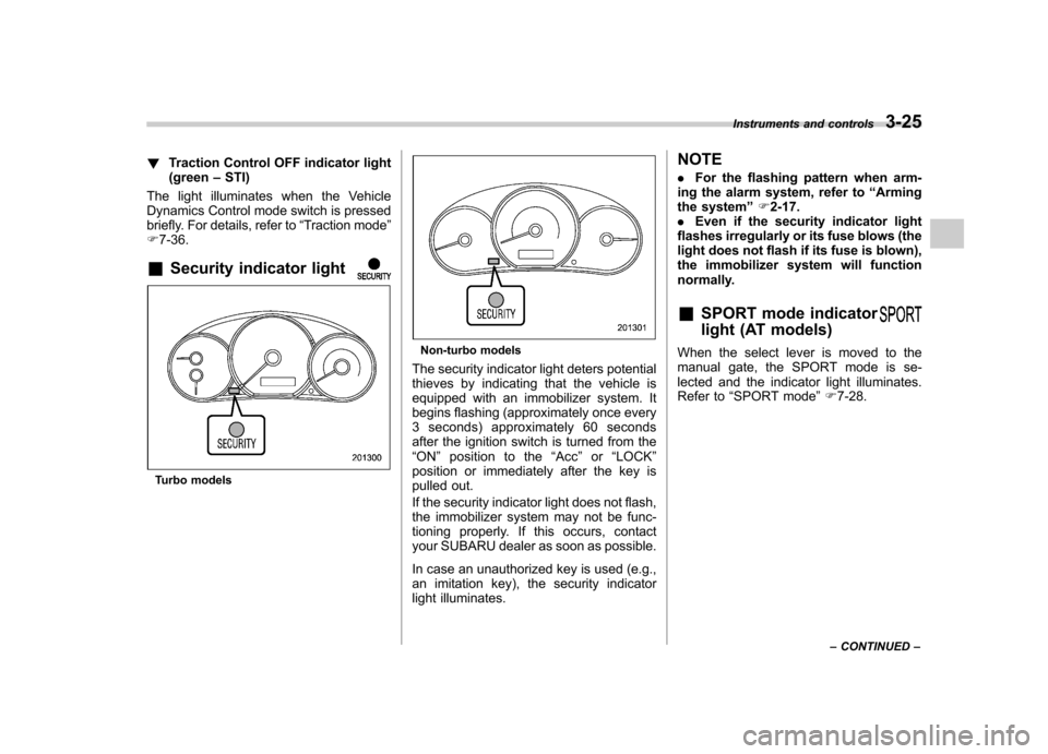
& Security indicator light
Turbo models
Non-turbo models
The security indicator light deters potential
thieves by indicating that the vehicle is
equipped with an immobilizer system. It
begins flashing (approximately once every
3 seconds) approximately 60 seconds
after the ignition switch is turned from the“ ON ”position to the “Acc ”or “LOCK ”
position or immediately after the key is
pulled out.
If the security indicator light does not flash,
the immobilizer system may not be func-
tioning properly. If this occurs, contact
your SUBARU dealer as soon as possible.
In case an unauthorized key is used (e.g.,
an imitation key), the security indicator
light illuminates. NOTE .
For the flashing pattern when arm-
ing the alarm system, refer to “Arming
the system ”F 2-17.
. Even if the security indicator light
flashes irregularly or its fuse blows (the
light does not flash if its fuse is blown),
the immobilizer system will function
normally.
& SPORT mode indicator
light (AT models)When the select lever is moved to the
manual gate, the SPORT mode is se-
lected and the indicator light illuminates.
Refer to “SPORT mode ”F 7-28.
Instruments and controls
3-25
– CONTINUED –
Page 149 of 458
3-30Instruments and controls
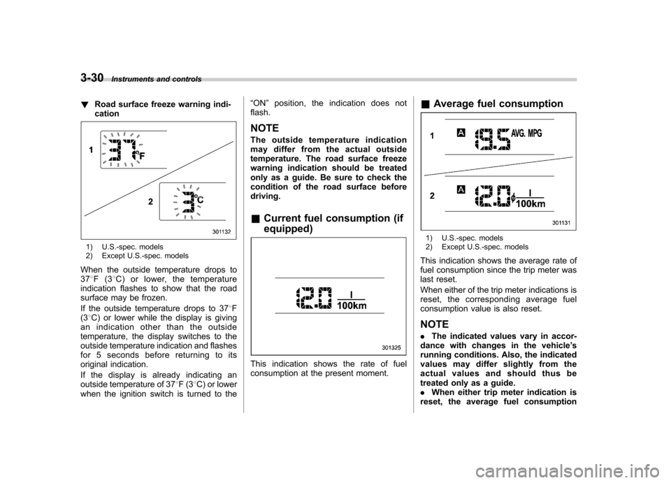
! Road surface freeze warning indi- cation
1) U.S.-spec. models
2) Except U.S.-spec. models
When the outside temperature drops to 37 8F(3 8C) or lower, the temperature
indication flashes to show that the road
surface may be frozen.
If the outside temperature drops to 37 8F
(3 8C) or lower while the display is giving
an indication other than the outside
temperature, the display switches to the
outside temperature indication and flashes
for 5 seconds before returning to its
original indication.
If the display is already indicating an
outside temperature of 37 8F(3 8C) or lower
when the ignition switch is turned to the “
ON ”position, the indication does not
flash. NOTE
The outside temperature indication
may differ from the actual outside
temperature. The road surface freeze
warning indication should be treated
only as a guide. Be sure to check the
condition of the road surface beforedriving. & Current fuel consumption (if equipped)
This indication shows the rate of fuel
consumption at the present moment. &
Average fuel consumption
1) U.S.-spec. models
2) Except U.S.-spec. models
This indication shows the average rate of
fuel consumption since the trip meter was
last reset.
When either of the trip meter indications is
reset, the corresponding average fuel
consumption value is also reset. NOTE . The indicated values vary in accor-
dance with changes in the vehicle ’s
running conditions. Also, the indicated
values may differ slightly from the
actual values and should thus be
treated only as a guide.. When either trip meter indication is
reset, the average fuel consumption
Page 158 of 458

!Washer
To wash the windshield, push the washer
button at the end of the wiper control lever.
The washer fluid sprays until you release
the washer button. The wipers operate
while you push the button. &
Rear window wiper and
washer switch –5-door
: Washer (accompanied by wiper operation)
ON: Continuous
INT: Intermittent
OFF: Off
: Washer
! Rear wiper
To turn the rear wiper on, turn the knob on
the end of the wiper control lever upward
to the “INT ”or “ON ”position.
To turn the wiper off, return the knob on
the end of the lever to the “OFF ”position.
Withtheswitchturnedtothe “INT ”
position, the rear wiper will operate inter-
mittently at intervals corresponding to the
vehicle speed (longer when the vehicle
speed is low, shorter when the vehicle speed is high).
When you subsequently move the select
lever to the
“R ”position (AT models) or the
shift lever to the reverse position (MT
models), the rear wiper will switch to
continuous operation. When you move
the select lever/shift lever from the “R ”/
reverse position to some other position,
the rear wiper will return to intermittentoperation. ! Washer
To wash the rear window while the rear
wiper is operating, turn the knob clockwise
to the “
”position. The washer fluid
sprays until you release the knob.
To wash the rear window when the rear
wiper is not in use, turn the knob counter-
clockwise to the “
”position. The washer
fluid sprays, and 2 seconds later the rear
wiper operates. Releasing the knob stops
the washer fluid spray, and 3 seconds
later the rear wiper stops. Instruments and controls
3-39
Page 160 of 458
other similar items. Periodically wipe the
sensors clean using a piece of dry soft
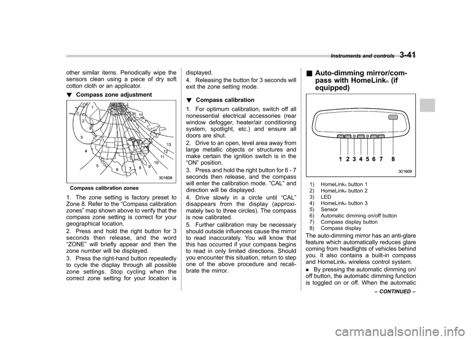
cotton cloth or an applicator. !Compass zone adjustment
Compass calibration zones
1. The zone setting is factory preset to
Zone 8. Refer to the “Compass calibration
zones ”map shown above to verify that the
compass zone setting is correct for your
geographical location.
2. Press and hold the right button for 3
seconds then release, and the word“ ZONE ”will briefly appear and then the
zone number will be displayed.
3. Press the right-hand button repeatedly
to cycle the display through all possible
zone settings. Stop cycling when the
correct zone setting for your location is displayed.
4. Releasing the button for 3 seconds will
exit the zone setting mode. !
Compass calibration
1. For optimum calibration, switch off all
nonessential electrical accessories (rear
window defogger, heater/air conditioning
system, spotlight, etc.) and ensure all
doors are shut.
2. Drive to an open, level area away from
large metallic objects or structures and
make certain the ignition switch is in the“ ON ”position.
3. Press and hold the right button for 6 - 7
seconds then release, and the compass
will enter the calibration mode. “CAL ”and
direction will be displayed.
4. Drive slowly in a circle until “CAL ”
disappears from the display (approxi-
mately two to three circles). The compass
is now calibrated.
5. Further calibration may be necessary
should outside influences cause the mirror
to read inaccurately. You will know that
this has occurred if your compass begins
to read in only limited directions. Should
you encounter this situation, return to step
one of the above procedure and recali-
brate the mirror. &
Auto-dimming mirror/com-
pass with HomeLink
®(if
equipped)
1) HomeLink®button 1
2) HomeLink®button 2
3) LED
4) HomeLink
®button 3
5) Sensor
6) Automatic dimming on/off button
7) Compass display button
8) Compass display
The auto-dimming mirror has an anti-glare
feature which automatically reduces glare
coming from headlights of vehicles behind
you. It also contains a built-in compass
and HomeLink
®wireless control system.
. By pressing the automatic dimming on/
off button, the automatic dimming function
is toggled on or off. When the automatic Instruments and controls
3-41
– CONTINUED –
Page 161 of 458

3-42Instruments and controls
dimming function is on, the LED indicator
will illuminate.
Even with the mirror in the automatic
dimming mode, the mirror surface turns
bright if the transmission is shifted into
reverse. This is to ensure good rearward
visibility during reversing. . By pressing the compass display but-
ton, the compass display is toggled on or
off. When the compass is on, an illumi-
nated compass reading will appear in the
upper right corner of the mirror.
When cleaning the mirror, use a paper
towel or similar material dampened with
glass cleaner. Do not spray glass cleaner
directly on the mirror as that may cause
theliquidcleanertoenterthemirror
housing and damage the mirror. !
Photosensors
The mirror has a photosensor attached on
both the front and back sides. During
nighttime driving, these sensors detect
distracting glare from vehicle headlights
behind you and automatically dim the
mirror to eliminate glare and preserve
your vision. For this reason, use care not
to cover the sensors with stickers, or other
similar items. Periodically wipe the sen-
sors clean using a piece of dry soft cotton
cloth or an applicator. !
Compass zone adjustmentCompass calibration zones
1. Refer to the “Compass calibration
zones ”map shown above to verify that
the compass zone setting is correct for
your geographical location.
2. Press and hold the compass display
button for 3 seconds until the zone
selection comes up (a number will be
displayed in the mirror compass window).
3. Press the compass display button
repeatedly until the correct zone setting
for your location is displayed.
4. Releasing the button for 5 seconds will
exit the zone setting mode.
Page 180 of 458

&Fan speed control dial
The fan operates only with the ignition
switch in the ON position. The fan speed
control dial is used to select the AUTO
(automatic control) mode or to select the
desired fan speed. The dial ’s positions
and their functions are as follows. OFF: The fan does not operate.
AUTO: The fan speed is adjusted auto-
maticallyinaccordancewiththeair
temperature inside and outside the pas-
senger compartment, the intensity of sun-
light, and other factors. SUBARU recom-
mends using the AUTO position.
Other positions: The fan speed can be
adjusted in 7 steps. NOTE
With the fan speed control dial in the
AUTO position and the airflow control
dial in the
“
”, “”,or “”position,
the fan does not operate during engine
warm-up until the engine coolant tem-
perature exceeds approximately 122 8F
(50 8C).
& Temperature control dial
This dial is used to set the desired interior
temperature. With the dial set to your
desired temperature, the system automa-
tically adjusts the temperature of air
supplied from the outlets such that the
desired temperature is achieved andmaintained.
If the dial is turned fully counterclockwise, the system gives maximum cooling per-
formance. If the dial is turned fully clock-
wise, the system gives maximum heatingperformance. &
Airflow control dial
Each dial position activates the following
air outlets. AUTO: The airflow control is adjusted
automatically in accordance with the air
temperature inside and outside the pas-
senger compartment, the intensity of sun-
light, and other factors. SUBARU recom-
mends using the AUTO position.
(Ventilation): Instrument panel outlets
(Bi-level): Instrument panel outlets and
foot outlets
(Heat): Foot outlets, both side outlets of Climate control
4-9
– CONTINUED –
Page 181 of 458
4-10Climate control
the instrument panel and some through
windshield defroster outlets (A small
amount of air flows to the windshield and
both side windows to prevent fogging.)
(Heat-def): Windshield defroster out-
lets, foot outlets and both side outlets of
the instrument panel
: Windshield defroster outlets and both
side outlets of the instrument panel
For details, refer to “Airflow selection ”F 4-
2. NOTE
When the dial is placed in the “
”or
“” position, the air inlet selection is
automatically set to “outside air ”
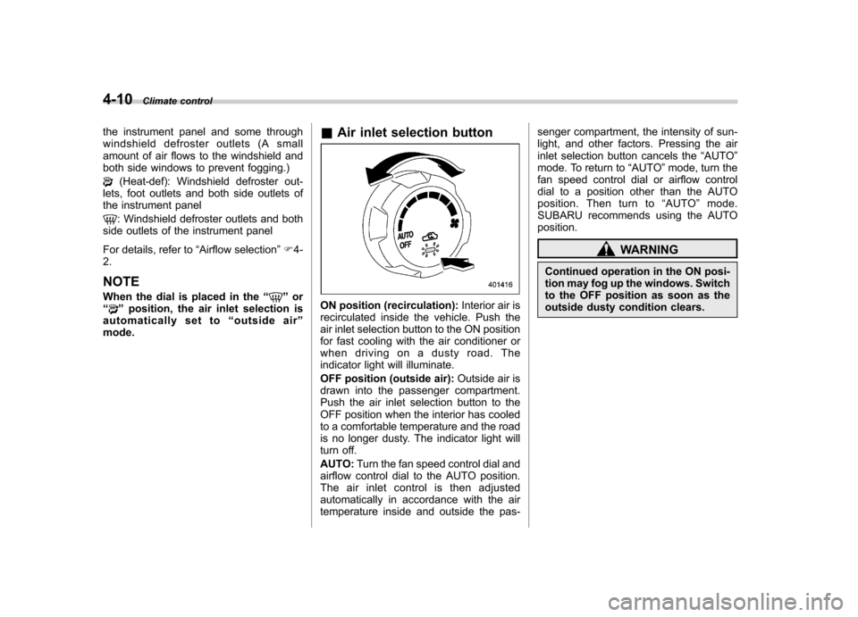
mode. &
Air inlet selection buttonON position (recirculation): Interior air is
recirculated inside the vehicle. Push the
air inlet selection button to the ON position
for fast cooling with the air conditioner or
when driving on a dusty road. The
indicator light will illuminate.
OFF position (outside air): Outside air is
drawn into the passenger compartment.
Push the air inlet selection button to the
OFF position when the interior has cooled
to a comfortable temperature and the road
is no longer dusty. The indicator light will
turn off. AUTO: Turn the fan speed control dial and
airflow control dial to the AUTO position.
The air inlet control is then adjusted
automatically in accordance with the air
temperature inside and outside the pas- senger compartment, the intensity of sun-
light, and other factors. Pressing the air
inlet selection button cancels the
“AUTO ”
mode. To return to “AUTO ”mode, turn the
fan speed control dial or airflow control
dial to a position other than the AUTO
position. Then turn to “AUTO ”mode.
SUBARU recommends using the AUTOposition.
WARNING
Continued operation in the ON posi-
tion may fog up the windows. Switch
to the OFF position as soon as the
outside dusty condition clears.
Page 182 of 458
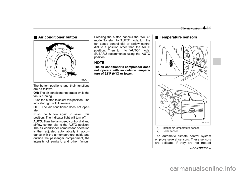
&Air conditioner button
The button positions and their functions
are as follows. ON: The air conditioner operates while the
fan is running.
Push the button to select this position. The
indicator light will illuminate. OFF: The air conditioner does not oper-
ate.
Push the button again to select this
position. The indicator light will turn off. AUTO: Turn the fan speed control dial and
airflow control dial to the AUTO position.
The air conditioner compressor operation
is then adjusted automatically in accor-
dance with the air temperature inside and
outside the passenger compartment, the
intensity of sunlight, and other factors. Pressing the button cancels the
“AUTO ”
mode. To return to “AUTO ”mode, turn the
fan speed control dial or airflow control
dial to a position other than the AUTO
position. Then turn to “AUTO ”mode.
SUBARU recommends using the AUTOposition.
NOTE
The air conditioner ’s compressor does
not operate with an outside tempera-
ture of 32 8F(0 8C) or lower. &
Temperature sensors
1) Interior air temperature sensor
2) Solar sensor
The automatic climate control system
employs several sensors. These sensors
are delicate. If they are not treated Climate control
4-11
– CONTINUED –