2011 Seat Ibiza SC headlight bulb
[x] Cancel search: headlight bulbPage 6 of 278
Accessories, parts replacement and
modifications . . . . . . . . . . . . . . . . . . . . . . . . . . . . . 183
Accessories and spare parts . . . . . . . . . . . . . . . . 183
Technical modifications . . . . . . . . . . . . . . . . . . . . 183
Roof aerial* . . . . . . . . . . . . . . . . . . . . . . . . . . . . . . 184
Mobile telephones and two-way radios . . . . . . . . 184
Fitting a towing bracket* . . . . . . . . . . . . . . . . . . . 185
Checking and refilling levels . . . . . . . . . . . . . . . 187
Refuelling . . . . . . . . . . . . . . . . . . . . . . . . . . . . . . . 187
LPG system* . . . . . . . . . . . . . . . . . . . . . . . . . . . . . 189
Petrol . . . . . . . . . . . . . . . . . . . . . . . . . . . . . . . . . . . 192
Diesel . . . . . . . . . . . . . . . . . . . . . . . . . . . . . . . . . . . 192
Working in the engine compartment . . . . . . . . . . 193
Engine oil . . . . . . . . . . . . . . . . . . . . . . . . . . . . . . . . 196
Coolant . . . . . . . . . . . . . . . . . . . . . . . . . . . . . . . . . 200
Washer fluid and windscreen wiper blades . . . . 202
Brake fluid . . . . . . . . . . . . . . . . . . . . . . . . . . . . . . . 205
Vehicle battery . . . . . . . . . . . . . . . . . . . . . . . . . . . 207
Wheels . . . . . . . . . . . . . . . . . . . . . . . . . . . . . . . . . . 209
If and when . . . . . . . . . . . . . . . . . . . . . . . . . . . . . . . 215
Vehicle tools, spare wheel . . . . . . . . . . . . . . . . . . 215
Wheel change . . . . . . . . . . . . . . . . . . . . . . . . . . . . 216
Tyre repair kit (Tyre-Mobility-System)* . . . . . . . . . 221
Fuses . . . . . . . . . . . . . . . . . . . . . . . . . . . . . . . . . . . 223
Bulb change . . . . . . . . . . . . . . . . . . . . . . . . . . . . . 226
Single headlight bulb change . . . . . . . . . . . . . . . 228
Double headlight bulb change . . . . . . . . . . . . . . . 230
Changing the bulbs of AFS headlights . . . . . . . . 234
Changing the fog light bulbs . . . . . . . . . . . . . . . . 235
Changing the rear, side and interior light bulbs . 237
Jump-starting . . . . . . . . . . . . . . . . . . . . . . . . . . . . . 240
Towing and tow-starting . . . . . . . . . . . . . . . . . . . . 243 Technical Specifications
. . . . . . . . . . . 246
Description of specifications . . . . . . . . . . . . . . . 246
Important information . . . . . . . . . . . . . . . . . . . . . 246
Information on fuel consumption . . . . . . . . . . . . 248
Towing a trailer . . . . . . . . . . . . . . . . . . . . . . . . . . . 248
Wheels . . . . . . . . . . . . . . . . . . . . . . . . . . . . . . . . . . 249
Technical specifications . . . . . . . . . . . . . . . . . . . . 250
Checking fluid levels . . . . . . . . . . . . . . . . . . . . . . . 250
Petrol engine 1.2 44 kW (60 PS) . . . . . . . . . . . . . 251
Petrol engine 1.2 51 kW (70 PS) . . . . . . . . . . . . . 252
Petrol engine/LPG 1.6 60 kW (81 PS) . . . . . . . . . 253
Petrol engine 1.4 63 kW (85 PS) . . . . . . . . . . . . . 254
Petrol engine 1.2 TSI 77 kW (105 PS) . . . . . . . . . 255
Petrol engine 1.2 TSI 77 kW (105 PS) Start-Stop 256
Petrol engine 1.6 77 kW (105 PS) . . . . . . . . . . . . 257
Petrol engine 1.4 110 kW (150 PS) . . . . . . . . . . . 258
Petrol engine 1.4 132 kW (180 PS) - Cupra . . . . . 259
Diesel engine 1.2 TDI CR 55 kW (75 PS) DPF
Start-Stop Ecomotive . . . . . . . . . . . . . . . . . . . . . . 260
Diesel engine 1.2 TDI CR 55 kW (75 PS) DPF . . . . 261
Diesel engine 1.6 TDI CR 66 kW (90 PS) DPF . . . . 262
Diesel engine 1.6 TDI CR 77 kW (105 PS) with/
without DPF . . . . . . . . . . . . . . . . . . . . . . . . . . . . . . 263
Diesel engine 2.0 TDI CR 105 kW (143 PS) DPF . 264
Dimensions and capacities . . . . . . . . . . . . . . . . . 266
Index . . . . . . . . . . . . . . . . . . . . . . . . . . . . . . . . . . . 267
4Table of Contents
Page 69 of 278

67
Cockpit
WARNING
● Always drive according to the road weather conditions, the terrain
and traffic. Driving recommendations should never lead to illegal ma-
noeuvres in surrounding traffic.
● The diesel engine particulate filter may reach extremely high temper-
atures; it should not enter into contact with flammable materials under-
neath the vehicle. Otherwise there is a risk of fire.
Engine oil pressure
If this warning lamp is red it indicates that the engine oil
pressure is too low.
If this warning symbol starts to flash, and is accompanied by three audible
warnings, switch off the engine and check the oil level. If necessary, add
more oil ⇒ page 198.
If the symbol flashes although the oil level is correct, do not drive on. The
engine must not even run at idle speed. Obtain technical assistance.
Checking the oil level
If the warning lamp is yellow the engine oil level should be checked as
soon as possible. Top up the oil ⇒ page 198 at the next opportunity.
Oil level sensor faulty*
If the yellow warning lamp flashes, take the vehicle to a specialised
workshop to have the oil level sensor checked. Until then it is advisable to
check the oil level every time you refuel. Bulb defect*
The indicator lights up when a bulb is not functioning.
The warning lamp lights up when there is a fault on the turn signals,
headlights, side lights and fog lights.
Washer fluid
This warning lamp lights up to indicate that the windscreen
washer level is too low. This serves as a reminder to fill up the reservoir at the earliest opportunity
⇒ page 202
Rear fog light*
This warning lamp lights up when the rear fog light is switched on . For
further information see ⇒ page 94.
Anti-lock brake system (ABS)*
A warning lamp monitors the ABS.
The indicator lamp should light up for a few seconds when the ignition is
switched on. It goes out again after the system has run through an automat-
ic test sequence.
Safety FirstOperating InstructionsPractical TipsTechnical Specifications
Page 98 of 278
96Lights and visibility
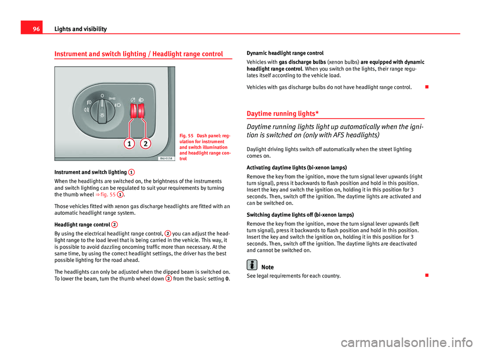
Instrument and switch lighting / Headlight range control
Fig. 55 Dash panel: reg-
ulation for instrument
and switch illumination
and headlight range con-
trol
Instrument and switch lighting 1
When the headlights are switched on, the brightness of the instruments
and switch lighting can be regulated to suit your requirements by turning
the thumb wheel
⇒ fig. 55 1
.
Those vehicles fitted with xenon gas discharge headlights are fitted with an
automatic headlight range system.
Headlight range control 2
By using the electrical headlight range control, 2 you can adjust the head-
light range to the load level that is being carried in the vehicle. This way, it
is possible to avoid dazzling oncoming traffic more than necessary. At the
same time, by using the correct headlight settings, the driver has the best
possible lighting for the road ahead.
The headlights can only be adjusted when the dipped beam is switched on.
To lower the beam, turn the thumb wheel down 2
from the basic setting
0.Dynamic headlight range control
Vehicles with
gas discharge bulbs (xenon bulbs) are equipped with dynamic
headlight range control . When you switch on the lights, their range regu-
lates itself according to the vehicle load.
Vehicles with gas discharge bulbs do not have headlight range control.
Daytime running lights*
Daytime running lights light up automatically when the igni-
tion is switched on (only with AFS headlights)
Daylight driving lights switch off automatically when the street lighting
comes on.
Activating daytime lights (bi-xenon lamps)
Remove the key from the ignition, move the turn signal lever upwards (right
turn signal), press it backwards to flash position and hold in this position.
Insert the key and switch the ignition on, holding it in this position for 3
seconds. Then, switch off the ignition. The daytime lights are activated and
can be switched on.
Switching daytime lights off (bi-xenon lamps)
Remove the key from the ignition, move the turn signal lever upwards (left
turn signal), press it backwards to flash position and hold in this position.
Insert the key and switch the ignition on, holding it in this position for 3
seconds. Then, switch off the ignition. The daytime lights are deactivated
and cannot be switched on.
Note
See legal requirements for each country.
Page 103 of 278
101
Lights and visibility
Note
● The turn signals only work when the ignition is switched on. The corre-
sponding warning lamp or flashes in the instrument panel. The warn-
ing lamp flashes when the turn signals are operated, provided a trailer is
correctly attached and connected to the vehicle. If a turn signal bulb is de-
fective, the warning lamp flashes at double speed. If the trailer turn signal
bulbs are damaged, warning lamp does not light up. Change the bulb.
● The main beam headlights can only be switched on if the dipped beam
headlights are already on. The warning lamp then comes on in the instru-
ment panel.
● The headlight flasher comes on for as long as you pull the lever – even if
no other lights are switched on. The warning lamp then comes on in the
instrument panel.
● When the parking lights are switched on, the headlight and the tail light
on the corresponding side of the vehicle light up. The parking lights will on-
ly work if the key is removed from the ignition. If the lights are switched on,
an acoustic signal will be emitted while the driver door is open.
● If the turn signal lever is left on after the key has been taken out of the
ignition lock, an acoustic signal sounds when the driver door is opened.
This is a reminder to switch off the turn signal, unless of course you wish to
leave the parking light on. Interior lights
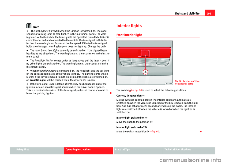
Front interior light
Fig. 60 Interior roof trim:
front interior lights
The switch A
⇒ fig. 60 is used to select the following positions:
Courtesy light position
Sliding switch in central position The interior lights are automatically
switched on when the vehicle is unlocked or the key removed from the igni-
tion. And turn off approx. 20 seconds after closing the doors. The interior
lights are switched off when the vehicle is locked or when the ignition is
switched on.
Interior light switched on
Move the knob to the position .
Interior light switched off O
Move the switch to position O ⇒ fig. 60.
Safety FirstOperating InstructionsPractical TipsTechnical Specifications
Page 228 of 278
226If and when
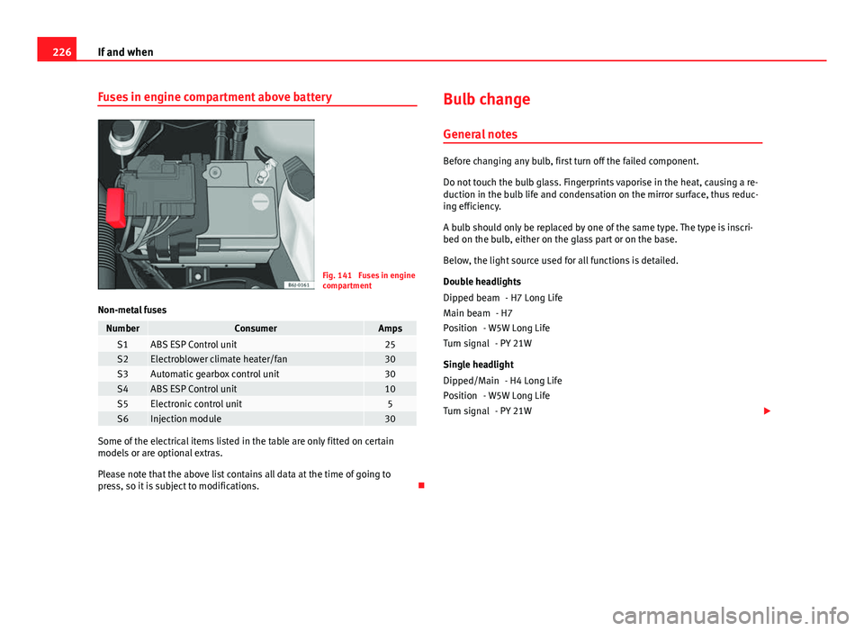
Fuses in engine compartment above battery
Fig. 141 Fuses in engine
compartment
Non-metal fuses
NumberConsumerAmpsS1ABS ESP Control unit25S2Electroblower climate heater/fan30S3Automatic gearbox control unit30S4ABS ESP Control unit10S5Electronic control unit5S6Injection module30
Some of the electrical items listed in the table are only fitted on certain
models or are optional extras.
Please note that the above list contains all data at the time of going to
press, so it is subject to modifications. Bulb change
General notes
Before changing any bulb, first turn off the failed component.
Do not touch the bulb glass. Fingerprints vaporise in the heat, causing a re-
duction in the bulb life and condensation on the mirror surface, thus reduc-
ing efficiency.
A bulb should only be replaced by one of the same type. The type is inscri-
bed on the bulb, either on the glass part or on the base.
Below, the light source used for all functions is detailed.
Double headlights - H7 Long Life
- H7
- W5W Long Life - PY 21W
Single headlight - H4 Long Life
- W5W Long Life - PY 21W
Dipped beam
Main beam
Position
Turn signal
Dipped/Main
Position
Turn signal
Page 229 of 278

227
If and when
Xenon 1)
/adaptive headlights*
- D1S2)
- LED 3)
- LED 3)
- PY 21W
Fog lights - H11
WARNING
● Take particular care when working on components in the engine com-
partment if the engine is warm - risk of burns!
● Bulbs are highly sensitive to pressure. The glass can break when you
touch the bulb, causing injury.
● The high voltage element of gas discharge bulbs* (xenon light) must
be handled correctly. Otherwise, there is a risk of death.
● When changing bulbs, please take care not to injure yourself on sharp
parts in the headlight housing.
CAUTION
● Remove the ignition key before working on the electric system. If not, a
short circuit could occur.
● Switch off the lights or parking lights before you change a bulb.
Dipped and full beam
Position
DRL (day light)
Turn signals
Fog light/cornering
For the sake of the environment
Please ask your specialist retailer how to dispose of used bulbs in the prop-
er manner.
Note
● Depending on weather conditions (cold or wet), the front lights, the fog
lights, the tail lights and the turn signals may be temporarily misted. This
has no influence on the useful life of the lighting system. By switching on
the lights, the area through which the beam of light is projected will quickly
be demisted. However, the edges may continue to be misted.
● Please check at regular intervals that all lighting (especially the exterior
lighting) on your vehicle is functioning properly. This is not only in the inter-
est of your own safety, but also that of all other road users.
● Before changing a bulb, make sure you have the correct new bulb.
● Do not touch the glass part of the bulb with your bare hands, use a cloth
or paper towel instead. Otherwise, the fingerprints left on the glass will va-
porise as a result of the heat generated by the bulb, they will be deposited
on the reflector and will impair its surface.
1)
With these types of headlights, the user can replace the indicator bulb. Replacement of the
dipped/main beam bulb must be done by a Technical Service, given that complex elements
must be removed from the vehicle and the automatic control system that incorporates it
must be reset.
2) The Xenon bulbs discharge 2.5 times the light flux and have an average lifespan of 5 times
more than that of halogen bulbs, this means that, except due to unusual circumstances,
there is no need to change the bulbs for the whole life of the vehicle.
3) In the event that there is a fault in the LEDs, the complete headlight must be replaced.
Safety FirstOperating InstructionsPractical TipsTechnical Specifications
Page 230 of 278
228If and when
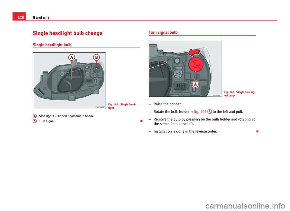
Single headlight bulb change
Single headlight bulb
Fig. 142 Single head-
light
Side lights - Dipped beam/main beam.
Turn signal
A
B
Turn signal bulb
Fig. 143 Single turn sig-
nal lamp
– Raise the bonnet.
– Rotate the bulb holder ⇒ fig. 143 A
to the left and pull.
– Remove the bulb by pressing on the bulb holder and rotating at
the same time to the left.
– Installation is done in the reverse order.
Page 231 of 278

229
If and when
Dipped/main beam headlights
Fig. 144 Dipped beam/
main beam, single head-
light
Fig. 145 Dipped beam/
main beam, single head-
light
– Raise the bonnet.
– Move the loop ⇒ fig. 144 1
in the direction of the arrow and
remove the cover. –
Remove the connector ⇒ fig. 145 2
from the bulb.
– Unclip the retainer spring ⇒ fig. 145 3
pressing inwards to the
right.
– Extract the bulb and fit the replacement so that the rim of the
attachment plate is on the reflector cut-out.
– Fit the connector.
– Fit the cover and close the strap. Make sure that the gasket sits
well on the casing cover during the operation.
– Check whether the new bulb is working.
Side light
Fig. 146 Side lights
– Raise the bonnet.
Safety FirstOperating InstructionsPractical TipsTechnical Specifications