2011 Seat Ibiza SC ECO mode
[x] Cancel search: ECO modePage 2 of 278
SEAT S.A. se preocupa constantemente por mantener todos sus tipos y mode\
los en un desarrollo continuo. Por ello le rogamos que com-
prenda que, en cualquier momento, puedan producirse modificaciones del v\
ehículo entregado en cuanto a la forma, el equipamiento y
la técnica. Por esta razón, no se puede derivar derecho alguno bas\
ándose en los datos, las ilustraciones y descripciones del presente
Manual.
Los textos, las ilustraciones y las normas de este manual se basan en el\
estado de la información en el momento de la realización de la
impresión. Salvo error u omisión, la información recogida en el\
presente manual es válida en la fecha de cierre de su edición.
No está permitida la reimpresión, la reproducción o la traducci\
ón, total o parcial, sin la autorización escrita de SEAT.
SEAT se reserva expresamente todos los derechos según la ley sobre el\
“Copyright”. Reservados todos los derechos sobre modificación.
❀Este papel está fabricado con celulosa blanqueada sin cloro.
© SEAT S.A. - Reimpresión: 15.12.11
Portada IBIZA SC_interior.indd 104/01/12 10:17
Page 56 of 278
54Cockpit
Rev counter
The rev counter displays the engine speed in revolutions per
minute.
The start of the red zone ⇒ fig. 30 1
indicates the maximum engine speed
operating at service temperature. However, it is advisable to change up a in-
to a higher gear, move the selector lever to D or lift your foot off the acceler-
ator before the needle reaches the red zone.
CAUTION
The rev counter needle must never enter the red zone on the scale. Risk of
engine damage.
For the sake of the environment
Changing up into higher gears sooner, following the recommended gear in-
dications ⇒ fig. 33 will help you to reduce fuel consumption, emissions and
also engine noise.
Speedometer
The speedometer is equipped with a digital odometer and a trip recorder, in
addition to a service intervals display.
During the running-in period, the instructions shown on ⇒ page 166
should be followed. LPG system*
LPG gauge
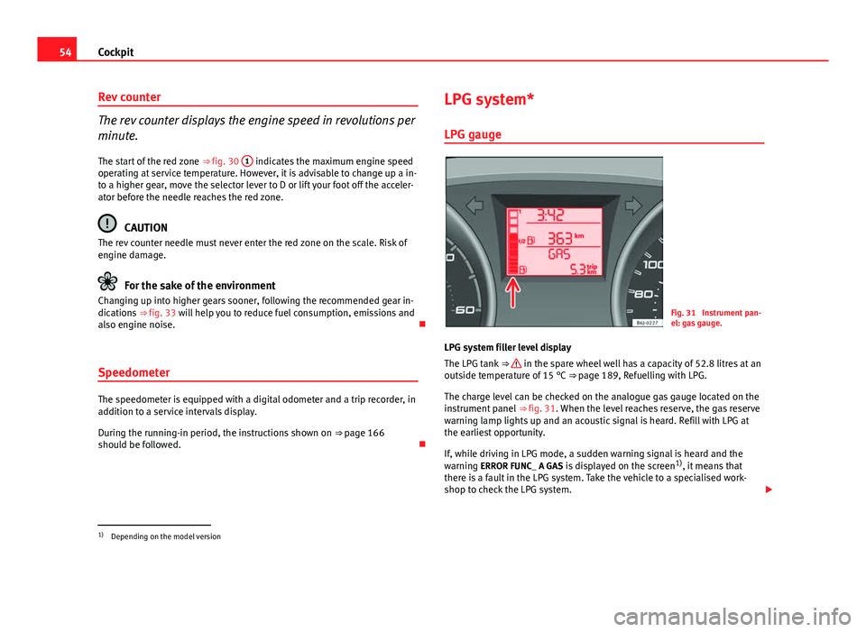
Fig. 31 Instrument pan-
el: gas gauge.
LPG system filler level display
The LPG tank ⇒
in the spare wheel well has a capacity of 52.8 litres at an
outside temperature of 15 °C ⇒ page 189, Refuelling with LPG.
The charge level can be checked on the analogue gas gauge located on the
instrument panel ⇒ fig. 31. When the level reaches reserve, the gas reserve
warning lamp lights up and an acoustic signal is heard. Refill with LPG at
the earliest opportunity.
If, while driving in LPG mode, a sudden warning signal is heard and the
warning ERROR FUNC_ A GAS is displayed on the screen 1)
, it means that
there is a fault in the LPG system. Take the vehicle to a specialised work-
shop to check the LPG system.
1)
Depending on the model version
Page 60 of 278
58Cockpit
Memory displays
● Driving speed
● Journey duration
● Average speed
● Distance
● Distance to empty
● Average fuel consumption
● Current fuel consumption
● Outside temperature display
● Speed warning
Km/h - Driving speed
Driving speed is digitally shown in the display.
min - Journey duration The display shows the amount of time which has elapsed since the ignition
was switched on.
The maximum display value in both memories is 19 hours and 59 minutes.
The memory will automatically be deleted once this value has been
reached.
Ø mph - Average speedThe average speed will be shown after running a distance of approximately
100 metres. Until then dashes will appear in the display. The display will be
updated every 5 seconds while the vehicle is in motion.
km - Distance travelled The display shows the distance travelled since the ignition was switched on. The maximum display value in both memories is 1999 km. The memory will
automatically be deleted once this value has been reached.
Km - Fuel range The fuel range is calculated using the figures for tank content and current
fuel consumption. It shows how far the vehicle can travel using the same
conditions as a reference.
Ø ltr/100km - Average fuel consumption
The average fuel consumption will be shown after having travelled approxi-
mately 100 metres. Until then dashes will appear in the display. The display
will be updated every 5 seconds while the vehicle is in motion. The amount
of fuel used will not be shown.
l/100 km or l/h - Current fuel consumption The display will show the current fuel consumption in litre/km whilst the ve-
hicle is in motion or in litre/hour when the vehicle is in a stationary position
with the engine running.
Using this display you can see how your driving style affects fuel consump-
tion ⇒ page 168.
Outside temperature display
The measurement margin extends from -45 °C to +58 °C. At temperatures
lower than +4 °C, an “ice crystal symbol” is displayed and a “warning”
sounds if the vehicle is moving at more than 10 km/h (ice warning). This
symbol will flash for about 10 seconds and remains lit until the exterior tem-
perature rises above +4 °C or 6 °C if it was already lit.
Set speed indicator
When the required speed has been reached, enter the “Speed warning”
mode menu and press button A
-RESET-. The set speed is memorised. If
the indicated speed is exceeded at any time, a warning message is dis-
played on the screen and a warning signal sounds. 1)
1)Depending on the model version, the message on the screen may vary and may be repre-
sented by flashing of the speed indication or by a speed message.
Page 67 of 278

65
Cockpit
If several priority 1 faults are detected at the same time, the symbols will be
displayed one after the other for about 2 seconds at a time and will contin-
ue until the fault is corrected.
No menus will be shown in the display for the duration of a priority 1 warn-
ing message.
Examples of priority 1 warning messages (red)
● Brake system symbol with the warning message STOP BRAKE FLUID
SERVICE MANUAL or STOP BRAKE FAULT SERVICE MANUAL .
● Coolant symbol with the warning message STOP SEE COOLANT IN-
STRUCTION MANUAL.
● Engine oil pressure symbol with the warning message STOP ENGINE
OIL PRESSURE LOW! INSTRUCTION MANUAL .
Warning reports, Priority 2 (yellow)
If one of these faults occurs, the warning lamp lights up, and is accompa-
nied by one audible warning. Check the corresponding function as soon as
possible although the vehicle may be used without risk.
If several priority 2 warning messages are detected at the same time, the
symbols are displayed one after the other for about 2 seconds at a time. Af-
ter a set time, the information text will disappear and the symbol will be
shown as a reminder at the side of the display.
Priority 2 warning messages will not be shown until all Priority 1 warning
messages have been dealt with!
Examples of priority 2 warning messages (yellow): 1)
● Fuel warning light with the information text PLEASE REFUEL. Information messages displayed on the screen*
Message
a)Description
SERVICEThe service interval has ended. Take the vehicle to an au-
thorised service.
IMMOBILIS-
ERImmobiliser system active. The vehicle will not start. Take
the vehicle to an authorised service.
ERRORInstrument panel faulty. Take the vehicle to an authorised
service.
CLEAN AIRFILTERWarning: Clean the air filter.
NO KEYWarning: Correct key cannot be found in the vehicle.KEY BATTERYWarning: Key battery low. Change the battery.
CLUTCHWarning: Press the clutch to start. In vehicles with manual
gearbox and Start/Stop system.
--> P/NWarning: Place the selector level in P/N to start. Only in ve-
hicles with automatic gearbox.
--> PWarning: Place the selector lever in position P to stop the
engine.
STARTINGWarning: The engine starts automatically. Start-Stop system
activated.
START MAN- UALLYWarning: The engine must be started manually. Start-Stop
system activated.
ERROR
START STOPWarning: Start-Stop system error.
START STOP
IMPOSSIBLEWarning: Although the Start-Stop system is switched on, the
engine cannot be stopped automatically. Not all the neces-
sary conditions are met.
START STOP ACTIVEWarning: Start-Stop system activated. Vehicle in Stop mode.
1)
Depending on the version of the model.
Safety FirstOperating InstructionsPractical TipsTechnical Specifications
Page 72 of 278
70Cockpit
Tyre pressure*
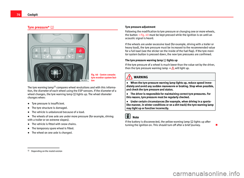
Fig. 40 Centre console:
tyre monitor system but-
ton
The tyre warning lamp 1)
compares wheel revolutions and with this informa-
tion, the diameter of each wheel using the ESP sensors. If the diameter of a
wheel changes, the tyre warning lamp lights up. The wheel diameter
changes when:
● Tyre pressure is insufficient.
● The tyre structure is damaged.
● The vehicle is unbalanced because of a load.
● The wheels of one axle are under more pressure (for example, driving
with a trailer or on extreme slopes).
● The vehicle is fitted with snow chains.
● The temporary spare wheel is fitted.
● The wheel on one axle is changed. Tyre pressure adjustment
Following the modification to tyre pressure or changing one or more wheels,
the button ⇒ fig. 40 must be kept pressed while the ignition is on until an
acoustic signal is heard.
If the wheels are under excessive load (for example, driving with a trailer or
heavy load), the tyre pressure must be increased to the recommended value
for a full load (see the sticker on the inside of the fuel flap). If the tyre moni-
tor system button is pressed down, the new tyre pressures are confirmed.
The tyre pressure warning lamp lights up
If the tyre pressure of a wheel is much lower than the value set by the driver,
then the tyre pressure warning lamp ⇒
will light up.
WARNING
● When the tyre pressure warning lamp lights up, reduce speed imme-
diately and avoid any sudden manoeuvre or braking. Stop when possible,
and check the tyre pressure and status.
● The driver is responsible for maintaining correct tyre pressures. For
this reason, tyre pressure must be regularly checked.
● Under certain circumstances (for example, when driving in a sports-
like manner, in winter conditions or on a dirt track) the tyre warning lamp
may light up or function incorrectly.
Note
If the battery is disconnected, the yellow warning lamp lights up after
turning the ignition on. This should turn off after a brief journey.
1)
Depending on the model version
Page 86 of 278
84Unlocking and locking
Anti-theft alarm system*
Description of anti-theft alarm system*
The anti-theft alarm triggers if unauthorised movements are
detected around the vehicle.
The anti-theft alarm makes it more difficult to break into the vehicle or steal
it. The system will initiate acoustic and optical warning signals when your
vehicle is tried to be forced.
The anti-theft alarm system is automatically connected on locking the vehi-
cle. For this, either rotate the key in the locking position or press button
2 on the radio-frequency remote control*. The system is immediately acti-
vated and the turn signal light located on the driver door will flash along
with the turn signals, indicating that the alarm and the locking security sys-
tem (double lock) have been turned on.
If any of the doors or the bonnet are open, they will not be included in the
protection zones of the vehicle when the alarm is connected. If the door or
the bonnet are subsequently closed, they will be automatically included in
the protection areas of the vehicle and the turn signals will flash according-
ly when the doors close.
● The turn signal light will flash twice on opening and deactivating the
alarm..
● The turn signal light will flash once on closing and activating the alarm.
When does the system trigger an alarm?
The system triggers an alarm if the following unauthorised actions are car-
ried out when the car is locked: ●
Opening of vehicle with mechanical key without switching ignition on
within the next 15 seconds
● Opening a door
● Opening the bonnet
● Opening the tailgate
● Ignition switched on with a non-validated key.
● Movements in the driving compartment (vehicles with a volume sensor)
● Towing of the vehicle 1)
● Tilt angle (tow-away protection) 1)
● Undue manipulation of the alarm
● Battery handling
The acoustic signals sound and the turn signals flash for approx. 30 sec-
onds. This may be repeated up to 10 times depending on the country.
Opening all the doors in manual mode
In vehicles without alarm, when opening the driver door manually all the
doors are opened.
How to switch the alarm off
To deactivate the anti-theft alarm, turn the key to the opening direction,
open the door and switch the ignition on, or press the unlocking button
on the remote control.
In vehicles equipped with an anti-theft alarm system, you have 15 seconds
to insert the key in the ignition lock and activate the ignition if the vehicle is
opened using the driver door key.
Otherwise, the alarm will trigger for 30 sec. and the ignition will be blocked.
1)
With vehicles fitted with a tow-away protection
Page 106 of 278
104Lights and visibility
short intervals. Four wiper interval stages can be set using
switch A
.
Slow wipe
– Move the lever up to position 2
.
Continuous wipe
– Move the lever up to position 3
.
Short wipe
– Move the lever down to position 4
to give the windscreen a
short wipe.
Wash and wipe automatic system
– Pull the lever towards the steering wheel - Position 5
, the
windscreen washer is activated.
– Release the lever. The wipers-washers will keep running for ap-
proximately four seconds.
WARNING
● Worn and dirty wiper blades reduce visibility and safety levels while
driving.
● In cold conditions, you should not use the wash / wipe system unless
you have warmed the windscreen with the heating and ventilation sys-
tem. The washer fluid could otherwise freeze on the windscreen and ob-
scure your view of the road.
● Always note the corresponding warnings on ⇒ page 203.
CAUTION
In icy conditions, always check that the wiper blades are not frozen to the
glass before using the wipers for the first time. If you switch on the wipers
when the wiper blades are frozen to the windscreen, you could damage
both the wiper blades and the wiper motor.
Note
● The windscreen wipers will only work when the ignition is switched on.
● The heat output of the heated jets* is controlled automatically when the
ignition is switched on, depending upon the outside temperature.
● In certain versions of vehicles with alarms, the windscreen wiper will on-
ly work in interval/rain sensor mode when the ignition is on and the bonnet
closed.
● When the interval wipe function is on, the intervals are directly propor-
tional to the speed. This way, the higher the vehicle speed the shorter the
intervals.
● If you stop the vehicle with the windscreen wiper in position 1 or 2, it
will automatically change to a lower speed. The set speed will be resumed
when the vehicle pulls away.
Page 108 of 278

106Lights and visibility
–Release the lever. The washer system stops and the wipers con-
tinue until the end of the cycle.
– Move the lever towards the steering wheel to switch off.
WARNING
● Worn and dirty wiper blades reduce visibility and safety levels while
driving.
● Always note the corresponding warnings on ⇒ page 203.
CAUTION
In icy conditions, always check that the wiper blade is not frozen to the
glass before using the wiper for the first time. If you switch on the wiper
when the wiper blade is frozen to the glass, this could damage both the
wiper blade and the wiper motor.
Note
● The rear window wiper will only work when the ignition is switched on.
● Depending on the version of the model, when you engage reverse gear
and with the headlight wiper activated, the lamps are wiped.
Headlight washer*
The headlight washers clean the headlight lenses. The headlight washers are activated automatically when the windscreen
washer is used and the windscreen wiper lever is pulled towards the steer-
ing wheel for at least 1.5 seconds – provided the dipped beam headlights
or main beams are switched on. Clean off stubborn dirt (insects, etc.) from
the headlights at regular intervals, for instance when filling the fuel tank.
Note
● To ensure that the headlight washers work properly in winter, keep the
nozzle holders in the bumper free of snow and remove any ice with a de-icer
spray.
● To remove water, the windscreen wipers will be activated from time to
time, the headlight wipers will be activated every three cycles.
Rear view mirrors
Adjusting the rear view mirrors
Before beginning any journey, adjust the rear view mirrors for correct visibil-
ity.
Interior mirror
It is dangerous to drive if you cannot see clearly through the
rear window. Manual anti-dazzle function for interior mirror
In the basic mirror position, the lever at the bottom edge of the mirror
should be at the front. Pull the lever to the back to select the anti-dazzle
function.