Page 9 of 198

13B-9V4 MR-372-J84-13B000$020.mif
DIESEL INJECTION
Fault finding – System operation13B
DDCR INJECTION
Vdiag No.: 44, 48
Rail pressure check
The quality of combustion is influenced by the size of the atomised droplets in the cylinder. In the combustion
chamber, smaller fuel droplets will have time to burn fully, and will not produce smoke or unburned particles. To
meet the pollution requirements, the droplet size, and therefore the size of the injection holes, must be reduced.
With smaller holes, less fuel will be able to be introduced at a given pressure, which limits the power. To handle this
drawback, the injected fuel flow has to be increased, which means a pressure increase (and more apertures on the
injector nozzles). For the DDCR injection system, the pressure reaches 1400 bar in the rail, and must be constantly
regulated. The measuring circuit consists of an active pressure sensor on the rail connected to an analogue port on
the computer.
The High Pressure pump is supplied at low pressure (5bar) by a built-in transfer pump. This pump supplies the rail.
The rail filling pressure is controlled by the filling valve (IMV) and the discharge pressure is controlled by the injector
valves. This compensates for pressure drops. The filling actuator enables the high pressure pump to supply just
the exact quantity of diesel fuel required to maintain the rail pressure. This mechanism minimises the heat
generated and improves engine output.
In order to discharge the rail using the injector valves, the valves are actuated by short electrical pulses which are:
– short enough not to open the injector (and pass through the return circuit from the injectors),
– long enough to open the valves and discharge the rail.
The fuel surplus is sent back to the fuel filter or the tank, according to its flow. If there is no IMV control, the rail
pressure is limited by a discharge valve fitted on the pump.
Idling speed regulation
The computer handles the calculation of idling speed. This has to take account of the instantaneous power level to
be supplied, according to the following factors:
– Engine coolant temperature
– Gear engaged
– Battery charging
– Electrical consumers (Heating elements, Air conditioning, Fan assembly, Heated windscreen, etc.) active or
inactive
Individual injector correction (C2I)
The DDCR system injectors must be calibrated with corrective values to adjust their flow precisely. Each injector is
calibrated for different pressures on a test bench, and its specifications are shown on a label attached to the body of
the injector holders. These individual correction values are then written to the computer EEPROM, which can then
actuate the injectors by taking into account their manufacturing dispersion.
Page 10 of 198

The angular posit")
13B-10V4 MR-372-J84-13B000$020.mif
DIESEL INJECTION
Fault finding – System operation13B
DDCR INJECTION
Vdiag No.: 44, 48
Measuring the angular position (Cylinder reference sensor)
The angular position is measured using a magneto-inductive sensor triggered by machined teeth on the engine
flywheel. This flywheel has 60 teeth separated by six degrees, minus 2 missing teeth that form a notch.
A second sensor (Hall effect), activated by a machined tooth on the high pressure pump drive pulley
(synchronised with the camshaft), which rotates at half the engine speed, supplies a signal showing the progress of
the injection cycle. By comparing the signals from these two sensors, the computer's APS module (Angular Position
Subsystem) can supply the entire system with the synchronisation factors, namely: the angular position of
the flywheel, the engine speed, the number of the active injector, and the injection cycle timing. This module also
supplies the system with the engine speed signal.
Flow capacity function (VLC)
Because of the combination of several parameters such as the diesel fuel temperature, part wear, clogging of the
diesel filter, etc., the system may reach its limit during its service life. If this happens, the rail pressure cannot be
maintained because the pump lacks the necessary capacity. If the pump lacks the necessary capacity, this
programming will therefore reduce the requested flow to a value that will enable the pressure monitoring system to
control the pressure again.
The customer may have noticed a loss of vehicle performance when this program is activated (confirmed by
ET563 Flow capacity function). This is part of normal operation.
Function: Air flow management.
EGR valve control
The EGR (Exhaust gas recirculation) system comprises a proportional EGR valve with a built-in valve position
feedback potentiometer. The EGR valve position is controlled by the potentiometer in a closed loop and/or by
changes in the estimated air flow.
Calculation of the air flow
WITHOUT FLOWMETER (K9K 722)
Certain models are not fitted with air flowmeters. In this case the amount of fresh inlet air must be evaluated, based
on the values supplied by the surrounding systems. The (theoretical) air volume is calculated using a model with
these calculation parameters:
– the inlet air temperature measured by a sensor located after the turbocharger and/or after the intercooler (if fitted),
– the turbocharging pressure,
– the atmospheric pressure (external air),
– the EGR valve position,
– the fuel flow,
– the engine speed.
The atmospheric pressure sensor is optional. If fitted, it sends back an atmospheric pressure signal to an analogue
port on the micro-controller. If not, atmospheric pressure is recovered based on the turbocharger pressure
and the engine field.
Page 11 of 198

The flow of fresh air entering the engine is given b")
13B-11V4 MR-372-J84-13B000$020.mif
DIESEL INJECTION
Fault finding – System operation13B
DDCR INJECTION
Vdiag No.: 44, 48
WITH FLOWMETER (K9K 728)
The flow of fresh air entering the engine is given by a hot wire ratiometric sensor. This flow sensor is used to
manage the amount of exhaust gas to be recirculated to ensure optimum recirculation rates. A fresh air temperature
sensor is built into the flowmeter.
Air flow measurement allows closed-loop control via the EGR valve.
Besides electrical faults with the sensor, there is a consistency test between the measured air flow and an estimated
air flow without EGR.
This flow evaluates the amount of fresh inlet air, based on the values supplied by the surrounding systems:
– the inlet air temperature measured by a sensor located after the turbocharger and/or after the intercooler (if fitted),
– the turbocharging pressure,
– the engine speed.
Pre-postheating actuation
Pre-postheating actuation consists of controlling the heater plugs and preheating warning light on the instrument
panel. The heater plugs are activated by relays, and the power is supplied from the battery. After the ignition is
switched on. Preheating is activated for a period of time. The warning light is illuminated for an activation period that
depends on the battery voltage, the atmospheric pressure, and the coolant temperature. When the temperature is
below a certain threshold, a postheating function can be used to improve the combustion stability, and consequently
engine operation (reducing unburnt particles and pollutant emissions).
Turbocharger control solenoid valve actuation
The turbocharger system comprises a solenoid valve that is used to actuate the vanes (or wastegate) to create an
overpressure or a vacuum in the inlet circuit.
Page 12 of 198

13B-12V4 MR-372-J84-13B000$020.mif
DIESEL INJECTION
Fault finding – System operation13B
DDCR INJECTION
Vdiag No.: 44, 48
Functions included
Air conditioning management assistance
For vehicles with air conditioning, the DDCR system can switch off the air conditioning under certain engine
operating conditions:
– when requested by the driver,
– when starting the engine,
– if the engine overheats (in order to reduce the power the engine has to supply),
– when the engine speed is kept at a very high level (to protect the compressor),
– during transition phases (e.g. under heavy acceleration when overtaking, anti-stalling and moving off strategies).
These conditions are only taken into account when they do not occur repeatedly, in order to prevent system
instabilities (erratic deactivations),
– when certain faults appear.
Cold loop air conditioning management
The air conditioning is the cold loop type and its management shared between several computers. The injection
computer is responsible for:
– managing demand for cold air according to the passenger compartment commands and the pressure value,
– determining the power absorbed by the compressor from the pressure,
– determining the fan unit commands according to vehicle speed and pressure.
The driver requests the air conditioning to be switched on by means of the ventilation selector coupled to a switch.
The cold air request is authorised or denied depending on the pressure measured. If this pressure is outside
the operating limits, the cold loop program is not activated.
Thermal regulation of the passenger compartment heating circuit
In a direct injection engine, fuel is injected directly into the combustion chamber. This leads to heat being lost
through the upper part of the engine and consequently, the cylinder head cooling circuit is smaller in size.
The effect of this is that the temperature of the coolant flowing through this circuit rises more slowly. However, this
coolant is also used by the passenger compartment heating system. In very cold conditions, it is therefore difficult to
achieve a comfortable passenger compartment temperature quickly.
To limit the time taken to warm up the system, air heating resistors, called RCHs, are fitted into the passenger
compartment heating circuit. The UCH decides whether the RCH are required, the UPC physically actuates
the RCH, and the injection computer determines whether to limit the power supplied to the RCH depending on
alternator charge, and also whether to disable them according to engine speed, load and vehicle speed. NOTE:
Fan unit actuation requests can be made by the injection computer, but these are sent on the CAN. These requests
depend on the air conditioning but also on the coolant temperature and vehicle speed.
Page 13 of 198

13B-13V4 MR-372-J84-13B000$020.mif
DIESEL INJECTION
Fault finding – System operation13B
DDCR INJECTION
Vdiag No.: 44, 48
Cruise control/speed limiter management:
When activated, the cruise control function maintains the vehicle at a preselected speed, regardless of the driving
conditions encountered. Using the control buttons, the driver can increase or decrease the vehicle speed.
The cruise control function can be deactivated either by using the control buttons or by switching off the cruise
control function selection switch, or when system events are detected such as depressing the brake or clutch
pedals, or when system errors are detected such as an inconsistent vehicle speed or excessive vehicle
deceleration. The cruise control function can also be temporarily suspended when the driver wants to resume
control of the vehicle and exceed the selected cruising speed by depressing the accelerator pedal which then
exceeds the selected fuel flow. The cruising speed is resumed when the driver releases the accelerator pedal.
The cruise control function can be reactivated and the last cruising speed can be resumed after deactivating
the function for whatever reason until the vehicle ignition is switched off (i.e. for as long as computer supply not cut
off). The vehicle will then attempt to return to the cruising speed using a controlled vehicle acceleration rate.
When switched on (using the selection switch), the vehicle speed limiter function limits the vehicle speed to a preset
value. The driver controls the vehicle in the normal way using the accelerator pedal until the limit speed is reached.
If an attempt is made to exceed this speed, the system will ignore the pedal request and will control the vehicle
speed as the cruise control function would do, provided that the driver continues to press the accelerator pedal.
As with the cruise control function, the set speed can be altered by adjusting the control buttons, with single touches
or holding down.
For safety reasons, the cruising speed can be exceeded by depressing the accelerator pedal beyond the pedal
position limiting value. Vehicle speed is then controlled using the accelerator pedal until the vehicle speed is
decreased to below the cruising speed, when the limiter function is activated again.
The driver has the following controls for the cruise control/speed limiter function:
– accelerator pedal,
– brake pedal,
– clutch pedal,
– function selector switch, used to select cruise control or speed limiter operating mode.
Instrument panel display
The computer displays certain information on the instrument panel relating to engine operation. This concerns 5
functions: the MIL (Malfunction Indicator Lamp) of the EOBD (European On Board Diagnostic), pre-postheating,
the coolant temperature, and engine faults: Level 1 (non-critical fault) and Level 2 (emergency stop). These five
functions are represented by 3 warning lights or messages displayed by the on-board computer.
Pre-postheating warning light
This light is used both as an in-operation indicator light and as a system fault indicator:
– permanently lit during + after ignition feed: indicates preheating of the heater plugs.
After preheating and an automatic timed 3 second off period, the warning light will come on if a Level 1 fault occurs
(leading to reduced operation and reduced safety levels. The driver should have repairs carried out as soon as
possible.)
Page 14 of 198

13B-14V4 MR-372-J84-13B000$020.mif
DIESEL INJECTION
Fault finding – System operation13B
DDCR INJECTION
Vdiag No.: 44, 48
Temperature / emergency stop warning light
This indicator light is used both as an in-operation indicator light and as a system fault warning light. It illuminates for
3 seconds when the power is switched on (automatic test procedure controlled by the instrument panel)
Continuously lit: indicates engine overheating or a Level 2 fault.
– if the fault reaches a critical level, the injection cuts off automatically after several seconds.
– in the event of engine overheating, it is the driver's choice to stop the car or continue driving.
ACTIVATION PROGRAMMING OF THE INSTRUMENT PANEL WARNING LIGHTS
Orange SERVICE warning light (level 1)
This warning light comes on, accompanied by the faulty injection message.
The driver should have the repairs carried out as soon as possible.
Red STOP warning light (level 2)
This warning light comes on, accompanied by the faulty injection message.
The driver should have the repairs carried out as soon as possible.
Excess pollution OBD ORANGE warning light:
This warning light is used to alert the driver of any injection faults that could lead to excessive pollution, or if
the EOBD system has been deactivated. The injection computer requests illumination of the OBD warning light for
a present fault only after three consecutive driving cycles.
The 3 second visual inspection when the ignition is switched on (automatic test procedure managed by
the instrument panel) is carried out by the injection computer.
Faults that activate the OBD warning light
Associated
faultTitle Specification
DF010 EGR position sensor circuit CC.1 - CO.0
DF016 EGR control circuit CC.1
DF026 Cylinder 1 injector control circuit CO – CC
DF027 Cylinder 2 injector control circuit CO – CC
DF028 Cylinder 3 injector control circuit CO – CC
DF029 Cylinder 4 injector control circuit CO – CC
DF038 Computer 3. DEF
DF114 EGR solenoid valve circuit 4. DEF
Page 15 of 198
13B-15V4 MR-372-J84-13B000$020.mif
DIESEL INJECTION
Fault finding – System operation13B
DDCR INJECTION
Vdiag No.: 44, 48
32-TRACK BLACK CONNECTOR A
Description Tracks Tracks Description
Not used A1 E1 Not used
Cruise control On/Off A2 E2 Not used
CAN L1 A3 E3 Not used
CAN H1 A4 E4 Closed contact Stop signal
Not used B1 F1 Not used
Not used B2 F2 Potentiometer supply Gang 2
Not used B3 F3 Potentiometer signal Gang 2
Diagnostic line K B4 F4 Potentiometer earth Gang 2
Not used C1 G1+After ignition supply
Not used C2 G2 Potentiometer supply Gang 1
Speed limiter on/off C3 G3 Not used
Clutch switch information C4 G4 Earth
+After ignition supply D1 H1 Earth
Cruise control switch signal D2H2 Potentiometer signal Gang 1
Cruise control switch earth D3H3 Potentiometer earth Gang 1
Not used D4 H4 Earth
NOTE:
The supply voltage on track G1 is not measurable when the computer connector is disconnected.
Page 16 of 198

13B-16V4 MR-372-J84-13B000$020.mif
DIESEL INJECTION
Fault finding – System operation13B
DDCR INJECTION
Vdiag No.: 44, 48
48-TRACK BROWN CONNECTOR B
Description Tracks Tracks Description
Flowmeter supply (728, 729) A1 G1 Knock sensor earth (pinking)
Flowmeter signal (728, 729) A2 G2 Fuel temperature signal
Flowmeter earth (728, 729) A3 G3 Fuel temperature sensor earth
Cylinder 1 injector + control A4 G4 Cylinder 4 injector + control
EGR feedback potentiometer supply B1 H1 Not used
EGR feedback potentiometer signal B2 H2 Coolant temperature signal
EGR feedback potentiometer earth B3 H3 Coolant temperature sensor earth
Cylinder 1 injector - control B4 H4 Cylinder 4 injector - control
Turbocharging pressure sensor supply C1 J1 Not used
Turbocharging pressure sensor signal C2 J2 Inlet air temperature signal
Turbocharging pressure sensor earth C3 J3 Inlet air temperature earth (722)
Cylinder 2 injector + control C4 J4 Not used
Rail pressure sensor supply D1 K1 Accelerometer shielding (pinking)
Rail pressure sensor signal D2 K2 External air temperature signal
Rail pressure sensor earth D3 K3 External air temperature earth
Cylinder 2 injector - control D4 K4 Not used
Not used E1 L1 Not used
Phase sensor signal (cylinder) E2 L2 Not used
Phase sensor earth (cylinder) E3 L3 EGR valve control
Cylinder 3 injector + control E4 L4 Not used
Knock sensor signal (pinking) F1 M1 Not used
Engine speed (TDC) sensor + signal F2 M2Turbocharging solenoid valve control
(728, 729)
Engine speed sensor earth (TDC) F3 M3 Not used
Cylinder 3 injector - control F4 M4 Fuel flow actuator control
 1
1 2
2 3
3 4
4 5
5 6
6 7
7 8
8 9
9 10
10 11
11 12
12 13
13 14
14 15
15 16
16 17
17 18
18 19
19 20
20 21
21 22
22 23
23 24
24 25
25 26
26 27
27 28
28 29
29 30
30 31
31 32
32 33
33 34
34 35
35 36
36 37
37 38
38 39
39 40
40 41
41 42
42 43
43 44
44 45
45 46
46 47
47 48
48 49
49 50
50 51
51 52
52 53
53 54
54 55
55 56
56 57
57 58
58 59
59 60
60 61
61 62
62 63
63 64
64 65
65 66
66 67
67 68
68 69
69 70
70 71
71 72
72 73
73 74
74 75
75 76
76 77
77 78
78 79
79 80
80 81
81 82
82 83
83 84
84 85
85 86
86 87
87 88
88 89
89 90
90 91
91 92
92 93
93 94
94 95
95 96
96 97
97 98
98 99
99 100
100 101
101 102
102 103
103 104
104 105
105 106
106 107
107 108
108 109
109 110
110 111
111 112
112 113
113 114
114 115
115 116
116 117
117 118
118 119
119 120
120 121
121 122
122 123
123 124
124 125
125 126
126 127
127 128
128 129
129 130
130 131
131 132
132 133
133 134
134 135
135 136
136 137
137 138
138 139
139 140
140 141
141 142
142 143
143 144
144 145
145 146
146 147
147 148
148 149
149 150
150 151
151 152
152 153
153 154
154 155
155 156
156 157
157 158
158 159
159 160
160 161
161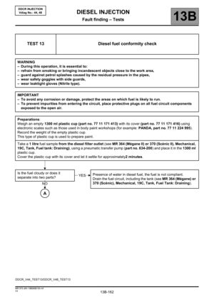 162
162 163
163 164
164 165
165 166
166 167
167 168
168 169
169 170
170 171
171 172
172 173
173 174
174 175
175 176
176 177
177 178
178 179
179 180
180 181
181 182
182 183
183 184
184 185
185 186
186 187
187 188
188 189
189 190
190 191
191 192
192 193
193 194
194 195
195 196
196 197
197