2011 RENAULT SCENIC Air
[x] Cancel search: AirPage 26 of 365

13B-26
MR-372-J84-13B200$180.mif
V13
13B
DIESEL INJECTION
Fault finding – Configuration and programming
Summary of available configuration readings
NOTESConfiguration readings are used to check the status of configurations performed.
The configuration readings cannot be changed.
The computer is configured as soon as the one of the vehicle's optional system
components is operated.
In the event of a fault, consult the interpretation of command RZ005 Programming.
LC009: Heating and air conditioning system
WITH OR WITHOUT
LC056: Heating elements
WITH OR WITHOUT
LC065: Water in diesel fuel sensor
WITH OR WITHOUT
LC120: Cruise control
WITH OR WITHOUT
LC121: Speed limiter
WITH OR WITHOUT
EDC16
Program No: C1
Vdiag No: 18, 1C, 20,
50, 58, 5C
MR-372-J84-13B200$180.mif
Page 28 of 365

13B-28
MR-372-J84-13B200$216.mif
V13
DIESEL INJECTION
Fault finding – Fault summary table
EDC16
Program No: C1
Vdiag No: 18, 1C, 20,
50, 58, 5C
13B
Tool
faultDiagnostic tool titleAssociated
DTCLevel 1 fault
warning light
(Orange
heater plugs
"on" indicator
light)Level 2 fault
warning light
(Red
overheating
warning light)No fault
warning
light onOBD
warning
light lit
DF032Thermoplunger relay 1
control circuit (Vdiag
58, 5C only)1641CO/CC.0/
CC.1/
1.DEF
DF033Thermoplunger relay 2
control circuit (Vdiag
58, 5C only)1642CO/CC.0/
CC.1/
1.DEF
DF034Thermoplunger relay 3
control circuit (Vdiag
58, 5C only)1643CO/CC.0/
CC.1/
1.DEF
DF037Engine immobiliser C167 X
DF038Computer 6066.DEF/8.DEF/
12.DEF1.DEF/2.DEF/
3.DEF/4.DEF/
5.DEF/7.DEF
10.DEF/
11.DEF/
13.DEF/
14.DEF6.DEF
DF039Inlet air temperature
sensor circuit110 CC.0/CO.1
DF040Cylinder 1 injector
circuit201 COCC.1/CC/
1.DEFCO
DF041Cylinder 2 injector
circuit202 COCC.1/CC/
1.DEFCO
DF042Cylinder 3 injector
circuit203 COCC.1/CC/
1.DEFCO
DF043Cylinder 4 injector
circuit204 COCC.1/CC/
1.DEFCO
DF046Battery voltage 5601.DEF/
2.DEF
Page 29 of 365

13B-29
MR-372-J84-13B200$216.mif
V13
DIESEL INJECTION
Fault finding – Fault summary table
EDC16
Program No: C1
Vdiag No: 18, 1C, 20,
50, 58, 5C
13B
Tool
faultDiagnostic tool titleAssociated
DTCLevel 1 fault
warning light
(Orange
heater plugs
"on" indicator
light)Level 2 fault
warning light
(Red
overheating
warning light)No fault
warning
light onOBD
warning
light lit
DF047Computer feed voltage 615 1.DEF
DF049Refrigerant sensor
circuit530 CC.1/CO.0
DF050Brake switch circuit 5711.DEF/
2.DEF
DF051Cruise control/speed
limiter function5751.DEF/
2.DEF/
3.DEF
DF053Rail pressure
regulation function89 3.DEFCC.0/CC.1/CO/
1.DEF/2.DEF/
4.DEF/5.DEF/
6.DEF/7.DEF
DF054Turbocharging
solenoid valve control
circuit33CO/CC.0/CC.1/
1.DEF/
2.DEF/3.DEF
4.DEF/5.DEFCC.0
DF055Turbocharging
pressure regulation
circuit243 1.DEF/2.DEF
DF056Air flow sensor circuit 100CO.0/CC.1/
1.DEF/2.DEFCO.0/
CC.1/
1.DEF/
2.DEF
DF057Water in diesel fuel
detector circuit2264 X
DF058Oil temperature sensor
circuit195CC.0/
CO.1
DF059Misfiring on cylinder 1 301 X
DF060Misfiring on cylinder 2 302 X
Page 33 of 365

13B-33
MR-372-J84-13B200$252.mif
V13
13B
DIESEL INJECTION
Fault finding – Interpretation of faults
DF001
PRESENT
OR
STOREDCOOLANT TEMPERATURE SENSOR CIRCUIT
CC.0: Short circuit to earth
CO.1: Open circuit or short circuit to + 12 V
NOTESConditions for applying the fault finding procedure to stored faults:
The fault is declared present during engine starting attempts or while the engine is
running.
Special notes:
If the fault is present:
– the coolant temperature: PR064 Coolant temperature is fixed at 11 9 ° C,
– the preheating phase is greater than 10 seconds,
– the low speed motor-driven fan assembly (GMV 1) is continuously supplied,
–if fan assembly 1 is faulty, then fan assembly 2 is activated on vehicles equipped
with air conditioning,
– the level 1 warning light is lit,
– the OBD warning light illuminates after three consecutive driving cycles (start the
engine
+ 5 seconds, then switch off the ignition and wait for 1 minute).
Use bornier Elé. 1681 or Elé. 1590 for all operations on the computer connectors.
Check the coolant temperature sensor connections.
Check the injection computer connections.
Repair if necessary.
Measure the resistance of the coolant temperature sensor between connections 3C and 3JK.
Replace the sensor if its resistance is not approximately:
68780 Ω < X < 82780 Ω at - 40°C
12338 Ω < X < 12582 Ω at - 10°C
2140 Ω < X < 2364 Ω at 25°C
772 Ω < X < 850 Ω at 50°C
275 Ω < X < 291 Ω at 80°C
11 2 Ω < X < 118 Ω at 110°C
85 Ω < X < 89 Ω at 120°C
Check the insulation, continuity and the absence of interference resistance on the following connections:
– connection code3C,
– connection code 3JK,
between components 120 and 244.
If the connection or connections are faulty and there is a repair method (see Technical Note 6015A, Repairing
electrical wiring, Wiring: Precautions for repair), repair the wiring, otherwise replace it.
If the fault is still present, replace the coolant temperature sensor.
AFTER REPAIRDeal with any faults.
Carry out a road test followed by another check with the diagnostic tool.
EDC16_V50_DF001/EDC16_V58_DF001/EDC16_V5C_DF001/EDC16_V18_DF001/EDC16_V1C_DF001/EDC16_V20_DF001EDC16
Program No.: C1
Vdiag no.: 18, 1C, 20,
50, 58, 5C
MR-372-J84-13B200$252.mif
Page 34 of 365
13B-34
MR-372-J84-13B200$252.mif
V13
DIESEL INJECTION
Fault finding – Interpretation of faults
EDC16
Program No.: C1
Vdiag no.: 18, 1C, 20,
50, 58, 5C
13B
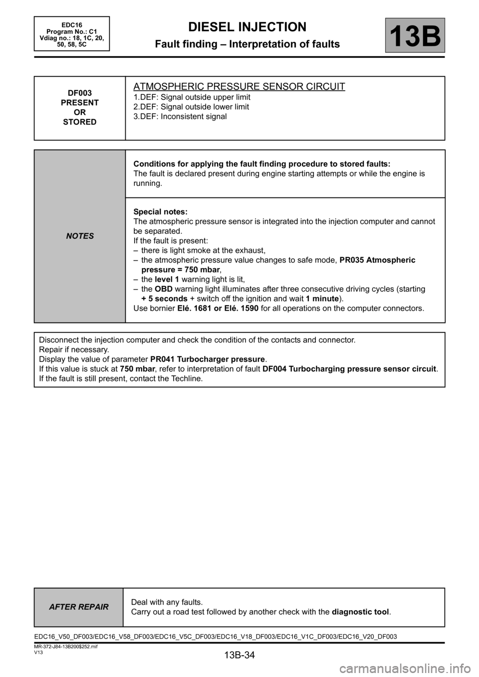
DF003
PRESENT
OR
STOREDATMOSPHERIC PRESSURE SENSOR CIRCUIT
1.DEF: Signal outside upper limit
2.DEF: Signal outside lower limit
3.DEF: Inconsistent signal
NOTESConditions for applying the fault finding procedure to stored faults:
The fault is declared present during engine starting attempts or while the engine is
running.
Special notes:
The atmospheric pressure sensor is integrated into the injection computer and cannot
be separated.
If the fault is present:
– there is light smoke at the exhaust,
– the atmospheric pressure value changes to safe mode, PR035 Atmospheric
pressure = 750 mbar,
– the level 1 warning light is lit,
– the OBD warning light illuminates after three consecutive driving cycles (starting
+ 5 seconds + switch off the ignition and wait 1 minute).
Use bornier Elé. 1681 or Elé. 1590 for all operations on the computer connectors.
Disconnect the injection computer and check the condition of the contacts and connector.
Repair if necessary.
Display the value of parameter PR041 Turbocharger pressure.
If this value is stuck at 750 mbar, refer to interpretation of fault DF004 Turbocharging pressure sensor circuit.
If the fault is still present, contact the Techline.
AFTER REPAIRDeal with any faults.
Carry out a road test followed by another check with the diagnostic tool.
EDC16_V50_DF003/EDC16_V58_DF003/EDC16_V5C_DF003/EDC16_V18_DF003/EDC16_V1C_DF003/EDC16_V20_DF003
Page 35 of 365

13B-35
MR-372-J84-13B200$252.mif
V13
DIESEL INJECTION
Fault finding – Interpretation of faults
EDC16
Program No.: C1
Vdiag no.: 18, 1C, 20,
50, 58, 5C
13B
DF004
PRESENT
OR
STOREDTURBOCHARGING PRESSURE SENSOR CIRCUIT
CO.0: Open circuit or short circuit to earth
CC.1: Short circuit to + 12 V
1.DEF: Inconsistent signal
NOTESConditions for applying the fault finding procedure to stored faults:
The fault is declared present during engine starting attempts or while the engine is
running.
Special notes:
Use bornier Elé.1681 or Elé.1590 for any operation on the injection computer
connectors.
If the fault is present:
– the EGR function is inhibited,
– the turbocharging pressure is in defect mode, PR041 Turbocharging pressure =
750 mbar,
– the level 1 warning light is illuminated.
Order of priority in the event of more than one fault:
Deal with fault first if it is DF011 Sensor feed voltage no. 1 first if it is present or
stored.
IMPORTANT
This fault can result in a rapid and significant fouling of the particle filter.
CO.0
NOTESNone
Check the turbocharger pressure sensor connections.
Check the injection computer connections.
Repair if necessary
Check the continuity and insulation against earth of the following connections:
– connection code 3LQ,
– connection code 3LP.
between components 120 and 1071.
If the connection or connections are faulty and there is a repair method (see Technical Note 6015A, Repairing
electrical wiring, Wiring: Precautions for repair), repair the wiring, otherwise replace it.
If the fault is still present, replace the turbocharging pressure sensor.
AFTER REPAIRDeal with any faults.
Carry out a road test followed by another check with the diagnostic tool.
EDC16_V50_DF004/EDC16_V58_DF004/EDC16_V5C_DF004/EDC16_V18_DF004/EDC16_V1C_DF004/EDC16_V20_DF004
Page 36 of 365

13B-36
MR-372-J84-13B200$252.mif
V13
DIESEL INJECTION
Fault finding – Interpretation of faults
EDC16
Program No.: C1
Vdiag no.: 18, 1C, 20,
50, 58, 5C
13B
DF004
CONTINUED
CC.1
NOTESNone
Check the turbocharger pressure sensor connections.
Check the injection computer connections.
Repair if necessary.
Check the continuity and insulation from + 12 V of the following connections:
– connection code 3LQ,
– connection code 3LN,
– connection code 3LP,
between components 120 and 1071.
If the connection or connections are faulty and there is a repair method (see Technical Note 6015A, Repairing
electrical wiring, Wiring: Precautions for repair), repair the wiring, otherwise replace it.
If the fault is still present, replace the turbocharging pressure sensor.
1.DEF
NOTESNone
In the event of a combination of faults with DF003 Atmospheric pressure sensor circuit, display parameter
PR041 Turbocharging pressure.
If this value is stuck at 750 mbar and PR035 Atmospheric pressure is displaying a different value, replace
the turbocharging pressure sensor.
Check the turbocharger pressure sensor connections.
Check the injection computer connections.
Repair if necessary.
Check for continuity and the absence of interference resistance of the following connections:
– connection code 3LQ,
– connection code 3LN,
– connection code 3LP.
between components 120 and 1071.
If the connection or connections are faulty and there is a repair method (see Technical Note 6015A, Repairing
electrical wiring, Wiring: Precautions for repair), repair the wiring, otherwise replace it.
If the fault is still present, contact the Techline.
AFTER REPAIRDeal with any faults.
Carry out a road test followed by another check with the diagnostic tool.
Page 37 of 365

13B-37
MR-372-J84-13B200$252.mif
V13
DIESEL INJECTION
Fault finding – Interpretation of faults
EDC16
Program No.: C1
Vdiag no.: 18, 1C, 20,
50, 58, 5C
13B
DF005
PRESENT
OR
STOREDENGINE SPEED SENSOR CIRCUIT
1.DEF : No signal
2.DEF : Inconsistent signal
NOTESConditions for applying the fault finding procedure to a stored fault:
The fault is declared present during engine starting attempts or while the engine is
running.
Special notes:
Use bornier Ele. 1681 or Ele. 1590 for all operations on the computer connectors.
The engine speed sensor is consistent with the camshaft sensor.
If the fault is present:
– it is impossible to start the engine or the engine stops,
– the level 2 warning light is lit.
Check the engine speed sensor connections.
Repair if necessary.
Check that the sensor is correctly mounted and that the flywheel target is not damaged.
Check that the gap between the engine speed sensor and the engine flywheel is 0.5 to 1.8 mm.
Measure the resistance of the engine speed sensor between terminals A and B of its black connector.
Replace the engine speed sensor if its winding resistance is not 510 Ω < X < 850 Ω for an engine temperature of
20°C.
Check the injection computer connections.
Repair if necessary.
Check for continuity and the absence of interference resistance of the following connections:
– connection code 3BG,
– connection code 3BL.
between components 120 and 149.
If the connection or connections are faulty and there is a repair method (see Technical Note 6015A, Repairing
electrical wiring, Wiring: Precautions for repair), repair the wiring, otherwise replace it.
If the fault is still present, contact the Techline.
AFTER REPAIRDeal with any faults.
Carry out a road test followed by another check with the diagnostic tool.
EDC16_V50_DF005/EDC16_V58_DF005/EDC16_V5C_DF005/EDC16_V18_DF005/EDC16_V1C_DF005/EDC16_V20_DF005