Page 49 of 88

88C-49
MR-372-J84-88C100$413.mif
V5
AIRBAG RC5
Vdiag: 14AIRBAGS AND PRETENSIONERS
Fault finding – Interpretation of faults88C
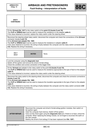
DF074
CONTINUED 3
RIGHT-HAND DRIVE
CC.1
CC.0
NOTESNone.
Lock the computer using the diagnostic tool.
Switch off engine and remove the glovebox.
Disconnect the 8-track intermediate connector from the passenger air bag and check the connections (tracks A5
and A6 behind the glove box).
Fit the 8-track test adapter Elé. 1617.
The CLIP or XRBAG tool must be used to measure the insulation appropriate to the type of fault on cable B of
the adapter.
Is the value obtained correct?
YES
Reconnect the 8-trackconnector.
Disconnect the computer and check the connector connections (tracks 1 and 12).
Fit the 22-track adapter Elé. 1685.
The CLIP or XRBAG tool must be used to measure the insulation appropriately for the
type of fault in adapter cable A.
If the value obtained is incorrect, the wiring is faulty between the computer and the
8-track connector (C0/C2).
Repair or replace the wiring harness if necessary.
NODisconnect the GREEN passenger airbag connector, connect 1 dummy ignition module
to the ignition module connector and check the insulation measurement again
appropriate to the type of fault on the adapter cable B.
– If the value obtained is correct, replace the passenger airbag.
– If the value obtained is incorrect, the wiring is faulty between points C2 and C4.
Repair or replace the wiring harness if necessary.
AFTER REPAIRReconnect the computer and driver's frontal airbag ignition modules, then switch
on the ignition again.
Clear the computer fault memory. Switch off the ignition.
Carry out the check again using the diagnostic tool and, if there is no fault, unlock
the computer. When replacing the airbag module, do not forget to reconnect the
earth on the new module.
Destroy the driver's front airbag if it has been replaced (tool Elé. 1287).
Page 50 of 88

88C-50
MR-372-J84-88C100$472.mif
V5
88C
AIRBAGS AND PRETENSIONERS
Fault finding – Interpretation of faults
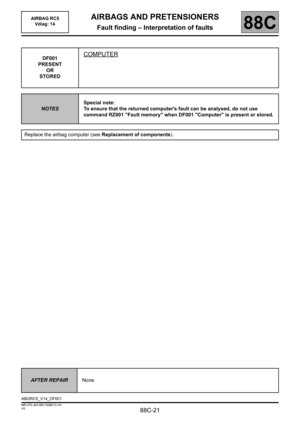
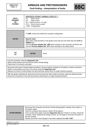
DF075
PRESENT
OR
STORED
PASSENGER FRONTAL AIRBAG CIRCUIT 1
CC: Short circuit
CO: Open circuit
CC.1: Short circuit to + 12 volts
CC.0: Short circuit to earth
1.DEF: Configuration
NOTESIf 1.DEF, check and modify the computer configuration.
Special notes:
Never carry out measuring on the trigger lines with any tool other than CLIP
or XRBAG.
Use the 22-track adapter Elé. 1685 when working on the computer connector.
LEFT-HAND DRIVE
Lock the computer using the diagnostic tool.
Switch off the ignition and check that the passenger airbag is connected correctly (access to the connectors via
the glovebox).
Disconnect the ORANGE connector for the passenger front air bag and connect 1 dummy ignition module to
the ignition module connector.
Switch on the ignition and carry out a check using the diagnostic tool.
Replace the passenger front airbag if the fault becomes stored (fault no longer declared present).
If the value is incorrect, disconnect the computer and check the connector connections (tracks 2 and 13).
Fit the 22-track adapter Elé. 1685.
The CLIP or XRBAG tool must be used to measure the resistance on cable B of the adapter.
If the value obtained is incorrect, the wiring is faulty between the computer and the passenger airbag connectors
(C0/C4). Replace the wiring if necessary.
If the value obtained is correct, check the computer connections again.
AFTER REPAIRReconnect the computer and driver's frontal airbag ignition modules, then switch on
the ignition again.
Clear the computer fault memory. Switch off the ignition.
Carry out the check again using the diagnostic tool and, if there is no fault, unlock
the computer. When replacing the airbag module, do not forget to reconnect the earth
on the new module.
Destroy the driver's front airbag if it has been replaced (tool Elé. 1287).
ABGRC5_V14_DF075
AIRBAG RC5
Vdiag: 14
Page 51 of 88

88C-51
MR-372-J84-88C100$472.mif
V5
AIRBAGS AND PRETENSIONERS
Fault finding – Interpretation of faults
AIRBAG RC5
Vdiag: 14
88C
DF075
CONTINUED 1
LEFT-HAND DRIVE
CC.1
CC.0
NOTESNone.
Lock the computer using the diagnostic tool.
Disconnect the computer and check the connector connections (tracks 1 and 12).
Fit the 22-track adapter Elé. 1685.
The CLIP or XRBAG tool must be used to measure the insulation appropriate to the type of fault on cable B
of the adapter.
If the value obtained is incorrect, the wiring is faulty between the computer and the passenger airbag connectors
(C0/C4).
Replace the wiring if necessary.
AFTER REPAIRReconnect the computer and driver's frontal airbag ignition modules, then switch on
the ignition again.
Clear the computer fault memory. Switch off the ignition.
Carry out the check again using the diagnostic tool and, if there is no fault, unlock
the computer. When replacing the airbag module, do not forget to reconnect the earth
on the new module.
Destroy the driver's front airbag if it has been replaced (tool Elé. 1287).
Page 52 of 88

88C-52
MR-372-J84-88C100$472.mif
V5
AIRBAG RC5
Vdiag: 14AIRBAGS AND PRETENSIONERS
Fault finding – Interpretation of faults88C
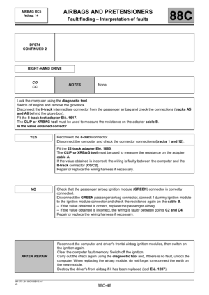
DF075
CONTINUED 2
RIGHT-HAND DRIVE
CO
CC
NOTESNone.
Lock the computer using the diagnostic tool.
Switch off engine and remove the glovebox.
Disconnect the 8-track intermediate connector from the passenger air bag and check the connections (tracks A7
and A8 behind the glove box).
Fit the 8-track test adapter Elé. 1617.
The CLIP or XRBAG tool must be used to measure the resistance on the adapter cable D.
Is the value obtained correct?
YES
Reconnect the 8-trackconnector.
Disconnect the computer and check the connector connections (tracks 2 and 13).
Fit the 22-track adapter Elé. 1685.
The CLIP or XRBAG tool must be used to measure the resistance on cable B of
the adapter.
If the value obtained is incorrect, the wiring is faulty between the computer
and the8-track connector (C0/C2).
Repair or replace the wiring harness if necessary.
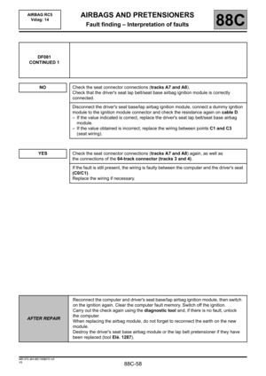
NOCheck that the passenger airbag ignition module (ORANGE) connector is correctly
connected.
Disconnect the ORANGE connector for the passenger airbag and connect 1 dummy
ignition module to the ignition module connector and measure the resistance again on
cable D.
– If the value obtained is correct, replace the passenger airbag.
– If the value obtained is incorrect, the wiring is faulty between points C2 and C4.
Repair or replace the wiring harness if necessary.
AFTER REPAIRReconnect the computer and driver's frontal airbag ignition modules, then switch on
the ignition again.
Clear the computer fault memory. Switch off the ignition.
Carry out the check again using the diagnostic tool and, if there is no fault, unlock
the computer. When replacing the airbag module, do not forget to reconnect the earth
on the new module.
Destroy the driver's front airbag if it has been replaced (tool Elé. 1287).
Page 53 of 88

88C-53
MR-372-J84-88C100$472.mif
V5
AIRBAG RC5
Vdiag: 14AIRBAGS AND PRETENSIONERS
Fault finding – Interpretation of faults88C
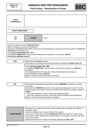
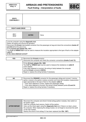
DF075
CONTINUED 3
RIGHT-HAND DRIVE
CC.1
CC.0
NOTESNone
Lock the computer using the diagnostic tool.
Switch off engine and remove the glovebox.
Disconnect the 8-track intermediate connector from the passenger air bag and check the connections (tracks A7
and A8 behind the glove box).
Fit the 8-track test adapter Elé. 1617.
The CLIP or XRBAG tool must be used to measure the insulation appropriate to the type of fault on the adapter
cable D.
Is the value obtained correct?
YES
Reconnect the 8-trackconnector.
Disconnect the computer and check the connector connections (tracks 2 and 13).
Fit the 22-track adapter Elé. 1685.
The CLIP or XRBAG tool must be used to measure the resistance on cable B
of the adapter.
If the value obtained is incorrect, the wiring is faulty between the computer
and the8-track connector (C0/C2).
Repair or replace the wiring harness if necessary.
NODisconnect the ORANGE connector for the passenger airbag and connect 1 dummy
ignition module to the ignition module connector and check the insulation measurement
again appropriate to the type of fault on the adapter cable D.
– If the value obtained is correct, replace the passenger airbag.
– If the value obtained is incorrect, the wiring is faulty between points C2 and C4.
Repair or replace the wiring harness if necessary.
AFTER REPAIRReconnect the computer and driver's frontal airbag ignition modules, then switch on
the ignition again.
Clear the computer fault memory. Switch off the ignition.
Carry out the check again using the diagnostic tool and, if there is no fault, unlock
the computer. When replacing the airbag module, do not forget to reconnect the earth
on the new module.
Destroy the driver's front airbag if it has been replaced (tool Elé. 1287).
Page 54 of 88

88C-54
MR-372-J84-88C100$472.mif
V5
AIRBAGS AND PRETENSIONERS
Fault finding – Interpretation of faults
AIRBAG RC5
Vdiag: 14
88C
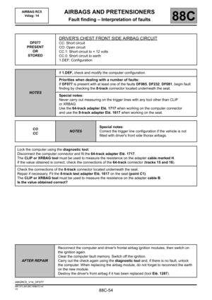
DF077
PRESENT
OR
STORED
DRIVER'S CHEST FRONT SIDE AIRBAG CIRCUIT
CC: Short circuit
CO: Open circuit
CC.1: Short circuit to + 12 volts
CC.0: Short circuit to earth
1.DEF: Configuration
NOTESIf 1.DEF, check and modify the computer configuration.
Priorities when dealing with a number of faults:
If DF077 is present with at least one of the faults DF065, DF232, DF081, begin fault
finding by checking the 8-track connector located underneath the seat.
Special notes:
Never carry out measuring on the trigger lines with any tool other than CLIP
or XRBAG.
Use the 64-track adapter Elé. 1717 when working on the computer connector
and use the 8-track adapter Elé. 1617 when working on the seat.
CO
CC
NOTESSpecial notes:
Correct the trigger line configuration if the vehicle is not
fitted with driver's front side thorax airbags.
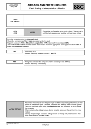
Lock the computer using the diagnostic tool.
Disconnect the computer connector and fit the 64-track adapter Elé. 1717.
The CLIP or XRBAG tool must be used to measure the resistance on the adapter cable marked H.
If the value obtained is correct, check the connections of the 64-track connector (tracks 15 and 16).
Check the connections of the 8-track connector located underneath the seat.
Repair if necessary. Fit the 8-track test adapter Elé. 1617 on the seat (point C1).
The CLIP or XRBAG tool must be used to measure the resistance on the adapter cable B.
Is the value obtained correct?
AFTER REPAIRReconnect the computer and driver's frontal airbag ignition modules, then switch on
the ignition again.
Clear the computer fault memory. Switch off the ignition.
Carry out the check again using the diagnostic tool and, if there is no fault, unlock
the computer. When replacing the airbag module, do not forget to reconnect the earth
on the new module.
Destroy the driver's front airbag if it has been replaced (tool Elé. 1287).
ABGRC5_V14_DF077
Page 55 of 88

88C-55
MR-372-J84-88C100$472.mif
V5
AIRBAG RC5
Vdiag: 14AIRBAGS AND PRETENSIONERS
Fault finding – Interpretation of faults88C
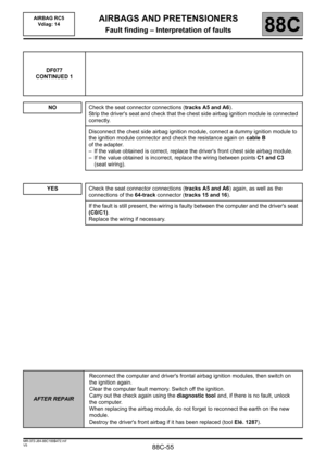
DF077
CONTINUED 1
NO
Check the seat connector connections (tracks A5 and A6).
Strip the driver's seat and check that the chest side airbag ignition module is connected
correctly.
Disconnect the chest side airbag ignition module, connect a dummy ignition module to
the ignition module connector and check the resistance again on cable B
of the adapter.
– If the value obtained is correct, replace the driver's front chest side airbag module.
– If the value obtained is incorrect, replace the wiring between points C1 and C3
(seat wiring).
YESCheck the seat connector connections (tracks A5 and A6) again, as well as the
connections of the 64-track connector (tracks 15 and 16).
If the fault is still present, the wiring is faulty between the computer and the driver's seat
(C0/C1).
Replace the wiring if necessary.
AFTER REPAIRReconnect the computer and driver's frontal airbag ignition modules, then switch on
the ignition again.
Clear the computer fault memory. Switch off the ignition.
Carry out the check again using the diagnostic tool and, if there is no fault, unlock
the computer.
When replacing the airbag module, do not forget to reconnect the earth on the new
module.
Destroy the driver's front airbag if it has been replaced (tool Elé. 1287).
Page 56 of 88

88C-56
MR-372-J84-88C100$472.mif
V5
AIRBAG RC5
Vdiag: 14AIRBAGS AND PRETENSIONERS
Fault finding – Interpretation of faults88C
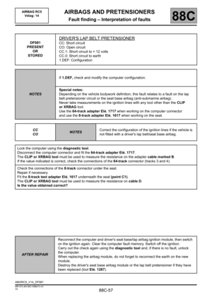
DF077
CONTINUED 2
CC.1
CC.0
NOTESNone.
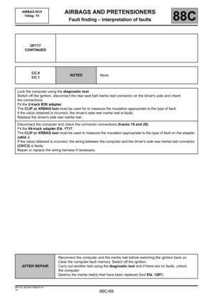
Lock the computer using the diagnostic tool.
Disconnect the computer connector and fit the 64-track adapter Elé. 1717.
The CLIP or XRBAG tool must be used to measure the insulation appropriate to the type of fault on the adapter
cable marked H.
If the value obtained is correct, check the connections of the 64-track connector (tracks 15 and 16).
Check the connections of the 8-track connector located underneath the seat. Repair if necessary. Fit the 8-track
test adapter Elé. 1617 underneath the seat (point C1).
The CLIP or XRBAG tool must be used to measure the insulation appropriate to the type of fault on the adapter
cable B.
Is the value obtained correct?
NO
Driver's seat wiring fault (C1/C3).
Replace the wiring harness between points C1 and C3 (seat wiring) if necessary.
YESCheck the seat connector connections (tracks A5 and A6) again, as well as
the connections of the 64-track connector (tracks 15 and 16).
If the fault is still present, the wiring is faulty between the computer and the driver's seat
(C0/C1).
Replace the wiring if necessary.
AFTER REPAIRReconnect the computer and driver's frontal airbag ignition modules, then switch on
the ignition again.
Clear the computer fault memory. Switch off the ignition.
Carry out the check again using the diagnostic tool and, if there is no fault, unlock
the computer.
When replacing the airbag module, do not forget to reconnect the earth on the new
module.
Destroy the driver's front airbag if it has been replaced (tool Elé. 1287).