Page 49 of 68

AIRBAG - SEAT BELT PRETENSIONERS
Fault finding - Fault Interpretation
88C - 49
88C
V3 MR-372-J84-88C000$072.mif
AIRBAG ACU4
Vdiag: 04
AIRBAG - SEAT BELT PRETENSIONERS
Fault finding - Fault Interpretation
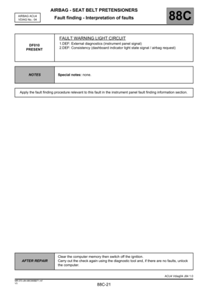
DF077
PRESENT
DRIVER'S CHEST FRONT SIDE AIRBAG CIRCUIT
CC : Short circuit
CO : Open circuit
CC.1 : Short circuit to + 12 V
CC.0 : Short circuit to earth
1.DEF : Configuration
NOTESIf 1.DEF, check and adjust the computer configuration.
Priorities when dealing with multiple faults: If DF077 is present with at least one of
DF065, DF210, DF232, or DF240, begin the fault finding by checking the 22-track
under-seat connector.
Special notes: never carry out measuring operations on trigger lines using any tool
other than CLIP or XRBAG.
Use the 64-track (Elé. 1717) adapter for working on the computer connector and the
22-track (Elé. 1687) adapter for working on the seat.
CO - CC
NOTESSpecial notes: correct the trigger line configuration if the
vehicle is not fitted with a driver's front chest side airbag.
Lock the computer, disconnect the computer connector and attach 64-track adapter (Elé. 1717). The CLIP or
XRBAG tool absolutely must be used to measure the resistance in the adapter cable marked H.
If the value indicated is correct, check the connections of the 64-track (tracks 15 and 16) connector.
Check the connections of the 22-track connector under the seat. Repair if necessary. Attach the 22-track
(Elé. 1687) test adapter under the seat (point C1).
The CLIP or XRBAG tool absolutely must be used to measure the resistance in cable A.
Is the value obtained correct?
NO
YES
Check the seat connector connections (tracks 11 and 12).
Remove the trim from the driver's seat and check that the chest side airbag ignition module is properly
connected.
Disconnect the chest side airbag ignition module, connect a dummy ignition module to the ignition
module connector and again measure the resistance in cable A.
– If the value obtained is correct, replace the driver's chest front side airbag module.
– If the value obtained is still not correct, replace the wiring between points C1 and C3 (seat wiring).
Check the seat connector connections (tracks 11 and 12) again, as well as those of the 64-track
(tracks 15 and 16) connector.
If the fault is still present, the wiring is faulty between the computer and the driver's seat (C0/C1).
Replace the wiring if necessary.
AFTER REPAIRReconnect the computer and the ignition module of the driver's front side airbag
module then switch on the ignition. Clear the computer memory then switch off the
ignition.
Carry out the check again using the diagnostic tool and, if there are no faults, unlock
the computer. When replacing the airbag module, do not forget to reconnect the earth
on the new one.
Destroy the chest side airbag module if it has been replaced (tool Elé. 1287).
ACU4 Vdiag04 J84 1.0
MR-372-J84-88C000$072.mif
Page 50 of 68

AIRBAG - SEAT BELT PRETENSIONERS
Fault finding - Fault Interpretation
88C - 50
88C
V3 MR-372-J84-88C000$072.mif
AIRBAG ACU4
Vdiag: 04
DF077
CONTINUED
CC.1 - CC.0
NOTESNone.
Lock the computer, disconnect the computer connector and attach 64-track adapter (Elé. 1717). The CLIP or
XRBAG tool absolutely must be used to measure the proper insulation for the type of fault in the adapter cable
marked H.
If the value indicated is correct, check the connections of the 64-track (tracks 15 and 16) connector.
Check the connections of the 22-track connector under the seat. Repair if necessary. Attach the 22-track
(Elé. 1687) test adapter under the seat (point C1).
The CLIP or XRBAG tool absolutely must be used to measure the proper insulation for the type of fault in
cable A.
Is the value obtained correct?
NO
YES
– Driver's seat wiring fault (C1/C3).
– Replace the wiring between points C1 and C3 (seat wiring) if necessary.
Check the seat connector connections (tracks 11 and 12) again, as well as those of
the 64-track (tracks 15 and 16) connector.
If the fault is still present, the wiring is faulty between the computer and the driver's
seat (C0/C1).
Replace the wiring if necessary.
AFTER REPAIRReconnect the computer and the ignition module of the driver's front side airbag
module then switch on the ignition. Clear the computer memory then switch off the
ignition.
Carry out the check again using the diagnostic tool and, if there are no faults, unlock
the computer. When replacing the airbag module, do not forget to reconnect the earth
on the new one.
Destroy the chest side airbag module if it has been replaced (tool Elé. 1287).
ACU4 Vdiag04 J84 1.0
Page 51 of 68

AIRBAG - SEAT BELT PRETENSIONERS
Fault finding - Fault Interpretation
88C - 51
88C
V3 MR-372-J84-88C000$072.mif
AIRBAG ACU4
Vdiag: 04
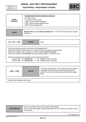
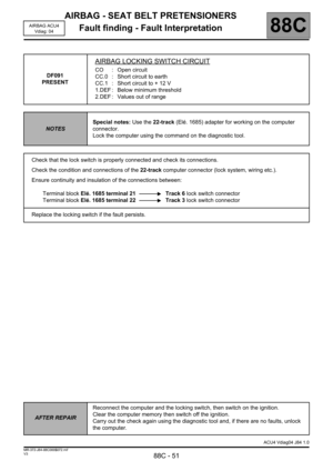
DF091
PRESENT
AIRBAG LOCKING SWITCH CIRCUIT
CO : Open circuit
CC.0 : Short circuit to earth
CC.1 : Short circuit to + 12 V
1.DEF : Below minimum threshold
2.DEF : Values out of range
NOTESSpecial notes: Use the 22-track (Elé. 1685) adapter for working on the computer
connector.
Lock the computer using the command on the diagnostic tool.
Check that the lock switch is properly connected and check its connections.
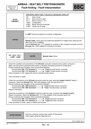
Check the condition and connections of the 22-track computer connector (lock system, wiring etc.).
Ensure continuity and insulation of the connections between:
Terminal block Elé. 1685 terminal 21 Track 6 lock switch connector
Terminal block Elé. 1685 terminal 22 Track 3 lock switch connector
Replace the locking switch if the fault persists.
AFTER REPAIRReconnect the computer and the locking switch, then switch on the ignition.
Clear the computer memory then switch off the ignition.
Carry out the check again using the diagnostic tool and, if there are no faults, unlock
the computer.
ACU4 Vdiag04 J84 1.0
Page 52 of 68
AIRBAG - SEAT BELT PRETENSIONERS
Fault finding - Fault Interpretation
88C - 52
88C
V3 MR-372-J84-88C000$072.mif
AIRBAG ACU4
Vdiag: 04
DF187
PRESENT
TRIGGER LINES CONFIGURATION
NOTESNone.
This fault indicates an inconsistency between the computer configuration and the vehicle equipment detected
by the computer. The computer has detected the presence of an element additional to its configuration.
Carry out a reading of the configuration under the heading "READING THE CONFIGURATION".
Modify the computer configuration, adapting it to the equipment level of the vehicle.
AFTER REPAIRClear the computer memory then switch off the ignition.
Check again using the diagnostic tool.
ACU4 Vdiag04 J84 1.0
Page 53 of 68
AIRBAG - SEAT BELT PRETENSIONERS
Fault finding - Fault Interpretation
88C - 53
88C
V3 MR-372-J84-88C000$072.mif
AIRBAG ACU4
Vdiag: 04
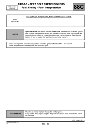
DF193
PRESENT
PASSENGER AIRBAG LOCKING CHANGE OF STATE
NOTESSpecial features: the vehicle user has 10 seconds after switching on + after ignition
feed to inhibit the passenger airbag with the switch. After this time, the computer will
store this fault and light up the warning light on the instrument panel. Switching the
ignition off and on erases this fault from the computer memory.
Set the locking switch to the desired position, switch the ignition off and wait for a few seconds.
Switch the ignition back on and check that the fault is gone.
AFTER REPAIRClear the computer memory then switch off the ignition.
Carry out the check again using the diagnostic tool and, if there are no faults, unlock
the computer.
ACU4 Vdiag04 J84 1.0
Page 54 of 68
AIRBAG - SEAT BELT PRETENSIONERS
Fault finding - Fault Interpretation
88C - 54
88C
V3 MR-372-J84-88C000$072.mif
AIRBAG ACU4
Vdiag: 04
DF194
PRESENT
COMPUTER TO BE REPLACED FOLLOWING IMPACT
NOTESNone.
Contact your Techline (see the "Replacing components" section for this procedure).
AFTER REPAIRNone
ACU4 Vdiag04 J84 1.0
Page 55 of 68

AIRBAG - SEAT BELT PRETENSIONERS
Fault finding - Fault Interpretation
88C - 55
88C
V3 MR-372-J84-88C000$072.mif
AIRBAG ACU4
Vdiag: 04
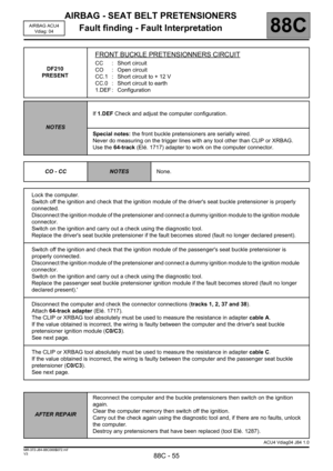
DF210
PRESENT
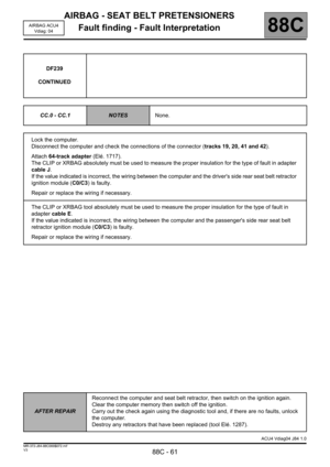
FRONT BUCKLE PRETENSIONNERS CIRCUIT
CC : Short circuit
CO : Open circuit
CC.1 : Short circuit to + 12 V
CC.0 : Short circuit to earth
1.DEF : Configuration
NOTESIf 1.DEF Check and adjust the computer configuration.
Special notes: the front buckle pretensioners are serially wired.
Never do measuring on the trigger lines with any tool other than CLIP or XRBAG.
Use the 64-track (Elé. 1717) adapter to work on the computer connector.
CO - CC
NOTESNone.
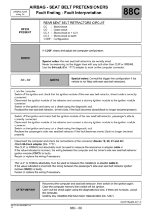
Lock the computer.
Switch off the ignition and check that the ignition module of the driver's seat buckle pretensioner is properly
connected.
Disconnect the ignition module of the pretensioner and connect a dummy ignition module to the ignition module
connector.
Switch on the ignition and carry out a check using the diagnostic tool.
Replace the driver's seat buckle pretensioner if the fault becomes stored (fault no longer declared present).
Switch off the ignition and check that the ignition module of the passenger's seat buckle pretensioner is
properly connected.
Disconnect the ignition module of the pretensioner and connect a dummy ignition module to the ignition module
connector.
Switch on the ignition and carry out a check using the diagnostic tool.
Replace the passenger seat buckle pretensioner ignition module if the fault becomes stored (fault no longer
declared present).'
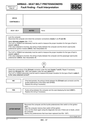
Disconnect the computer and check the connector connections (tracks 1, 2, 37 and 38).
Attach 64-track adapter (Elé. 1717).
The CLIP or XRBAG tool absolutely must be used to measure the resistance in adapter cable A.
If the value obtained is incorrect, the wiring is faulty between the computer and the driver's seat buckle
pretensioner ignition module (C0/C3).
See next page.
The CLIP or XRBAG tool absolutely must be used to measure the resistance in adapter cable C.
If the value obtained is incorrect, the wiring is faulty between the computer and the passenger seat buckle
pretensioner (C0/C3).
See next page.
AFTER REPAIRReconnect the computer and the buckle pretensioners then switch on the ignition
again.
Clear the computer memory then switch off the ignition.
Carry out the check again using the diagnostic tool and, if there are no faults, unlock
the computer.
Destroy any pretensioners that have been replaced (tool Elé. 1287).
ACU4 Vdiag04 J84 1.0
Page 56 of 68

AIRBAG - SEAT BELT PRETENSIONERS
Fault finding - Fault Interpretation
88C - 56
88C
V3 MR-372-J84-88C000$072.mif
AIRBAG ACU4
Vdiag: 04
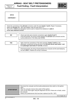
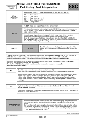
DF210
CONTINUED 1
Check the connections of the 22-track connector under the seat (tracks 7 and 8). Repair if necessary.
Attach the 22-track (Elé. 1687) test adapter under the seat (point C1).
The CLIP or XRBAG tool absolutely must be used to measure the resistance in cable C.
Is the value obtained correct?
NO
YES
Check seat side seat connector connections again (tracks 8 and 7).
If the fault persists, the wiring is faulty between the 22-track seat connector and the
buckle pretensioner of the faulty seat (C1/C3).
Again check the connections of the seat connector (tracks 7 and 8) on the
passenger compartment wiring side and of the 64-track (driver seat tracks 1 and
2 or passenger seat tracks 37 and 38) connector.
If the fault persists, the wiring is faulty between the computer and the seat displaying
the fault (C0/C1). Replace the wiring if necessary.
AFTER REPAIRReconnect the computer and the buckle pretensioners then switch on the ignition
again.
Clear the computer memory then switch off the ignition.
Carry out the check again using the diagnostic tool and, if there are no faults, unlock
the computer.
Destroy any pretensioners that have been replaced (tool Elé. 1287).
ACU4 Vdiag04 J84 1.0