Page 25 of 68

AIRBAG - SEAT BELT PRETENSIONERS
Fault finding - Interpretation of faults
88C-25
88C
V3 MR-372-J84-88C000$071.mif
AIRBAG ACU4
VDIAG No.: 04
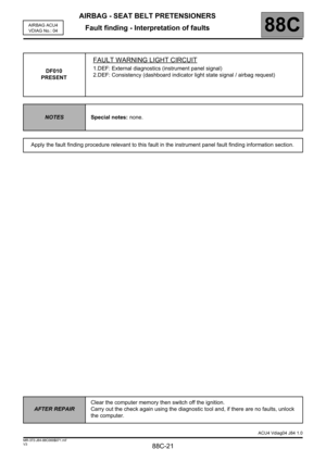
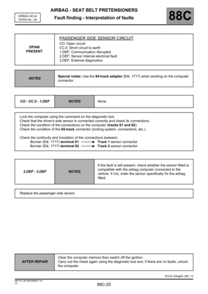
DF040
PRESENT
PASSENGER SIDE SENSOR CIRCUIT
CO: Open circuit
CC.0: Short circuit to earth
1.DEF: Communication disrupted
2.DEF: Sensor internal electrical fault
3.DEF: External diagnostics
NOTESSpecial notes: Use the 64-track adapter (Elé. 1717) when working on the computer
connector.
CO - CC.0 - 1.DEF
NOTESNone.
Lock the computer using the command on the diagnostic tool.
Check that the driver's side sensor is connected correctly and check its connections.
Check the condition of the connections on the computer (tracks 61 and 62).
Check the condition of the 64-track connector (locking system, connections, etc.).
Check the continuity and insulation of the connections between:
Bornier (Elé. 1717) terminal 61 Track 1 sensor connector
Bornier (Elé. 1717) terminal 62 Track 2 sensor connector
2.DEF - 3.DEF
NOTESIf the fault is still present, check whether the sensor fitted is
compatible with the airbag computer connected to the
vehicle. If not, order the sensor specifically for the airbag
fitted.
Replace the passenger side sensor.
AFTER REPAIRClear the computer memory then switch off the ignition.
Carry out the check again using the diagnostic tool and, if there are no faults, unlock
the computer.
ACU4 Vdiag04 J84 1.0
Page 26 of 68
AIRBAG - SEAT BELT PRETENSIONERS
Fault finding - Interpretation of faults
88C-26
88C
V3 MR-372-J84-88C000$071.mif
AIRBAG ACU4
VDIAG No.: 04
DF051
PRESENT
DRIVER'S SIDE SENSOR CONFIGURATION
NOTESSpecial notes: none.
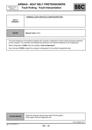
This fault corresponds to an inconsistency between the computer configuration and the vehicle equipment
detected by the computer. The computer has detected the presence of a component additional to its
configuration.
Read configuration LC025 under the heading Read configuration.
Use command CF207 to modify the computer configuration to the vehicle's equipment level.
AFTER REPAIRClear the computer memory then switch off the ignition.
Carry out the check again using the diagnostic tool and, if there are no faults, unlock
the computer.
ACU4 Vdiag04 J84 1.0
Page 27 of 68
AIRBAG - SEAT BELT PRETENSIONERS
Fault finding - Interpretation of faults
88C-27
88C
V3 MR-372-J84-88C000$071.mif
AIRBAG ACU4
VDIAG No.: 04
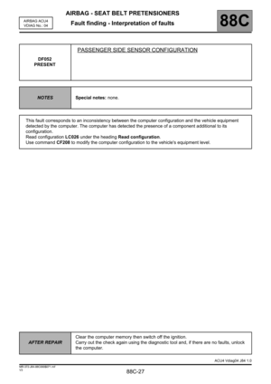
DF052
PRESENT
PASSENGER SIDE SENSOR CONFIGURATION
NOTESSpecial notes: none.
This fault corresponds to an inconsistency between the computer configuration and the vehicle equipment
detected by the computer. The computer has detected the presence of a component additional to its
configuration.
Read configuration LC026 under the heading Read configuration.
Use command CF208 to modify the computer configuration to the vehicle's equipment level.
AFTER REPAIRClear the computer memory then switch off the ignition.
Carry out the check again using the diagnostic tool and, if there are no faults, unlock
the computer.
ACU4 Vdiag04 J84 1.0
Page 28 of 68
AIRBAG - SEAT BELT PRETENSIONERS
Fault finding - Interpretation of faults
88C-28
88C
V3 MR-372-J84-88C000$071.mif
AIRBAG ACU4
VDIAG No.: 04
DF053
PRESENT
DRIVER'S SEAT POSITION SENSOR CONFIGURATION
NOTESSpecial notes: none.
This fault corresponds to an inconsistency between the computer configuration and the vehicle equipment
detected by the computer. The computer has detected the presence of a component additional to its
configuration.
Read configuration LC086 under the heading Read configuration.
Use command CF289 to modify the computer configuration to the vehicle's equipment level.
AFTER REPAIRClear the computer memory then switch off the ignition.
Carry out the check again using the diagnostic tool and, if there are no faults, unlock
the computer.
ACU4 Vdiag04 J84 1.0
Page 29 of 68
AIRBAG - SEAT BELT PRETENSIONERS
Fault finding - Interpretation of faults
88C-29
88C
V3 MR-372-J84-88C000$071.mif
AIRBAG ACU4
VDIAG No.: 04
DF060
PRESENT
MULTIPLEX NETWORK
1.DEF: Carry out the multiplex network fault finding procedure
NOTESNone.
Apply the fault finding procedure for the multiplex network.
AFTER REPAIRClear the computer memory then switch off the ignition.
Check again using the diagnostic tool.
ACU4 Vdiag04 J84 1.0
Page 30 of 68

AIRBAG - SEAT BELT PRETENSIONERS
Fault finding - Interpretation of faults
88C-30
88C
V3 MR-372-J84-88C000$071.mif
AIRBAG ACU4
VDIAG No.: 04
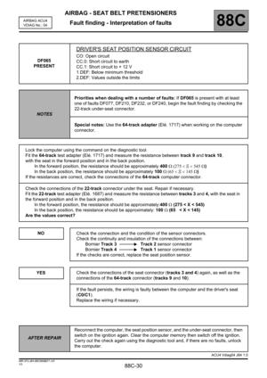
DF065
PRESENT
DRIVER'S SEAT POSITION SENSOR CIRCUIT
CO: Open circuit
CC.0: Short circuit to earth
CC.1: Short circuit to + 12 V
1.DEF: Below minimum threshold
2.DEF: Values outside the limits
NOTESPriorities when dealing with a number of faults: If DF065 is present with at least
one of faults DF077, DF210, DF232, or DF240, begin the fault finding by checking the
22-track under-seat connector.
Special notes: Use the 64-track adapter (Elé. 1717) when working on the computer
connector.
Lock the computer using the command on the diagnostic tool.
Fit the 64-track test adapter (Elé. 1717) and measure the resistance between track 9 and track 10,
with the seat in the forward position and in the back position.
In the forward position, the resistance should be approximately 400Ω (275 < Ξ < 545 Ω)
In the back position, the resistance should be approximately 100Ω (65 < Ξ < 145 Ω)
If the resistances are correct, check the connections of the 64-track computer connector.
Check the connections of the 22-track connector under the seat. Repair if necessary.
Fit the 22-track test adapter (Elé. 1687) and measure the resistance between tracks 3 and 4, with the seat in
the forward position and in the back position.
In the forward position, the resistance should be approximately:400Ω (275 < X < 545)
In the back position, the resistance should be approximately: 100Ω (65 < X < 145)
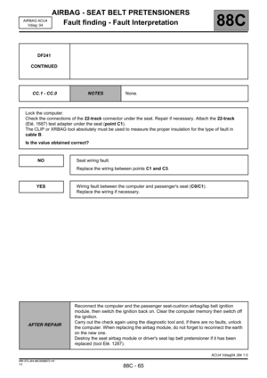
Are the values correct?
NO
YES
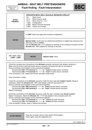
Check the connection and the condition of the sensor connectors.
Check the continuity and insulation of the connections between:
Bornier Track 3 Track 2 sensor connector
Bornier Track 4 Track 1 sensor connector
If the checks are correct, replace the seat position sensor.
Check the connections of the seat connector (tracks 3 and 4) again, as well as the
connections of the 64-track connector (tracks 9 and 10).
If the fault persists, the wiring is faulty between the computer and the driver's seat
(C0/C1).
Replace the wiring if necessary.
AFTER REPAIRReconnect the computer, the seat position sensor, and the under-seat connector, then
switch on the ignition again. Clear the computer memory then switch off the ignition.
Carry out the check again using the diagnostic tool and, if there are no faults, unlock
the computer.
ACU4 Vdiag04 J84 1.0
Page 31 of 68

AIRBAG - SEAT BELT PRETENSIONERS
Fault finding - Interpretation of faults
88C-31
88C
V3 MR-372-J84-88C000$071.mif
AIRBAG ACU4
VDIAG No.: 04
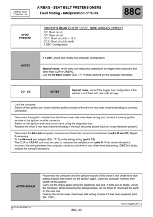
DF066
PRESENT
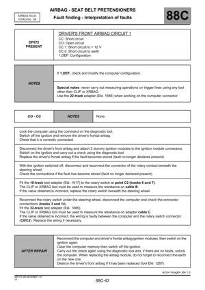
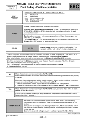
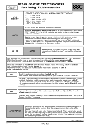
PASSENGER REAR CHEST LEVEL SIDE AIRBAG CIRCUIT
CC: Short circuit
CO: Open circuit
CC.1: Short circuit to + 12 V
CC.0: Short circuit to earth
1.DEF: Configuration
NOTESIf 1.DEF, check and modify the computer configuration.
Special notes: never carry out measuring operations on trigger lines using any tool
other than CLIP or XRBAG.
Use the 64-track adapter (Elé. 1717) when working on the computer connector.
CO - CC
NOTESSpecial notes: correct the trigger line configuration if the
vehicle is not fitted with rear side airbags.
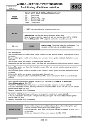
Lock the computer.
Switch off the ignition and check that the ignition module of the passenger's rear side chest-level airbag is
correctly connected.
Disconnect the ignition module from the passenger's rear side chest-level airbag and connect a dummy ignition
module to the ignition module connector.
Switch on the ignition and carry out a check using the diagnostic tool.
Replace the passenger's rear side chest-level airbag if the fault becomes stored (fault no longer declared
present).
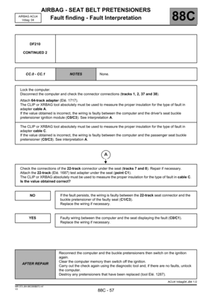
Disconnect the 64-track computer connector and check the connector connections (tracks 57 and 58). Repair
if necessary.
Fit the 64-track test adapter (Elé. 1717) to the airbag wiring (point C0).
The CLIP or XRBAG tool must be used to measure the resistance on cable L. If the value obtained is incorrect,
the wiring between the computer connector and passenger rear chest-level side airbag (C0/C3) is faulty;
replace the wiring if necessary.
AFTER REPAIRReconnect the computer and the ignition module of the passenger's rear chest-level
side airbag module then switch on the ignition again. Clear the computer memory then
switch off the ignition.
Carry out the check again using the diagnostic tool and, if there are no faults, unlock
the computer. When replacing the airbag module, do not forget to reconnect the earth
on the new one.
Destroy the passenger rear chest-level side airbag module if it has been replaced
(tool Elé. 1287).
ACU4 Vdiag04 J84 1.0
Page 32 of 68

AIRBAG - SEAT BELT PRETENSIONERS
Fault finding - Interpretation of faults
88C-32
88C
V3 MR-372-J84-88C000$071.mif
AIRBAG ACU4
VDIAG No.: 04
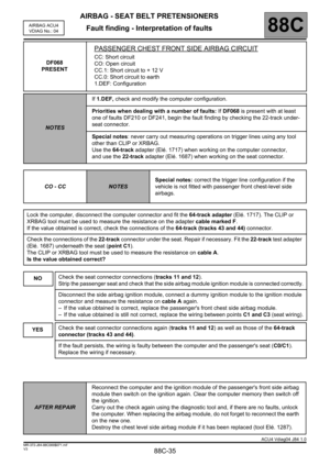
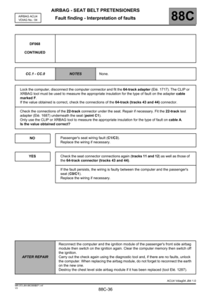
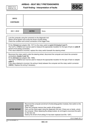
DF066
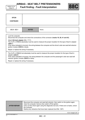
CONTINUED
CC.1 - CC.0
NOTESNone.
Lock the computer.
Disconnect the 64-track computer connector and check the connector connections (tracks 57 and 58). Repair
if necessary.
Fit the 64-track test adapter (Elé. 1717) to the airbag wiring (point C0).
The CLIP or XRBAG tool must be used to measure the appropriate insulation for the type of fault on cable L.
If the value obtained is incorrect, the wiring between the computer connector and passenger rear chest-level
side airbag (C0/C3) is faulty; replace the wiring if necessary.
AFTER REPAIRReconnect the computer and the ignition module of the passenger's rear chest-level
side airbag module then switch on the ignition again. Clear the computer memory then
switch off the ignition.
Carry out the check again using the diagnostic tool and, if there are no faults, unlock
the computer. When replacing the airbag module, do not forget to reconnect the earth
on the new one.
Destroy the passenger rear chest-level side airbag module if it has been replaced
(tool Elé. 1287).
ACU4 Vdiag04 J84 1.0