2011 NISSAN TIIDA oil pan
[x] Cancel search: oil panPage 26 of 3787
PRECAUTIONSAT-9
< SERVICE INFORMATION >
DE
F
G H
I
J
K L
M A
B
AT
N
O P
• Gaskets, seals and O-rings should be replaced any time the A/T is disassembled.
• It is very important to perform func tional tests whenever they are indicated.
• The valve body contains precision parts and requires extreme care when parts are removed and serviced.
Place disassembled valve body parts in order for easier and proper assembly. Care will also prevent springs
and small parts from becoming scattered or lost.
• Properly installed valves, sleeves, plugs, etc. will slide along bores in valve body under their own weight.
• Before assembly, apply a coat of recommended ATF to all parts. Apply petroleum jelly to protect O-rings and seals, or hold bearings and washers in pl ace during assembly. Do not use grease.
• Extreme care should be taken to avoid damage to O-rings, seals and gaskets when assembling.
• Clean or replace ATF cooler if excessive foreign material is found in oil pan or clogging strainer. Refer to AT-
18, "A/T Fluid Cooler Cleaning".
• After overhaul, refill the A/T with new ATF.
• When the A/T drain plug is removed, only some of the fluid is drained. Old A/T fluid will remain in torque con- verter and ATF cooling system.
Always follow the procedures under “Changing A/T Fluid” in the AT section when changing A/T fluid. Refer to
AT-17, "
Changing A/T Fluid", AT-17, "Checking A/T Fluid".
Service Notice or PrecautionINFOID:0000000005928067
ATF COOLER SERVICE
If A/T fluid contains frictional material (clutches, bands, etc.), or if an A/T is repaired, overhauled, or replaced,
inspect and clean the A/T oil cooler mounted in the radiator or replace the radiator. Flush cooler lines using
cleaning solvent and compressed air after repair. Check Service Bulletins for latest A/T oil cooler cleaning pro-
cedure. For radiator replacement, refer to CO-16, "
Removal and Installation" (HR16DE engine models), CO-
40, "Removal and Installation" (MR18DE engine models).
TORQUE CONVERTER SERVICE
The torque converter should be replaced under any of the following conditions:
• External leaks in the hub weld area.
• Converter hub is scored or damaged.
• Converter pilot is broken, damaged or fits poorly into crankshaft.
• Steel particles are found after flushing the cooler and cooler lines.
• Pump is damaged or steel particles are found in the converter.
• Vehicle has TCC shudder and/or no TCC apply. Replace only after all hydraulic and electrical diagnoses
have been made. (Converter clutch material may be glazed.)
• Converter is contaminated with engi ne coolant containing antifreeze.
• Internal malfunction of stator roller clutch.
• Heavy clutch debris due to overheating (blue converter).
• Steel particles or clutch lining material found in flui d filter or on magnet when no internal parts in unit are
worn or damaged — indicates that lining material came from converter.
The torque converter should not be replaced if:
• The fluid has an odor, is discolored, and there is no evidence of metal or clutch facing particles.
• The threads in one or more of the converter bolt holes are damaged.
• A/T malfunction did not display evidence of damaged or worn internal parts, steel particles or clutch plate lin-
ing material in unit and inside the fluid filter.
• Vehicle has been exposed to high mileage (only). The e xception may be where the torque converter clutch
dampener plate lining has seen excess wear by vehicles operated in heavy and/or constant traffic, such as
taxi, delivery or police use.
OBD-II SELF-DIAGNOSIS
• A/T self-diagnosis is performed by the TCM in combination with the ECM. The results can be read through the blinking pattern of the OD OFF indicator lamp or the malfunction indicator lamp (MIL). Refer to the table
on AT-82, "
Diagnosis Procedure without CONSULT-III" for the indicator used to display each self-diagnostic
result.
• The self-diagnostic results indicated by the MIL are automatically stored in both the ECM and TCM memo- ries.
Always perform the procedure “HOW TO ERASE DTC” on AT-39, "
OBD-II Diagnostic Trouble Code
(DTC)" to complete the repair and avoid unnecessary blinking of the MIL.
• The following self-diagnostic items can be detected us ing ECM self-diagnostic results mode* only when the
OD OFF indicator lamp does not indicate any malfunctions.
- Transmission range switch
- A/T 1GR, 2GR, 3GR, or 4GR function
Revision: May 2010 2011 Versa
Page 35 of 3787
AT-18
< SERVICE INFORMATION >
A/T FLUID
5. Run engine at idle speed for 5 minutes.
6. Check A/T fluid level and condition. Refer to AT-17, "
Checking A/T Fluid".
A/T Fluid Cooler CleaningINFOID:0000000005928072
Whenever the A/T is repaired, overhauled, or replaced, the A/T fluid cooler mounted in the radiator must be
inspected and cleaned.
Metal debris and friction material, if present, can becom e trapped in the A/T fluid cooler. This debris can con-
taminate the newly serviced A/T or, in severe cases, can bloc k or restrict the flow of A/T fluid. In either case,
malfunction of the newly serviced A/T may result.
Debris, if present, may build up as A/T fluid enters the c ooler inlet. It will be necessary to back flush the cooler
through the cooler outlet in order to flush out any built up debris.
A/T FLUID COOLER CLEANING PROCEDURE
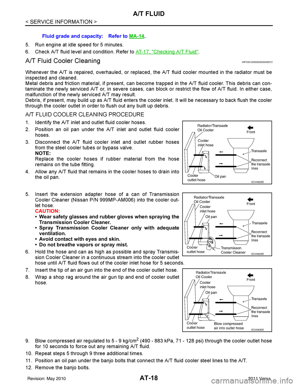
1. Identify the A/T inlet and outlet fluid cooler hoses.
2. Position an oil pan under the A/T inlet and outlet fluid cooler hoses.
3. Disconnect the A/T fluid cooler inlet and outlet rubber hoses from the steel cooler tubes or bypass valve.
NOTE:
Replace the cooler hoses if rubber material from the hose
remains on the tube fitting.
4. Allow any A/T fluid that remains in the cooler hoses to drain into the oil pan.
5. Insert the extension adapter hose of a can of Transmission
Cooler Cleaner (Nissan P/N 999MP-AM006) into the cooler out-
let hose.
CAUTION:
• Wear safety glasses and rubber gloves when spraying the Transmission Cooler Cleaner.
• Spray Transmission Cooler Cleaner only with adequate
ventilation.
• Avoid contact with eyes and skin.
• Do not breathe vapors or spray mist.
6. Hold the hose and can as high as possible and spray Transmis- sion Cooler Cleaner in a continuous stream into the cooler outlet
hose until A/T fluid flows out of t he cooler inlet hose for 5 seconds.
7. Insert the tip of an air gun into the end of the cooler outlet hose.
8. Wrap a shop rag around the air gun tip and end of cooler outlet hose.
9. Blow compressed air regulated to 5 - 9 kg/cm
2 (490 - 883 kPa, 71 - 128 psi) through the cooler outlet hose
for 10 seconds to force out any remaining A/T fluid.
10. Repeat steps 5 through 9 three additional times.
11. Position an oil pan under the banjo bolts that connec t the A/T fluid cooler steel lines to the A/T.
12. Remove the banjo bolts. Fluid grade and capacity: Refer to
MA-14
.
SCIA5628E
SCIA5629E
SCIA5630E
Revision: May 2010 2011 Versa
Page 36 of 3787
A/T FLUIDAT-19
< SERVICE INFORMATION >
DE
F
G H
I
J
K L
M A
B
AT
N
O P
13. Flush each steel line from the cooler side back toward the A/T by spraying Transmission Cooler Cleaner in a continuous stream for 5 seconds.
14. Blow compressed air regulated to 5 - 9 kg/cm
2 (490 - 883 kPa, 71 - 128 psi) through each steel line from
the cooler side back toward the A/T for 10 seconds to force out any remaining A/T fluid.
15. Ensure all debris is removed from the steel cooler lines.
16. Ensure all debris is removed from the banjo bolts and fittings.
17. Perform "A/T FLUID COOL ER DIAGNOSIS PROCEDURE".
A/T FLUID COOLER DIAGNOSIS PROCEDURE
NOTE:
Insufficient cleaning of the cooler inlet hose exte rior may lead to inaccurate debris identification.
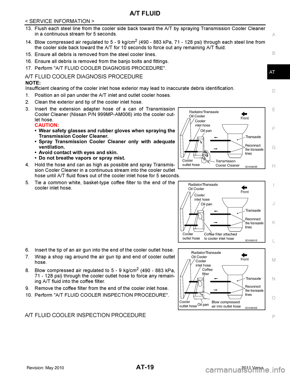
1. Position an oil pan under the A/T inlet and outlet cooler hoses.
2. Clean the exterior and tip of the cooler inlet hose.
3. Insert the extension adapter hose of a can of Transmission Cooler Cleaner (Nissan P/N 999MP-AM006) into the cooler out-
let hose.
CAUTION:
• Wear safety glasses and rubber gloves when spraying the
Transmission Cooler Cleaner.
• Spray Transmission Cooler Cleaner only with adequate
ventilation.
• Avoid contact with eyes and skin.
• Do not breathe vapors or spray mist.
4. Hold the hose and can as high as possible and spray Transmis- sion Cooler Cleaner in a continuous stream into the cooler outlet
hose until A/T fluid flows out of t he cooler inlet hose for 5 seconds.
5. Tie a common white, basket-type coffee filter to the end of the cooler inlet hose.
6. Insert the tip of an air gun into the end of the cooler outlet hose.
7. Wrap a shop rag around the air gun tip and end of cooler outlet hose.
8. Blow compressed air regulated to 5 - 9 kg/cm
2 (490 - 883 kPa,
71 - 128 psi) through the cooler outlet hose to force any remain-
ing A/T fluid into the coffee filter.
9. Remove the coffee filter from the end of the cooler inlet hose.
10. Perform "A/T FLUID COOL ER INSPECTION PROCEDURE".
A/T FLUID COOLER INSPECTION PROCEDURE
SCIA5629E
SCIA5631E
SCIA5632E
Revision: May 2010 2011 Versa
Page 115 of 3787
AT-98
< SERVICE INFORMATION >
P0710 TRANSMISSION FLUID TEMPERATURE SENSOR A
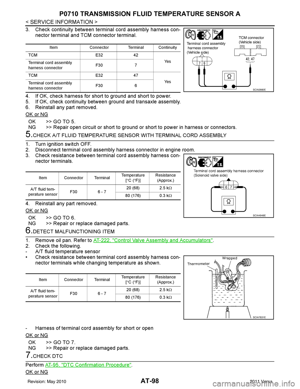
3. Check continuity between terminal cord assembly harness con-
nector terminal and TCM connector terminal.
4. If OK, check harness for short to ground and short to power.
5. If OK, check continuity bet ween ground and transaxle assembly.
6. Reinstall any part removed.
OK or NG
OK >> GO TO 5.
NG >> Repair open circuit or short to ground or short to power in harness or connectors.
5.CHECK A/T FLUID TEMPERATURE SENSO R WITH TERMINAL CORD ASSEMBLY
1. Turn ignition switch OFF.
2. Disconnect terminal cord assembly harness connector in engine room.
3. Check resistance between terminal cord assembly harness con- nector terminals.
4. Reinstall any part removed.
OK or NG
OK >> GO TO 6.
NG >> Repair or replace damaged parts.
6.DETECT MALFUNCTIONING ITEM
1. Remove oil pan. Refer to AT-222, "
Control Valve Assembly and Accumulators".
2. Check the following.
- A/T fluid temperature sensor
• Check resistance between terminal cord assembly harness con- nector terminals while changing temperature as shown.
- Harness of terminal cord assembly for short or open
OK or NG
OK >> GO TO 7.
NG >> Repair or replace damaged parts.
7.CHECK DTC
Perform AT-95, "
DTC Confirmation Procedure".
OK or NG
Item Connector Terminal Continuity
TCM E3242
Ye s
Terminal cord assembly
harness connector F30
7
TCM E3247
Ye s
Terminal cord assembly
harness connector F30
6
SCIA2660E
Item Connector Terminal Temperature
[° C ( °F)] Resistance
(Approx.)
A/T fluid tem-
perature sensor F30 6 - 7 20 (68) 2.5 k
Ω
80 (176) 0.3 kΩ
SCIA4948E
Item Connector Terminal Temperature
[° C ( °F)] Resistance
(Approx.)
A/T fluid tem-
perature sensor F30 6 - 7 20 (68) 2.5 k
Ω
80 (176) 0.3 kΩ
SCIA7831E
Revision: May 2010 2011 Versa
Page 116 of 3787
P0710 TRANSMISSION FLUID TEMPERATURE SENSOR AAT-99
< SERVICE INFORMATION >
DE
F
G H
I
J
K L
M A
B
AT
N
O P
OK >> INSPECTION END
NG >> GO TO 8.
8.CHECK TCM
1. Check TCM input/output signal. Refer to AT-75, "
TCM Terminal and Reference Value".
2. If NG, recheck TCM pin terminals for dam age or loose connection with harness connector.
OK or NG
OK >> INSPECTION END
NG >> Repair or replace damaged parts.
Component InspectionINFOID:0000000005928128
A/T FLUID TEMPERATURE SENSOR
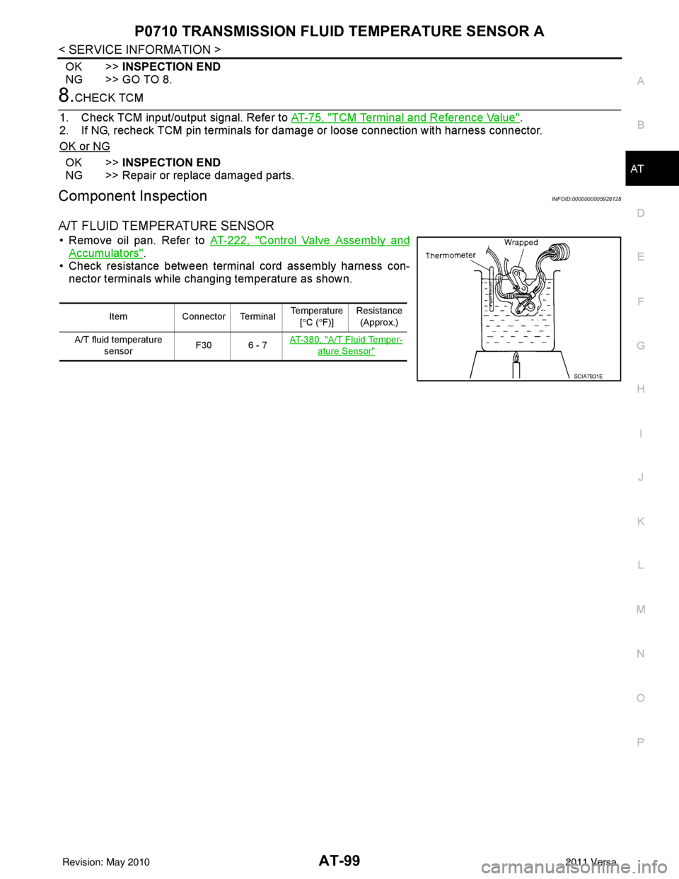
• Remove oil pan. Refer to AT-222, "Control Valve Assembly and
Accumulators".
• Check resistance between terminal cord assembly harness con-
nector terminals while changing temperature as shown.
Item Connector Terminal Temperature
[° C ( °F)] Resistance
(Approx.)
A/T fluid temperature sensor F30 6 - 7
AT- 3 8 0 , "
A/T Fluid Temper-
ature Sensor"
SCIA7831E
Revision: May 2010
2011 Versa
Page 177 of 3787
AT-160
< SERVICE INFORMATION >
BATT/FLUID TEMP SEN
OK >> GO TO 7.
NG >> Repair open circuit or short to ground or short to power in harness or connectors.
7.CHECK A/T FLUID TEMPERATURE SENSOR WITH TERMINAL CORD ASSEMBLY
1. Turn ignition switch OFF.
2. Disconnect terminal cord assembly connector in engine room.
3. Check resistance between terminal cord assembly terminals.
4. Reinstall any part removed.
OK or NG
OK >> GO TO 8.
NG >> Repair or replace damaged parts.
8.DETECT MALFUNCTIONING ITEM
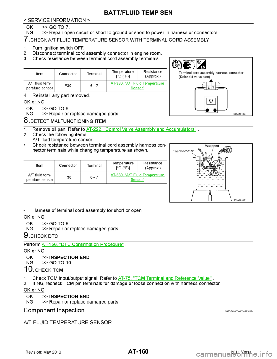
1. Remove oil pan. Refer to AT-222, "
Control Valve Assembly and Accumulators" .
2. Check the following items:
- A/T fluid temperature sensor
• Check resistance between terminal cord assembly harness con- nector terminals while changing temperature as shown.
- Harness of terminal cord assembly for short or open
OK or NG
OK >> GO TO 9.
NG >> Repair or replace damaged parts.
9.CHECK DTC
Perform AT-156, "
DTC Confirmation Procedure" .
OK or NG
OK >> INSPECTION END
NG >> GO TO 10.
10.CHECK TCM
1. Check TCM input/output signal. Refer to AT-75, "
TCM Terminal and Reference Value" .
2. If NG, recheck TCM pin terminals for damage or loose connection with harness connector.
OK or NG
OK >> INSPECTION END
NG >> Repair or replace damaged parts.
Component InspectionINFOID:0000000005928224
A/T FLUID TEMPERATURE SENSOR
Item Connector Terminal Temperature
[° C ( °F)] Resistance
(Approx.)
A/T fluid tem-
perature sensor F30 6 - 7 AT- 3 8 0 , "
A/T Fluid Temperature
Sensor"
SCIA4948E
Item Connector Terminal Temperature
[° C ( °F)] Resistance
(Approx.)
A/T fluid tem-
perature sensor F30 6 - 7 AT- 3 8 0 , "
A/T Fluid Temperature
Sensor"
SCIA7831E
Revision: May 2010
2011 Versa
Page 178 of 3787

BATT/FLUID TEMP SENAT-161
< SERVICE INFORMATION >
DE
F
G H
I
J
K L
M A
B
AT
N
O P
• Remove oil pan. Refer to AT-222, "Control Valve Assembly and
Accumulators" .
• Check resistance between terminal cord assembly harness con-
nector terminals while changing temperature as shown.
Item Connector Terminal Temperature
[° C ( °F)] Resistance
(Approx.)
A/T fluid tem-
perature sensor F30 6 - 7 AT- 3 8 0 , "
A/T Fluid Temperature
Sensor"
SCIA7831E
Revision: May 2010
2011 Versa
Page 200 of 3787
TROUBLE DIAGNOSIS FOR SYMPTOMSAT-183
< SERVICE INFORMATION >
DE
F
G H
I
J
K L
M A
B
AT
N
O P
NG >> 1. Check transmission range switch (Refer to test group 1.) again after adjusting transmission
range switch (Refer to AT-225
).
- If OK, INSPECTION END
- If NG, repair or replace transmission range switch. Refer to AT-225, "
Transmission Range
Switch" .
3.CHECK STARTING SYSTEM
Check starting system. Refer to SC-9
.
OK or NG
OK >> INSPECTION END
NG >> Repair or replace damaged parts.
In "P" Position, Vehicle Moves Forward or Backward When PushedINFOID:0000000005928249
SYMPTOM:
Vehicle moves when it is pushed forward or backward with selector lever in “P” position.
DIAGNOSTIC PROCEDURE
1.CHECK A/T POSITION
Check A/T position. Refer to AT-217, "
Checking of A/T Position" .
OK or NG
OK >> GO TO 2.
NG >> Adjust A/T position. Refer to AT-217, "
Adjustment of A/T Position" .
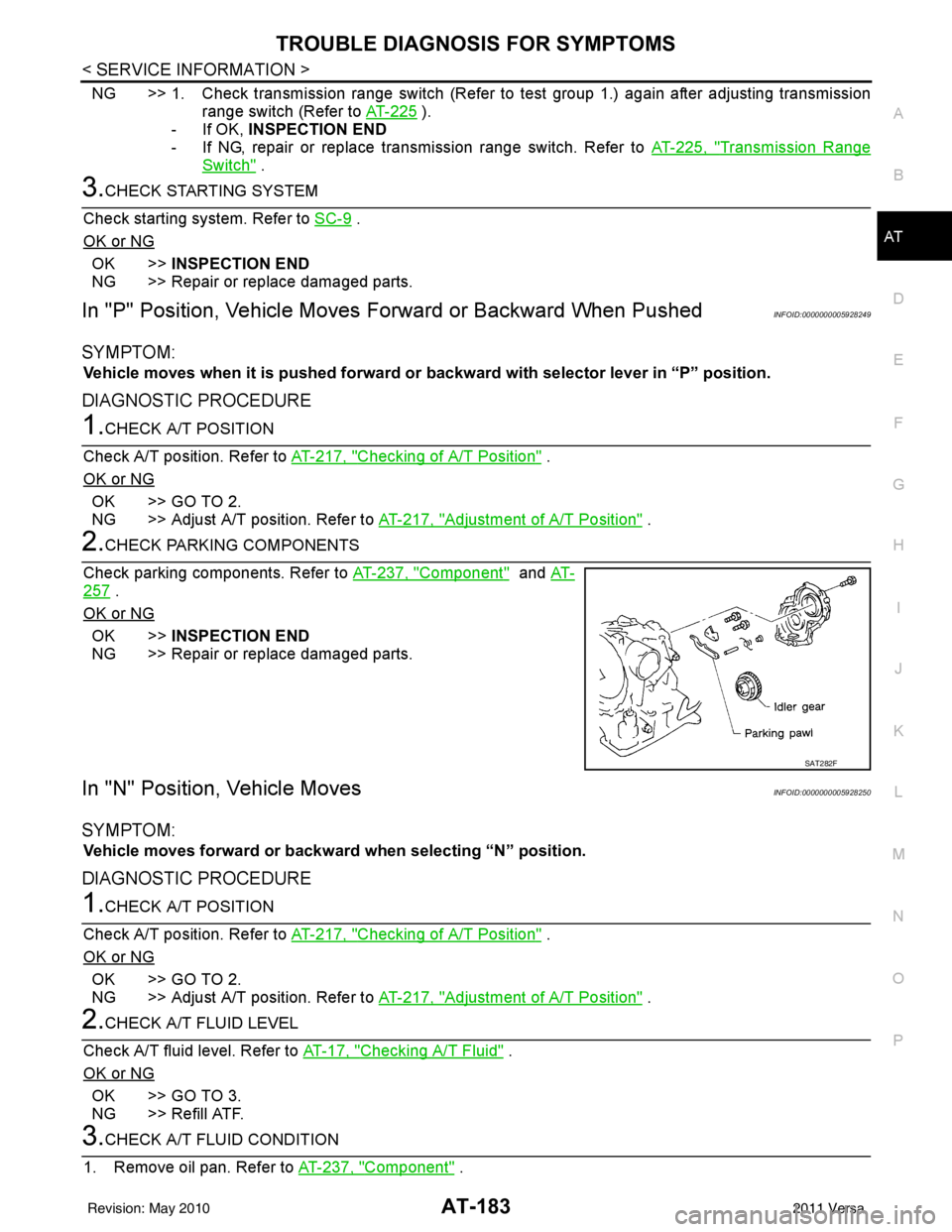
2.CHECK PARKING COMPONENTS
Check parking components. Refer to AT-237, "
Component" and AT-
257 .
OK or NG
OK >> INSPECTION END
NG >> Repair or replace damaged parts.
In "N" Position, Vehicle MovesINFOID:0000000005928250
SYMPTOM:
Vehicle moves forward or backwar d when selecting “N” position.
DIAGNOSTIC PROCEDURE
1.CHECK A/T POSITION
Check A/T position. Refer to AT-217, "
Checking of A/T Position" .
OK or NG
OK >> GO TO 2.
NG >> Adjust A/T position. Refer to AT-217, "
Adjustment of A/T Position" .
2.CHECK A/T FLUID LEVEL
Check A/T fluid level. Refer to AT-17, "
Checking A/T Fluid" .
OK or NG
OK >> GO TO 3.
NG >> Refill ATF.
3.CHECK A/T FLUID CONDITION
1. Remove oil pan. Refer to AT-237, "
Component" .
SAT282F
Revision: May 2010 2011 Versa