2011 NISSAN TIIDA p0420
[x] Cancel search: p0420Page 1298 of 3787
EC-4
DTC Logic ..............................................................249
Wiring Diagram ......................................................250
Diagnosis Procedure .............................................250
Component Inspection ...........................................252
P0222, P0223 TP SENSOR .............................253
Description ........................................................... ..253
DTC Logic ..............................................................253
Wiring Diagram ......................................................254
Diagnosis Procedure .............................................254
Component Inspection ...........................................256
Special Repair Requirement ..................................256
P0300, P0301, P0302, P0303, P0304 MIS-
FIRE ................................................................ .
257
DTC Logic ............................................................ ..257
Diagnosis Procedure .............................................258
P0327, P0328 KS .............................................263
Description ........................................................... ..263
DTC Logic ..............................................................263
Wiring Diagram ......................................................264
Diagnosis Procedure .............................................264
Component Inspection ...........................................265
P0335 CKP SENSOR (POS) ...........................267
Description ........................................................... ..267
DTC Logic ..............................................................267
Wiring Diagram ......................................................268
Diagnosis Procedure .............................................269
Component Inspection ...........................................271
P0340 CMP SENSOR (PHASE) ......................272
Description ........................................................... ..272
DTC Logic ..............................................................272
Wiring Diagram ......................................................274
Diagnosis Procedure .............................................274
Component Inspection ...........................................276
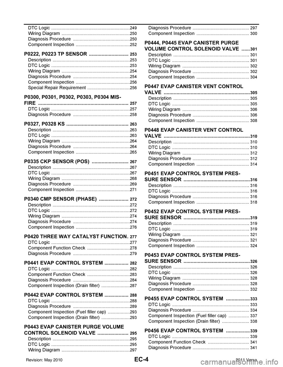
P0420 THREE WAY CATALYST FUNCTION .277
DTC Logic ..............................................................277
Component Function Check ..................................278
Diagnosis Procedure .............................................279
P0441 EVAP CONTROL SYSTEM ..................282
DTC Logic ............................................................ ..282
Component Function Check ..................................283
Diagnosis Procedure .............................................284
Component Inspection (Drain filter) .......................287
P0442 EVAP CONTROL SYSTEM ..................288
DTC Logic ............................................................ ..288
Diagnosis Procedure .............................................289
Component Inspection (Fuel filler cap) ..................293
Component Inspection (Drain filter) .......................293
P0443 EVAP CANISTER PURGE VOLUME
CONTROL SOLENOID VALVE .......................
295
Description ........................................................... ..295
DTC Logic ..............................................................295
Wiring Diagram ......................................................297
Diagnosis Procedure ............................................ .297
Component Inspection ..........................................300
P0444, P0445 EVAP CANISTER PURGE
VOLUME CONTROL SOLENOID VALVE .......
301
Description ........................................................... .301
DTC Logic .............................................................301
Wiring Diagram .....................................................302
Diagnosis Procedure .............................................302
Component Inspection ..........................................304
P0447 EVAP CANISTER VENT CONTROL
VALVE ..............................................................
305
Description ........................................................... .305
DTC Logic .............................................................305
Wiring Diagram .....................................................306
Diagnosis Procedure .............................................306
Component Inspection ..........................................308
P0448 EVAP CANISTER VENT CONTROL
VALVE ..............................................................
310
Description ........................................................... .310
DTC Logic .............................................................310
Wiring Diagram .....................................................312
Diagnosis Procedure .............................................312
Component Inspection ..........................................314
P0451 EVAP CONTROL SYSTEM PRES-
SURE SENSOR ................................................
316
Description ........................................................... .316
DTC Logic .............................................................316
Diagnosis Procedure .............................................316
Component Inspection ..........................................318
P0452 EVAP CONTROL SYSTEM PRES-
SURE SENSOR ................................................
319
Description ........................................................... .319
DTC Logic .............................................................319
Wiring Diagram .....................................................321
Diagnosis Procedure .............................................321
Component Inspection ..........................................324
P0453 EVAP CONTROL SYSTEM PRES-
SURE SENSOR ................................................
326
Description ........................................................... .326
DTC Logic .............................................................326
Wiring Diagram .....................................................328
Diagnosis Procedure .............................................328
Component Inspection ..........................................332
P0455 EVAP CONTROL SYSTEM ..................333
DTC Logic .............................................................333
Diagnosis Procedure .............................................334
Component Inspection (Fuel filler cap) .................337
Component Inspection (Drain filter) ......................338
P0456 EVAP CONTROL SYSTEM ..................339
DTC Logic .............................................................339
Component Function Check .................................341
Diagnosis Procedure .............................................341
Revision: May 2010 2011 Versa
Page 1301 of 3787
EC-7
C
DE
F
G H
I
J
K L
M
EC A
N
O P
Description ..........................................................
..
492
PRECAUTION ............................................493
PRECAUTIONS .............................................. ..493
Precaution for Supplemental Restraint System
(SRS) "AIR BAG" and "SEAT BELT PRE-TEN-
SIONER" ............................................................. ..
493
Precaution for Procedure without Cowl Top Cover ..493
On Board Diagnosis (OBD) System of Engine and
A/T .........................................................................
493
General Precautions .............................................494
PREPARATION .........................................497
PREPARATION .............................................. ..497
Special Service Tools .......................................... ..497
Commercial Service Tools ....................................497
ON-VEHICLE MAINTENANCE ..................499
FUEL PRESSURE .......................................... ..499
Inspection ............................................................ ..499
EVAP LEAK CHECK ........................................501
Inspection ............................................................ ..501
SERVICE DATA AND SPECIFICATIONS
(SDS) ......... ................................. ................
503
SERVICE DATA AND SPECIFICATIONS
(SDS) .............................................................. ..
503
Idle Speed ........................................................... ..503
Ignition Timing .......................................................503
Calculated Load Value ..........................................503
Mass Air Flow Sensor ...........................................503
MR18DE
SERVICE INFORMATION .. .......................
504
INDEX FOR DTC ............................................ ..504
U0101-U1001 ...................................................... ..504
P0011-P0075 ........................................................504
P0101-P0128 ........................................................504
P0130-P0183 ........................................................505
P0222-P0420 ........................................................505
P0441-P0463 ........................................................506
P0500-P0643 ........................................................506
P0705-P0734 ........................................................507
P0740-P0840 ........................................................507
P0850-P1574 ........................................................508
P1610-P1615 ........................................................508
P1715-P1805 ........................................................508
P2100-P2A00 ........................................................509
PRECAUTIONS ................................................510
Precaution for Supplemental Restraint System
(SRS) "AIR BAG" and "SEAT BELT PRE-TEN-
SIONER" ............................................................. ..
510
Precaution Necessary for Steering Wheel Rota-
tion After Battery Disconnect ............................... ..
510
Precaution for Procedure without Cowl Top Cover ..511
On Board Diagnosis (OBD) System of Engine and
A/T, CVT ................................................................
511
Precaution .............................................................511
PREPARATION ...............................................515
Special Service Tool ..............................................515
Commercial Service Tool ......................................515
ENGINE CONTROL SYSTEM ........................517
Schematic ............................................................ ..517
Multiport Fuel Injection (MFI) System ....................517
Electronic Ignition (EI) System ..............................520
Fuel Cut Control (at No Load and High Engine
Speed) ...................................................................
520
AIR CONDITIONING CUT CONTROL ............522
Input/Output Signal Chart ......................................522
System Description ................................................522
AUTOMATIC SPEED CONTROL DEVICE
(ASCD) ............................................................
523
System Description ................................................523
Component Description .........................................524
CAN COMMUNICATION .................................525
System Description ................................................525
EVAPORATIVE EMISSION SYSTEM .............526
Description .............................................................526
Component Inspection ...........................................528
How to Detect Fuel Vapor Leakage .......................530
ON BOARD REFUELING VAPOR RECOV-
ERY (ORVR) ....................................................
532
System Description ................................................532
Diagnosis Procedure .............................................532
Component Inspection ...........................................535
POSITIVE CRANKCASE VENTILATION .......538
Description .............................................................538
Component Inspection ...........................................538
NVIS (NISSAN VEHICLE IMMOBILIZER SYS-
TEM-NATS) .....................................................
540
Description .............................................................540
ON BOARD DIAGNOSTIC (OBD) SYSTEM ..541
Introduction ............................................................541
Two Trip Detection Logic .......................................541
Emission-related Diagnostic Information ...............542
Malfunction Indicator Lamp (MIL) ..........................565
OBD System Operation Chart ...............................568
BASIC SERVICE PROCEDURE .....................574
Basic Inspection ....................................................574
Idle Speed and Ignition Timing Check ...................578
Procedure After Replacing ECM ...........................579
VIN Registration ....................................................580
Accelerator Pedal Released Position Learning .....580
Throttle Valve Closed Position Learning ...............580
Revision: May 2010 2011 Versa
Page 1304 of 3787

EC-10
CONSULT-III Reference Value in Data Monitor
Mode .................................................................... ..
741
On Board Diagnosis Logic .....................................741
DTC Confirmation Procedure ................................741
Overall Function Check .........................................743
Wiring Diagram ......................................................744
Diagnosis Procedure .............................................745
Component Inspection ...........................................747
Removal and Installation .......................................749
DTC P014C, P014D A/F SENSOR 1 ...............750
Component Description ....................................... ..750
CONSULT-III Reference Value in Data Monitor
Mode .................................................................... ..
750
On Board Diagnosis Logic .....................................750
DTC Confirmation Procedure ................................750
Wiring Diagram ......................................................753
Diagnosis Procedure .............................................754
Removal and Installation .......................................757
DTC P0171 FUEL INJECTION SYSTEM
FUNCTION .......................................................
758
On Board Diagnosis Logic ................................... ..758
DTC Confirmation Procedure ................................758
Wiring Diagram ......................................................760
Diagnosis Procedure .............................................761
DTC P0172 FUEL INJECTION SYSTEM
FUNCTION .......................................................
764
On Board Diagnosis Logic ................................... ..764
DTC Confirmation Procedure ................................764
Wiring Diagram ......................................................766
Diagnosis Procedure .............................................767
DTC P0181 FTT SENSOR ...............................770
Component Description ....................................... ..770
On Board Diagnosis Logic .....................................770
DTC Confirmation Procedure ................................770
Wiring Diagram ......................................................771
Diagnosis Procedure .............................................771
Component Inspection ...........................................773
Removal and Installation .......................................773
DTC P0182, P0183 FTT SENSOR ..................774
Component Description ....................................... ..774
On Board Diagnosis Logic .....................................774
DTC Confirmation Procedure ................................774
Wiring Diagram ......................................................775
Diagnosis Procedure .............................................775
Component Inspection ...........................................777
Removal and Installation .......................................777
DTC P0222, P0223 TP SENSOR ....................778
Component Description ....................................... ..778
CONSULT-III Reference Value in Data Monitor
Mode .................................................................... ..
778
On Board Diagnosis Logic .....................................778
DTC Confirmation Procedure ................................778
Wiring Diagram ......................................................779
Diagnosis Procedure .............................................780
Component Inspection ......................................... .782
Removal and Installation .......................................782
DTC P0300 - P0304 MULTIPLE CYLINDER
MISFIRE, NO. 1 - 4 CYLINDER MISFIRE ...... ..
783
On Board Diagnosis Logic ................................... .783
DTC Confirmation Procedure ................................783
Diagnosis Procedure .............................................784
DTC P0327, P0328 KS .....................................789
Component Description ....................................... .789
On Board Diagnosis Logic ....................................789
DTC Confirmation Procedure ................................789
Wiring Diagram .....................................................790
Diagnosis Procedure .............................................791
Component Inspection ..........................................792
Removal and Installation .......................................792
DTC P0335 CKP SENSOR (POS) .................. ..793
Component Description ....................................... .793
CONSULT-III Reference Value in Data Monitor
Mode .................................................................... .
793
On Board Diagnosis Logic ....................................793
DTC Confirmation Procedure ................................793
Wiring Diagram .....................................................794
Diagnosis Procedure .............................................795
Component Inspection ..........................................798
Removal and Installation .......................................798
DTC P0340 CMP SENSOR (PHASE) ............ ..799
Component Description ....................................... .799
CONSULT-III Reference Value in Data Monitor
Mode .................................................................... .
799
On Board Diagnosis Logic ....................................799
DTC Confirmation Procedure ................................799
Wiring Diagram .....................................................800
Diagnosis Procedure .............................................801
Component Inspection ..........................................803
Removal and Installation .......................................804
DTC P0420 THREE WAY CATALYST FUNC-
TION ................................................................ ..
805
On Board Diagnosis Logic ................................... .805
DTC Confirmation Procedure ................................805
Overall Function Check .........................................805
Diagnosis Procedure .............................................806
DTC P0441 EVAP CONTROL SYSTEM ..........810
System Description .............................................. .810
On Board Diagnosis Logic ....................................810
DTC Confirmation Procedure ................................810
Overall Function Check .........................................811
Diagnosis Procedure .............................................811
Component Inspection ..........................................814
DTC P0442 EVAP CONTROL SYSTEM ..........815
On Board Diagnosis Logic ................................... .815
DTC Confirmation Procedure ................................816
Diagnosis Procedure .............................................816
Component Inspection ..........................................821
Revision: May 2010 2011 Versa
Page 1323 of 3787

HOW TO SET SRT CODEEC-29
< BASIC INSPECTION > [HR16DE]
C
D
E
F
G H
I
J
K L
M A
EC
NP
O
HOW TO SET SRT CODE
DescriptionINFOID:0000000006314657
OUTLINE
In order to set all SRTs, the self-diagnoses as in
the “SRT ITEM” table must have been performed at least
once. Each diagnosis may require actual driving for a long period of time under various conditions.
SRT ITEM
The table below shows required self-diagnostic items to set the SRT to “CMPLT”.
• *1: Though displayed on the CONSULT-III screen, “HO2S HTR” is not SRT item.
• *2: If completion of several SRTs is required, per form driving patterns (DTC confirmation procedure), one by
one based on the priority for models with CONSULT-III.
SRT SERVICE PROCEDURE
If a vehicle has failed the state emissions inspection due to one or more SRT items indicating “INCMP”, review
the flowchart diagnostic sequence, referring to the following flowchart.
SRT item*1
(CONSULT-III indication) Performance
Priority*2Required self-diagnostic items to set the SRT to “CMPLT” Corresponding
DTC No.
CATALYST 2 Three way catalyst function P0420
EVAP SYSTEM 2 EVAP control system purge flow monitoring P0441
1 EVAP control system P0442
2 EVAP control system P0456
HO2S 2 Air fuel ratio (A/F) sensor 1 P0133
Heated oxygen sensor 2 P0137
Heated oxygen sensor 2 P0138
Heated oxygen sensor 2 P0139
EGR/VVT SYSTEM 3 Intake value timing control function P0011
Revision: May 2010 2011 Versa
Page 1571 of 3787

P0420 THREE WAY CATALYST FUNCTIONEC-277
< COMPONENT DIAGNOSIS > [HR16DE]
C
D
E
F
G H
I
J
K L
M A
EC
NP
O
P0420 THREE WAY CATALYST FUNCTION
DTC LogicINFOID:0000000005929949
DTC DETECTION LOGIC
The ECM monitors the switching frequency ratio of air fuel ratio (A/F)
sensor 1 and heated oxygen sensor 2.
A three way catalyst (manifold) with high oxygen storage capacity
will indicate a low switching frequency of heated oxygen sensor 2.
As oxygen storage capacity decreases, the heated oxygen sensor 2
switching frequency will increase.
When the frequency ratio of A/F sensor 1 and heated oxygen sensor
2 approaches a specified limit value, the three way catalyst (mani-
fold) malfunction is diagnosed.
DTC CONFIRMATION PROCEDURE
1.INSPECTION START
Do you have CONSULT-III?
Do you have CONSULT-III?
YES >> GO TO 2.
NO >> GO TO 7.
2.PRECONDITIONING
If DTC Confirmation Procedure has been previously conducted, always turn ignition switch OFF and wait at
least 10 seconds before conducting the next test.
TESTING CONDITION:
Do not hold engine speed for more than the specified minutes below.
>> GO TO 3.
3.PERFORM DTC CONFIRMATION PROCEDURE-I
With CONSULT-III
1. Turn ignition switch ON and select “DATA MONITOR” mode with CONSULT-III.
2. Start engine and warm it up to normal operating temperature.
3. Turn ignition switch OFF and wait at least 10 seconds.
4. Start engine and keep the engine speed between 3,500 and 4,000 rpm for at least 1 minute under no load.
5. Let engine idle for 1 minute.
6. Make sure that “COOLAN TEMP /S” indication is more than 70°C (158°F).
If not, warm up engine and go to next step w hen “COOLAN TEMP/S” indication reaches 70 °C (158° F).
7. Open engine hood.
8. Select “DTC & SRT CONFIRMATION” then “SRT WORK SUPPORT” mode with CONSULT-III.
9. Rev engine up to 2,000 to 3,000 rpm and hold it for 3 consecutive minutes then release the accelerator
pedal completely.
10. Check the indication of “CATALYST”.
Which is displayed on CONSULT-III screen?
SEF484YB
DTC No. Trouble diagnosis name DTC detecting conditionPossible cause
P0420 Catalyst system efficiency
below threshold • Three way catalyst (manifold) does not
operate properly.
• Three way catalyst (manifold) does not
have enough oxygen storage capacity. • Three way catalyst (manifold)
• Exhaust tube
• Intake air leaks
• Fuel injector
• Fuel injector leaks
• Spark plug
• Improper ignition timing
Revision: May 2010
2011 Versa
Page 1572 of 3787

EC-278
< COMPONENT DIAGNOSIS >[HR16DE]
P0420 THREE WAY CATALYST FUNCTION
CMPLT >> GO TO 6.
INCMP >> GO TO 4.
4.PERFORM DTC CONFIRMATION PROCEDURE-II
1. Wait 5 seconds at idle.
2. Rev engine up to 2,000 to 3,000 rpm and maintain it unt il “INCMP” of “CATALYST” changes to “CMPLT” (It
will take approximately 5 minutes).
Does the indication change to
“CMPLT”?
YES >> GO TO 6.
NO >> GO TO 5.
5.PERFORM DTC CONFIRMATION PROCEDURE AGAIN
1. Stop engine and cool it down to less than 70 °C (158° F).
2. Perform DTC CONFIRMATION PROCEDURE again.
>> GO TO 3.
6.PERFORM DTC CONFIRMATION PROCEDURE-III
Check 1st trip DTC.
Is 1st trip DTC detected?
YES >> Go to EC-279, "Diagnosis Procedure".
NO >> INSPECTION END
7.PERFORM COMPONENT FUNCTION CHECK
Perform component function check. Refer to EC-278, "
Component Function Check".
NOTE:
Use component function check to check the overall functi on of the three way catalyst (manifold). During this
check, a 1st trip DTC might not be confirmed.
Is the inspection result normal?
YES >> INSPECTION END
NO >> Go to EC-279, "
Diagnosis Procedure".
Component Function CheckINFOID:0000000005929950
1.PERFORM COMPONENT FUNCTION CHECK
Without CONSULT-III
1. Start engine and warm it up to normal operating temperature.
2. Turn ignition switch OFF and wait at least 10 seconds.
3. Start engine and keep the engine speed between 3,500 and 4,000 rpm for at least 1 minute under no load.
4. Let engine idle for 1 minute.
5. Open engine hood.
6. Check the voltage between ECM harness connector and ground under the following condition.
Is the inspection result normal?
YES >> INSPECTION END
NO >> Go to EC-279, "
Diagnosis Procedure".
ECM Ground Condition Voltage
Con-
nector Te r m i n a l
F11 50
(HO2S2 signal) GroundKeeping engine speed
at 2,500 rpm constant
under no load The voltage fluctuation cy-
cle takes more than 5 sec-
onds.
1 cycle: 0.6 - 1.0 → 0 - 0.3
→ 0.6 - 1.0
PBIB2996E
Revision: May 2010
2011 Versa
Page 1573 of 3787

P0420 THREE WAY CATALYST FUNCTIONEC-279
< COMPONENT DIAGNOSIS > [HR16DE]
C
D
E
F
G H
I
J
K L
M A
EC
NP
O
Diagnosis ProcedureINFOID:0000000005929951
1.CHECK EXHAUST SYSTEM
Visually check exhaust tubes and muffler for dent.
Is the inspection result normal?
YES >> GO TO 2.
NO >> Repair or replace.
2.CHECK EXHAUST GAS LEAK
1. Start engine and run it at idle.
2. Listen for an exhaust gas leak before the three way catalyst (manifold).
Is exhaust gas leak detected?
YES >> Repair or replace. Refer to EM-30, "Exploded View".
NO >> GO TO 3.
3.CHECK INTAKE AIR LEAK
Listen for an intake air leak after the mass air flow sensor.
Is intake air leak detected?
YES >> Repair or replace. Refer to EM-25, "Exploded View".
NO >> GO TO 4.
4.CHECK IDLE SPEED AND IGNITION TIMING
For procedure, refer to EC-24, "
IGNITION TIMING : Special Repair Requirement".
For specification, refer to EC-503, "
Idle Speed" and EC-503, "Ignition Timing".
Is the inspection result normal?
YES >> GO TO 5.
NO >> Follow the instruction of EC-20, "
BASIC INSPECTION : Special Repair Requirement".
5.CHECK FUEL INJECTOR
1. Stop engine and then turn ignition switch ON.
2. Check the voltage between ECM harness connector and ground.
Is the inspection result normal?
YES >> GO TO 6.
NO >> Perform EC-434, "
Diagnosis Procedure".
6.CHECK FUNCTION OF IGNITION COIL-I
CAUTION:
PBIB1216E
ECM Ground Voltage
Connector Terminal
F10 25
Ground Battery voltage
29
30
31
JMBIA2201GB
Revision: May 2010
2011 Versa
Page 1574 of 3787

EC-280
< COMPONENT DIAGNOSIS >[HR16DE]
P0420 THREE WAY CATALYST FUNCTION
Do the following procedure in the place where ventilation is good without the combustible.
1. Turn ignition switch OFF.
2. Remove fuel pump fuse in IPDM E/R to release fuel pressure.
NOTE:
Do not use CONSULT-III to release fuel pressure, or fuel pressure applies again during the following pro-
cedure.
3. Start engine.
4. After engine stalls, crank it two or three times to release all fuel pressure.
5. Turn ignition switch OFF.
6. Remove all ignition coil harness connectors to avoi d the electrical discharge from the ignition coils.
7. Remove ignition coil and spark plug of the cylinder to be checked.
8. Crank engine for 5 seconds or more to remove combustion gas in the cylinder.
9. Connect spark plug and harness connector to ignition coil.
10. Fix ignition coil using a rope etc. with gap of 13 - 17 mm (0.52 - 0.66 in) between the edge of the spark plug and grounded metal
portion as shown in the figure.
11. Crank engine for about 3 seconds, and check whether spark is generated between the spark plug and the grounded metal por-
tion.
CAUTION:
• During the operation, always stay 0.5 m (19.7 in) awayfrom the spark plug and the ignition coil. Be careful not to
get an electrical shock wh ile checking, because the elec-
trical discharge voltage becomes 20 kV or more.
• It might cause to damage the igni tion coil if the gap of more than 17 mm (0.66 in) is taken.
NOTE:
When the gap is less than 13 mm (0.52 in), the sp ark might be generated even if the coil is mal-
functioning.
Is the inspection result normal?
YES >> GO TO 10.
NO >> GO TO 7.
7.CHECK FUNCTION OF IGNITION COIL-II
1. Turn ignition switch OFF.
2. Disconnect spark plug and connect a known-good spark plug.
3. Crank engine for about 3 seconds, and recheck whether spark is generated between the spark plug and the grounded metal portion.
Is the inspection result normal?
YES >> GO TO 8.
NO >> Check ignition coil, power transistor and their circuits. Refer to EC-444, "
Diagnosis Procedure".
8.CHECK SPARK PLUG
Check the initial spark plug for fouling, etc.
Is the inspection result normal?
YES >> Replace spark plug(s) with standard type one(s). For spark plug type, refer to EM-112, "
Spark Plug".
NO >> Repair or clean spark plug. Then GO TO 9.
9.CHECK FUNCTION OF IGNITION COIL-III Spark should be generated.
JMBIA0066GB
Spark should be generated.
SEF156I
Revision: May 2010
2011 Versa