2011 NISSAN TIIDA drive axle
[x] Cancel search: drive axlePage 1 of 3787

-1
QUICK REFERENCE INDEX
AGENERAL INFORMATIONGIGeneral Information
BENGINEEMEngine Mechanical
LUEngine Lubrication System
COEngine Cooling System
ECEngine Control System
FLFuel System
EXExhaust System
ACCAccelerator Control System
CTRANSMISSION/
TRANSAXLECLClutch System
MTManual Transaxle
ATAutomatic Transaxle
CVTCVT
DDRIVELINE/AXLEFAXFront Axle
RAXRear Axle
ESUSPENSIONFSUFront Suspension
RSURear Suspension
WTRoad Wheels & Tires
FBRAKESBRBrake System
PBParking Brake System
BRCBrake Control System
GSTEERINGPSPower Steering System
STCSteering Control System
HRESTRAINTSSBSeat Belts
SRSSupplemental Restraint System (SRS)
IBODYBLBody, Lock & Security System
GWGlasses, Window System & Mirrors
RFRoof
EIExterior & Interior
IPInstrument Panel
SESeat
JAIR CONDITIONERMTCManual Air Conditioner
KELECTRICALSCStarting & Charging System
LTLighting System
DIDriver Information System
WWWiper, Washer & Horn
BCSBody Control System
LANLAN System
AVAudio Visual, Navigation & Telephone System
ACSAuto Cruise Control System
PGPower Supply, Ground & Circuit Elements
LMAINTENANCEMAMaintenance
Edition: May 2010
Revision: May 2010
Publication No. SM1E-1C11U0
B
D
© 2010 NISSAN NORTH AMERICA, INC.
All rights reserved. No part of this Service Manual may be reproduced or stored in a retrieval system, or transmitted in any
form, or by any means, electronic, mechanical, photo-copying, recording or otherwise, without the prior written permission
of Nissan North America Inc.
A
C
E
F
G
H
I
J
K
L
M
Page 21 of 3787

AT-4
Transmission Range Switch ..................................225
Output Speed Sensor ............................................227
Input Speed Sensor ...............................................228
Differential Side Oil Seal ........................................229
AIR BREATHER HOSE ...................................232
Removal and Installation ..................................... ..232
TRANSAXLE ASSEMBLY ..............................233
Removal and Installation ..................................... ..233
OVERHAUL .................................................... .237
Component .......................................................... ..237
Oil Channel ............................................................250
Location of Adjusting Shims, Needle Bearings and
Thrust Washers .....................................................
253
Location of Snap Rings .........................................255
DISASSEMBLY .............................................. .257
Disassembly ........................................................ ..257
REPAIR FOR COMPONENT PARTS ..............275
Manual Shaft ....................................................... ..275
Oil Pump ................................................................278
Control Valve Assembly ........................................281
Control Valve Upper Body .....................................290
Control Valve Lower Body ................................... ..294
Reverse Clutch ......................................................297
High Clutch ............................................................302
Forward and Overrun Clutches .............................307
Low & Reverse Brake ............................................314
Rear Internal Gear and Forward Clutch Hub .........318
Output Shaft, Output Gear, Idler Gear, Reduction
Pinion Gear and Bearing Retainer .........................
322
Band Servo Piston Assembly ................................331
Final Drive .............................................................337
ASSEMBLY .....................................................344
Assembly (1) ........................................................ ..344
Adjustment (1) (For HR16DE Engine Models) ..... .345
Adjustment (1) (For MR18DE Engine Models) .....349
Assembly (2) .........................................................355
Adjustment (2) .......................................................360
Assembly (3) .........................................................363
SERVICE DATA AND SPECIFICATIONS
(SDS) ................................................................
373
General Specification ........................................... .373
Vehicle Speed at Which Gear Shifting Occurs .....373
Vehicle Speed at When Lock-up Occurs/Releases
.
373
Stall Speed ............................................................374
Line Pressure ........................................................374
Adjusting shims, Needle Bearings, Thrust Wash-
ers and Snap Rings ..............................................
374
Control Valves .......................................................375
Accumulator ..........................................................376
Clutches and Brakes .............................................376
Final Drive .............................................................378
Planetary Carrier ...................................................378
Oil Pump ...............................................................378
Input Shaft .............................................................378
Reduction Pinion Gear ..........................................378
Band Servo ...........................................................378
Output Shaft ..........................................................379
Bearing Retainer ...................................................379
Total End Play ...................................................... .379
Reverse Clutch End Play ......................................379
Removal and Installation .......................................379
Shift Solenoid Valves ........................................... .379
Solenoid Valves ....................................................380
A/T Fluid Temperature Sensor ..............................380
Output Speed Sensor ...........................................380
Dropping Resistor .................................................380
Input Speed Sensor ..............................................380
Revision: May 2010 2011 Versa
Page 25 of 3787

AT-8
< SERVICE INFORMATION >
PRECAUTIONS
6. Perform a self-diagnosis check of all control units using CONSULT-III.
Precaution for On Board Diagnosis (OBD) System of A/T and EngineINFOID:0000000005928065
The ECM has an on board diagnostic system. It will light up the malfunction indicator lamp (MIL) to warn the
driver of a malfunction causing emission deterioration.
CAUTION:
• Be sure to turn the ignition switch OFF and disconnect battery negative cable from battery negative
terminal before any repair or inspection work. The open/short circuit of related switches, sensors,
solenoid valves, etc. will cause the MIL to light up.
• Be sure to connect and lock the connectors secure ly after work. A loose (unlocked) connector will
cause the MIL to light up due to an open circuit. (Be sure the connectors are free from water, grease,
dirt, bent terminals, etc.)
• Be sure to route and secure th e harnesses properly after work. Interference of the harness with a
bracket, etc. may cause the MIL to light up due to a short circuit.
• Be sure to erase the unnecessary malfunction informa tion (repairs completed) from the TCM and
ECM before returning the vehicle to the customer.
PrecautionINFOID:0000000005928066
•Before connecting or disconn ecting the TCM harness connec-
tor, turn ignition switch OF F and disconnect the battery cable
from the negative terminal. Failure to do so may damage the
TCM. Because battery voltage is applied to TCM even if igni-
tion switch is turned off.
• When connecting or disconnect ing pin connectors into or
from TCM, take care not to damage pin terminals (bend or
break).
Make sure that there are not any bends or breaks on TCM pin
terminal, when connecting pin connectors.
• Before replacing TCM, perform TCM input/output signal
inspection and make sure whether TCM functions properly or
not. (See page AT-75, "
TCM Terminal and Reference Value".)
• After performing each TROUBLE DIAGNOSIS, perform “DTC
(Diagnostic Trouble Code) Confirmation Procedure”.
The DTC should not be displ ayed in the “DTC Confirmation
Procedure” if the repair is completed.
• Before proceeding with disassembly, thoroughly clean the outside of the transaxle. It is important to prevent the internal parts from
becoming contaminated by dirt or other foreign matter.
• Disassembly should be done in a clean work area.
• Use lint-free cloth or towels for wiping parts clean. Common shop rags can leave fibers that could in terfere with the operation of the A/T.
• Place disassembled parts in order for easier and proper assembly.
• All parts should be carefully cleaned with a general purpose, non-flammable solvent before inspection or reassembly.
SEF289H
AAT470A
MEF040DA
Revision: May 2010 2011 Versa
Page 34 of 3787
A/T FLUIDAT-17
< SERVICE INFORMATION >
DE
F
G H
I
J
K L
M A
B
AT
N
O P
A/T FLUID
Checking A/T FluidINFOID:0000000005928070
1. Warm up engine.
2. Check for A/T fluid leakage.
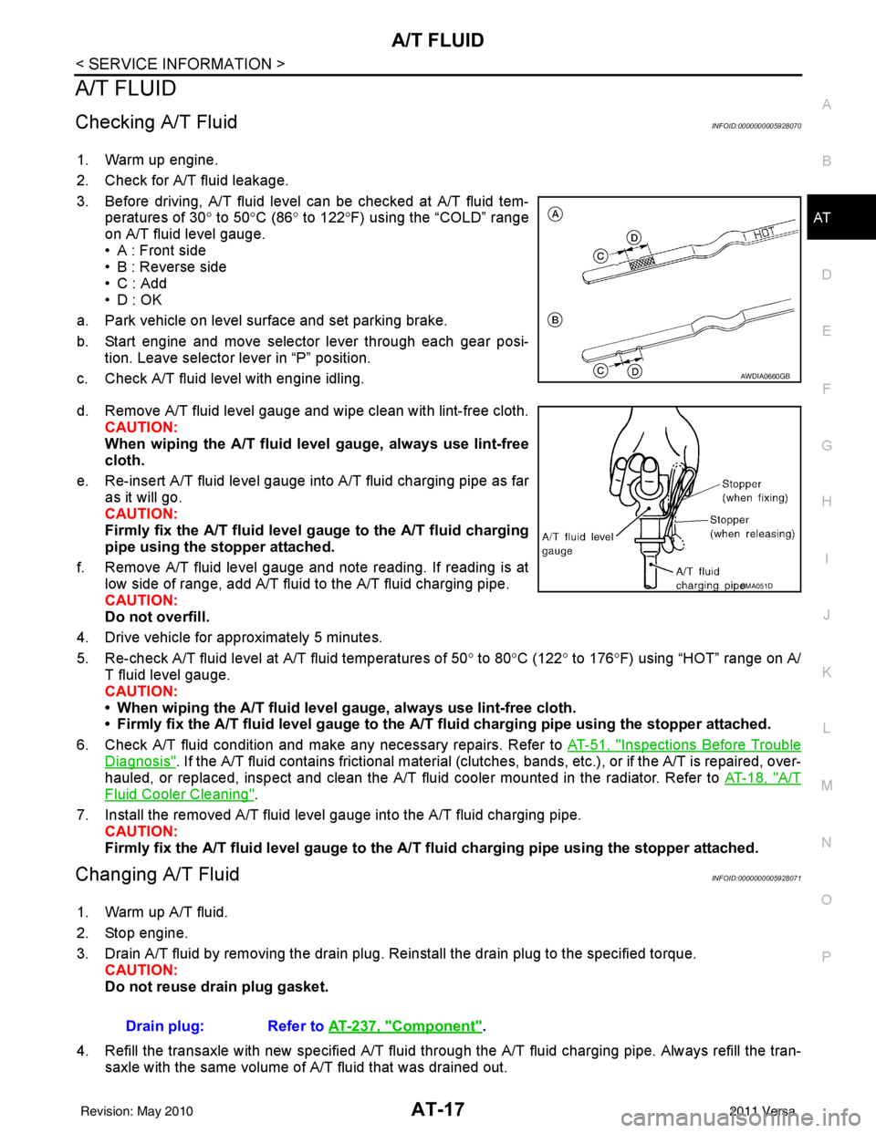
3. Before driving, A/T fluid level can be checked at A/T fluid tem- peratures of 30° to 50°C (86° to 122° F) using the “COLD” range
on A/T fluid level gauge.
• A : Front side
• B : Reverse side
•C : Add
• D : OK
a. Park vehicle on level surface and set parking brake.
b. Start engine and move selector lever through each gear posi- tion. Leave selector lever in “P” position.
c. Check A/T fluid level with engine idling.
d. Remove A/T fluid level gauge and wipe clean with lint-free cloth. CAUTION:
When wiping the A/T fluid l evel gauge, always use lint-free
cloth.
e. Re-insert A/T fluid level gauge into A/T fluid charging pipe as far as it will go.
CAUTION:
Firmly fix the A/T fluid level ga uge to the A/T fluid charging
pipe using the stopper attached.
f. Remove A/T fluid level gauge and note reading. If reading is at low side of range, add A/T fluid to the A/T fluid charging pipe.
CAUTION:
Do not overfill.
4. Drive vehicle for approximately 5 minutes.
5. Re-check A/T fluid level at A/T fluid temperatures of 50° to 80 °C (122° to 176°F) using “HOT” range on A/
T fluid level gauge.
CAUTION:
• When wiping the A/T fluid level gauge, always use lint-free cloth.
• Firmly fix the A/T fluid level ga uge to the A/T fluid charging pipe using the stopper attached.
6. Check A/T fluid condition and make any necessary repairs. Refer to AT-51, "
Inspections Before Trouble
Diagnosis". If the A/T fluid contains frictional material (clutches, bands, etc.), or if the A/T is repaired, over-
hauled, or replaced, inspect and clean the A/T fluid cooler mounted in the radiator. Refer to AT-18, "
A/T
Fluid Cooler Cleaning".
7. Install the removed A/T fluid level gauge into the A/T fluid charging pipe. CAUTION:
Firmly fix the A/T fluid level gaug e to the A/T fluid charging pipe using the stopper attached.
Changing A/T FluidINFOID:0000000005928071
1. Warm up A/T fluid.
2. Stop engine.
3. Drain A/T fluid by removing the drain plug. Re install the drain plug to the specified torque.
CAUTION:
Do not reuse drain plug gasket.
4. Refill the transaxle with new specified A/T fluid through the A/T fluid charging pipe. Always refill the tran- saxle with the same volume of A/T fluid that was drained out.
AWDIA0660GB
SMA051D
Drain plug: Refer to AT-237, "Component".
Revision: May 2010 2011 Versa
Page 46 of 3787
A/T CONTROL SYSTEMAT-29
< SERVICE INFORMATION >
DE
F
G H
I
J
K L
M A
B
AT
N
O P
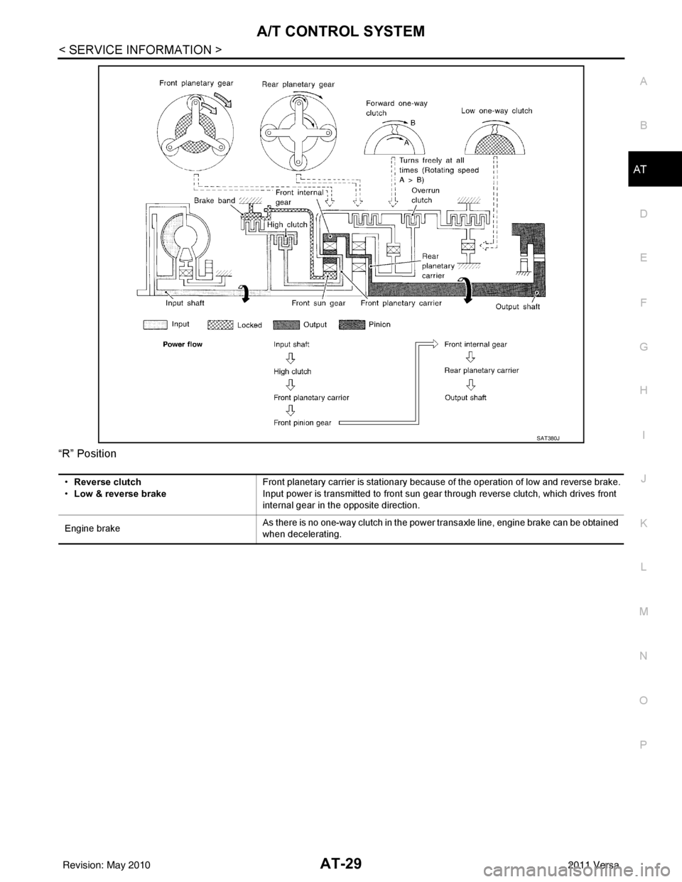
“R” Position
SAT380J
•
Reverse clutch
• Low & reverse brake Front planetary carrier is stationary because of the operation of low and reverse brake.
Input power is transmitted to front sun gear through reverse clutch, which drives front
internal gear in the opposite direction.
Engine brake As there is no one-way clutch in the power transaxle line, engine brake can be obtained
when decelerating.
Revision: May 2010
2011 Versa
Page 47 of 3787
AT-30
< SERVICE INFORMATION >
A/T CONTROL SYSTEM
TCM Function
INFOID:0000000005928075
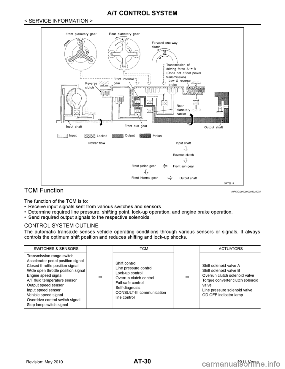
The function of the TCM is to:
• Receive input signals sent from various switches and sensors.
• Determine required line pressure, shifting poi nt, lock-up operation, and engine brake operation.
• Send required output signals to the respective solenoids.
CONTROL SYSTEM OUTLINE
The automatic transaxle senses vehicle operating conditions through various sensors or signals. It always
controls the optimum shift position and reduces shifting and lock-up shocks.
SAT381J
SWITCHES & SENSORS
⇒TCM
⇒ACTUATORS
Transmission range switch
Accelerator pedal position signal
Closed throttle position signal
Wide open throttle position signal
Engine speed signal
A/T fluid temperature sensor
Output speed sensor
Input speed sensor
Vehicle speed signal
Overdrive control switch signal
Stop lamp switch signal Shift control
Line pressure control
Lock-up control
Overrun clutch control
Fail-safe control
Self-diagnosis
CONSULT-III communication
line control
Shift solenoid valve A
Shift solenoid valve B
Overrun clutch solenoid valve
Torque converter clutch solenoid
valve
Line pressure solenoid valve
OD OFF indicator lamp
Revision: May 2010
2011 Versa
Page 91 of 3787

AT-74
< SERVICE INFORMATION >
TROUBLE DIAGNOSIS
OthersVehicle braked by
gear change from D
1
to D
2 . ON vehicle 1. A/T fluid level
AT- 1 7OFF vehicle2. Reverse clutch
AT- 2 9 73. Low & reverse brakeAT- 3 1 4
4. High clutchAT- 3 0 2
5. Low one-way clutchAT- 2 5 7
Vehicle braked by
gear change from D
2
to D
3 . ON vehicle 1. A/T fluid level
AT- 1 7OFF vehicle 2. Brake bandAT- 3 3 1
Vehicle braked by
gear change from D
3
to D
4 . ON vehicle 1. A/T fluid level
AT- 1 7OFF vehicle2. Overrun clutch
AT- 3 0 73. Forward one-way clutchAT- 3 1 8
4. Reverse clutchAT- 2 9 7
Maximum speed not
attained. Poor accel-
eration.ON vehicle1. A/T fluid level
AT- 1 7
2. Transmission range switch adjustmentAT- 2 2 5
3. Overdrive control switchAT- 1 7 1
4. Accelerator pedal position sensorEC-415
(HR16DE), EC-
982 (MR18DE)
5. Output speed sensor and vehicle speed signal AT- 1 0 0
, AT- 1 5 3
6. Shift solenoid valve A AT- 1 3 8
7. Shift solenoid valve BAT- 1 4 3
8. Control valve assemblyAT- 2 2 2
OFF vehicle9. Reverse clutch
AT- 2 9 7
10. High clutchAT- 3 0 2
11. Brake bandAT- 3 3 1
12. Low & reverse brakeAT- 3 1 4
13. Oil pumpAT- 2 7 8
14. Torque converterAT- 2 5 7
Transaxle noise in
“D”, “2”, “1” and “R”
positions.ON vehicle 1. A/T fluid level
AT- 1 7
OFF vehicle 2. Torque converterAT- 2 5 7
Engine brake does
not operate in “1” po-
sition.ON vehicle1. Transmission range switch adjustment
AT- 2 2 5
2. Control cable adjustmentAT- 2 1 7
3. Output speed sensor and vehicle speed signalAT- 1 0 0, AT- 1 5 3
4. Control valve assembly AT- 2 2 2
5. Overrun clutch solenoid valveAT- 1 4 8
OFF vehicle6. Overrun clutch
AT- 3 0 77. Low & reverse brakeAT- 3 1 4
ItemsSymptom Condition Diagnostic itemReference page
Revision: May 2010 2011 Versa
Page 155 of 3787
AT-138
< SERVICE INFORMATION >
P0750 SHIFT SOLENOID A
P0750 SHIFT SOLENOID A
DescriptionINFOID:0000000005928186
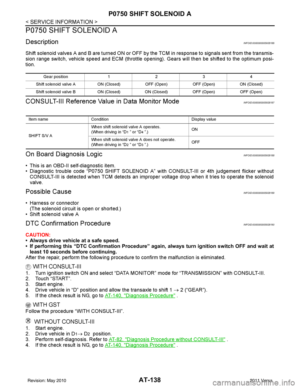
Shift solenoid valves A and B are turned ON or OFF by the TCM in response to signals sent from the transmis-
sion range switch, vehicle speed and ECM (throttle opening) . Gears will then be shifted to the optimum posi-
tion.
CONSULT-III Reference Value in Data Monitor ModeINFOID:0000000005928187
On Board Diagn osis LogicINFOID:0000000005928188
• This is an OBD-II self-diagnostic item.
• Diagnostic trouble code “P0750 SHIFT SOLENOID A” wi th CONSULT-III or 4th judgement flicker without
CONSULT-III is detected when TCM detects an improper voltage drop when it tries to operate the solenoid
valve.
Possible CauseINFOID:0000000005928189
• Harness or connector (The solenoid circuit is open or shorted.)
• Shift solenoid valve A
DTC Confirmation ProcedureINFOID:0000000005928190
CAUTION:
• Always drive vehicle at a safe speed.
• If performing this “DTC Confirmation Procedure” again, always turn ignition switch OFF and wait at
least 10 seconds before continuing.
After the repair, perform the following proc edure to confirm the malfunction is eliminated.
WITH CONSULT-III
1. Turn ignition switch ON and select “DATA MONI TOR” mode for “TRANSMISSION” with CONSULT-III.
2. Touch “START”.
3. Start engine.
4. Drive vehicle in “D” position and allow the transaxle to shift 1 → 2 (“GEAR”).
5. If the check result is NG, go to AT-140, "
Diagnosis Procedure" .
WITH GST
Follow the procedure “WITH CONSULT-III”.
WITHOUT CONSULT-III
1. Start engine.
2. Drive vehicle in D
1→ D2 position.
3. Perform self-diagnosis. Refer to AT-82, "
Diagnosis Procedure without CONSULT-III" .
4. If the check result is NG, go to AT-140, "
Diagnosis Procedure" .
Gea r p osit io n1234
Shift solenoid valve A ON (Closed)OFF (Open)OFF (Open)ON (Closed)
Shift solenoid valve B ON (Closed)ON (Closed) OFF (Open)OFF (Open)
Item name Condition Display value
SHIFT S/V A When shift solenoid valve A operates.
(When driving in “D
1 ” or “D4 ”.)
ON
When shift solenoid valve A does not operate.
(When driving in “D
2 ” or “D3 ”.) OFF
Revision: May 2010
2011 Versa