2011 NISSAN TIIDA RON 91
[x] Cancel search: RON 91Page 3084 of 3787

LT-52
< SERVICE INFORMATION >
TURN SIGNAL AND HAZARD WARNING LAMPS
• to combination meter terminal 27.
Ground is supplied
• to BCM terminal 67 and
• to combination meter terminals 21, 22 and 23
• through grounds M57 and M61.
When the remote keyless entry system is triggered by input from the keyfob, the BCM supplies power
• through BCM terminal 60
• to front combination lamp LH terminal 4 and
• to rear combination lamp LH terminal 6,
• through BCM terminal 61
• to front turn signal lamp RH terminal 4 and
• to rear combination lamp RH terminal 6.
Ground is supplied
• to front combination lamp LH and RH terminals 5
• through grounds E15 and E24,
• to rear combination lamp LH terminal 1
• through grounds B7 and B19,
• to rear combination lamp RH terminal 1
• through grounds B117, B132 (all m odels) and D402 (with hatchback).
The BCM also supplies input to combination meter via the CAN communication lines. This input is processed
by the unified meter control unit in combination meter, which in turn supplies ground to the left and right turn
signal indicator lamps.
With power and ground supplied, BCM controls flashing of hazard warning lamps when keyfob is used to acti-
vate remote keyless entry system.
COMBINATION SWITCH READING FUNCTION
Refer to BCS-4, "System Description" .
CAN Communication System DescriptionINFOID:0000000005929082
Refer to LAN-7, "System Description" .
Revision: May 2010 2011 Versa
Page 3090 of 3787
LT-58
< SERVICE INFORMATION >
TURN SIGNAL AND HAZARD WARNING LAMPS
3. Perform the preliminary check. Refer to LT-58, "Preliminary Check" .
4. Check symptom and repair or replace the cause of the malfunction.
5. Do turn signal and hazard warning lamps operate no rmally? If YES, GO TO 6. If NO, GO TO 4.
6. INSPECTION END
Preliminary CheckINFOID:0000000005929087
CHECK POWER SUPPLY AND GROUND CIRCUIT FOR BCM
Refer to BCS-16, "BCM Power Supply and Ground Circuit Inspection" .
CONSULT-III Function (BCM)INFOID:0000000005929088
Refer to BCS-17, "CONSULT-III Function (BCM)" .
Turn Signals Do Not OperateINFOID:0000000005929089
1.CHECK COMBINATION SWITCH (LIGHTING AND TURN SIGNAL SWITCH) INPUT SIGNAL
With CONSULT-III
1. Select “BCM” on CONSULT-III. Select “FLASHER” on “SELECT TEST ITEM” screen.
2. Select “DATA MONITOR” on “SELECT DIAG MODE ” screen. Make sure that “TURN SIGNAL R” and
“TURN SIGNAL L” turns ON-OFF linked with operation of lighting switch.
Without CONSULT-III
Refer to LT-65, "
Combination Switch Inspection" .
OK or NG
OK >> Replace the BCM. BCS-19, "Removal and Installation of BCM"
NG >> Check combination switch (lighting and turn signal switch). Refer to LT-65, "Combination Switch
Inspection" .
Front Turn Signal Lamp Does Not OperateINFOID:0000000005929090
1.CHECK BULB
Verify the bulb standard of each turn signal lamp is correct. Refer to LT-116, "
Exterior Lamp" .
OK or NG
OK >> GO TO 2.
NG >> Replace turn signal lamp bulb. Refer to LT-61, "
Bulb Replacement for Front Turn Signal Lamp" .
2.CHECK FRONT TURN SIGNAL LAMP CIRCUIT
1. Turn ignition switch OFF.
2. Disconnect BCM connector and front combination lamp LH or RH connector.
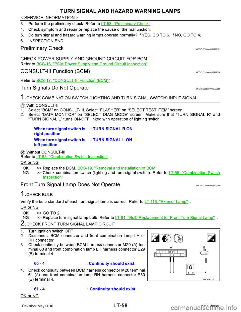
3. Check continuity between BCM harness connector M20 (A) ter- minal 60 and front combination lamp LH harness connector E29
(B) terminal 4.
4. Check continuity between BCM harness connector M20 terminal 61 (A) and front combination lamp RH harness connector E30
(B) terminal 4.
OK or NG
When turn signal switch is
right position : TURN SIGNAL R ON
When turn signal switch is
left position : TURN SIGNAL L ON
60 - 4
: Continuity should exist.
61 - 4 : Continuity should exist.
WKIA5612E
Revision: May 2010 2011 Versa
Page 3091 of 3787
TURN SIGNAL AND HAZARD WARNING LAMPSLT-59
< SERVICE INFORMATION >
C
DE
F
G H
I
J
L
M A
B
LT
N
O P
OK >> GO TO 3.
NG >> Repair harness or connector.
3.CHECK GROUND CIRCUIT
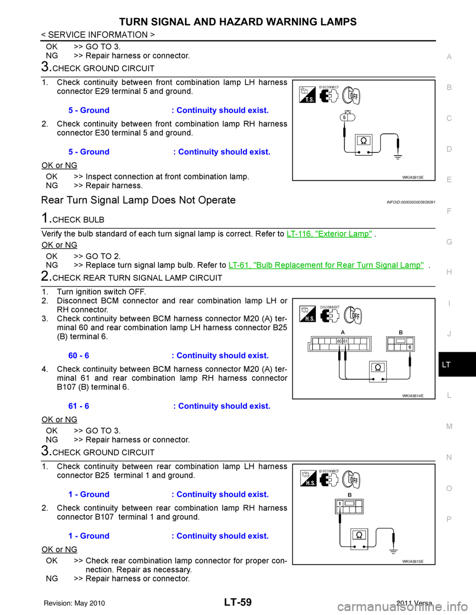
1. Check continuity between front combination lamp LH harness connector E29 terminal 5 and ground.
2. Check continuity between front combination lamp RH harness connector E30 terminal 5 and ground.
OK or NG
OK >> Inspect connection at front combination lamp.
NG >> Repair harness.
Rear Turn Signal Lamp Does Not OperateINFOID:0000000005929091
1.CHECK BULB
Verify the bulb standard of each turn signal lamp is correct. Refer to LT-116, "
Exterior Lamp" .
OK or NG
OK >> GO TO 2.
NG >> Replace turn signal lamp bulb. Refer to LT-61, "
Bulb Replacement for Rear Turn Signal Lamp" .
2.CHECK REAR TURN SIGNAL LAMP CIRCUIT
1. Turn ignition switch OFF.
2. Disconnect BCM connector and rear combination lamp LH or RH connector.
3. Check continuity between BCM harness connector M20 (A) ter- minal 60 and rear combination lamp LH harness connector B25
(B) terminal 6.
4. Check continuity between BCM harness connector M20 (A) ter- minal 61 and rear combination lamp RH harness connector
B107 (B) terminal 6.
OK or NG
OK >> GO TO 3.
NG >> Repair harness or connector.
3.CHECK GROUND CIRCUIT
1. Check continuity between rear combination lamp LH harness connector B25 terminal 1 and ground.
2. Check continuity between rear combination lamp RH harness connector B107 terminal 1 and ground.
OK or NG
OK >> Check rear combination lamp connector for proper con- nection. Repair as necessary.
NG >> Repair harness or connector. 5 - Ground : Continuity should exist.
5 - Ground : Continuity should exist.
WKIA5613E
60 - 6
: Continuity should exist.
61 - 6 : Continuity should exist.
WKIA5614E
1 - Ground: Continuity should exist.
1 - Ground : Continuity should exist.
WKIA5615E
Revision: May 2010 2011 Versa
Page 3093 of 3787
TURN SIGNAL AND HAZARD WARNING LAMPSLT-61
< SERVICE INFORMATION >
C
DE
F
G H
I
J
L
M A
B
LT
N
O P
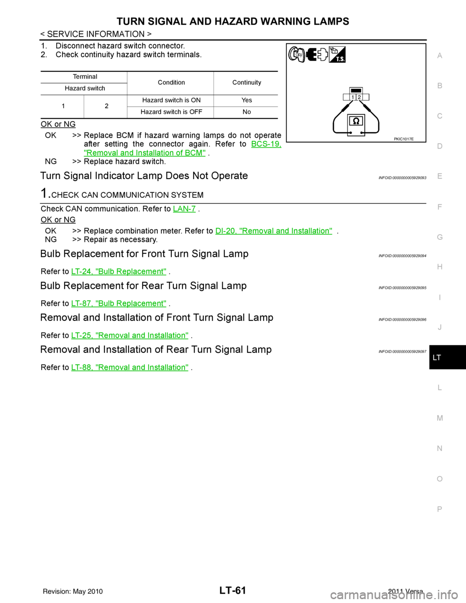
1. Disconnect hazard switch connector.
2. Check continuity hazard switch terminals.
OK or NG
OK >> Replace BCM if hazard warning lamps do not operate after setting the connector again. Refer to BCS-19,
"Removal and Installation of BCM" .
NG >> Replace hazard switch.
Turn Signal Indicator Lamp Does Not OperateINFOID:0000000005929093
1.CHECK CAN COMMUNICATION SYSTEM
Check CAN communication. Refer to LAN-7
.
OK or NG
OK >> Replace combination meter. Refer to DI-20, "Removal and Installation" .
NG >> Repair as necessary.
Bulb Replacement for Front Turn Signal LampINFOID:0000000005929094
Refer to LT-24, "Bulb Replacement" .
Bulb Replacement for Rear Turn Signal LampINFOID:0000000005929095
Refer to LT-87, "Bulb Replacement" .
Removal and Installation of Front Turn Signal LampINFOID:0000000005929096
Refer to LT-25, "Removal and Installation" .
Removal and Installation of Rear Turn Signal LampINFOID:0000000005929097
Refer to LT-88, "Removal and Installation" .
Te r m i n a l
Condition Continuity
Hazard switch
12 Hazard switch is ON
Yes
Hazard switch is OFF No
PKIC1017E
Revision: May 2010 2011 Versa
Page 3097 of 3787
COMBINATION SWITCHLT-65
< SERVICE INFORMATION >
C
DE
F
G H
I
J
L
M A
B
LT
N
O P
Terminal and Reference Value for BCMINFOID:0000000005929102
Refer to BCS-12, "Terminal and Reference Value for BCM" .
CONSULT-III Function (BCM)INFOID:0000000005929103
Refer to BCS-17, "CONSULT-III Function (BCM)" .
Combination Switch InspectionINFOID:0000000005929104
1.SYSTEM CHECK
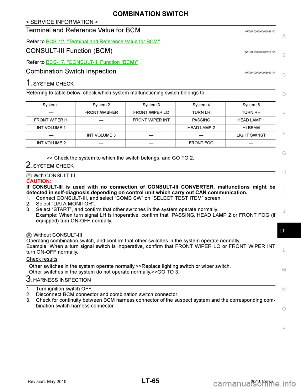
Referring to table below, check which system malfunctioning switch belongs to.
>> Check the system to which the switch belongs, and GO TO 2.
2.SYSTEM CHECK
With CONSULT-III
CAUTION:
If CONSULT-III is used with no connection of CONSULT-III CONVERTER, malfunctions might be
detected in self-diagnosis de pending on control unit which carry out CAN communication.
1. Connect CONSULT-III, and select “C OMB SW” on “SELECT TEST ITEM” screen.
2. Select “DATA MONITOR”.
3. Select “START”, and confirm that other switches in the system operate normally.
Example: When turn signal LH is inoperative, confi rm that PASSING, HEAD LAMP 2 or FRONT FOG (if
equipped) turn ON-OFF normally.
Without CONSULT-III
Operating combination switch, and confirm that other switches in the system operate normally.
Example: When a turn signal switch is inoperative, confirm that FRONT WIPER LO or FRONT WIPER INT
turn ON-OFF normally.
Check results
Other switches in the system operate normall y.>>Replace lighting switch or wiper switch.
Other switches in the system do not operate normally.>>GO TO 3.
3.HARNESS INSPECTION
1. Turn ignition switch OFF.
2. Disconnect BCM connector and combination switch connector.
3. Check for continuity between BCM harness connecto r of the suspect system and the corresponding com-
bination switch harness connector.
System 1 System 2System 3System 4System 5
— FRONT WASHER FRONT WIPER LO TURN LHTURN RH
FRONT WIPER HI —FRONT WIPER INT PASSINGHEAD LAMP 1
INT VOLUME 1 ——HEAD LAMP 2 HI BEAM
— INT VOLUME 3 ——LIGHT SW 1ST
INT VOLUME 2 ——FRONT FOG —
Revision: May 2010 2011 Versa
Page 3103 of 3787
STOP LAMPLT-71
< SERVICE INFORMATION >
C
DE
F
G H
I
J
L
M A
B
LT
N
O P
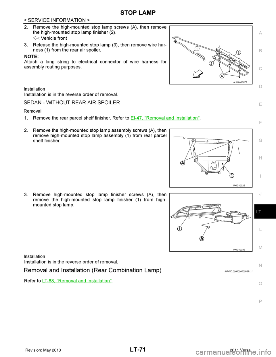
2. Remove the high-mounted stop lamp screws (A), then remove the high-mounted stop lamp finisher (2).
: Vehicle front
3. Release the high-mounted stop lamp (3), then remove wire har- ness (1) from the rear air spoiler.
NOTE:
Attach a long string to electrical connector of wire harness for
assembly routing purposes.
Installation
Installation is in the reverse order of removal.
SEDAN - WITHOUT REAR AIR SPOILER
Removal
1. Remove the rear parcel shelf finisher. Refer to EI-47, "Removal and Installation".
2. Remove the high-mounted stop lamp assembly screws (A), then remove high-mounted stop lamp assembly (1) from rear parcel
shelf finisher.
3. Remove high-mounted stop lamp finisher screws (A), then remove the high-mounted stop lamp finisher (1) from high-
mounted stop lamp.
Installation
Installation is in the reverse order of removal.
Removal and Installation (Rear Combination Lamp)INFOID:0000000005929111
Refer to LT-88, "Removal and Installation".
ALLIA0830ZZ
PKIC1022E
PKIC1023E
Revision: May 2010 2011 Versa
Page 3106 of 3787
LT-74
< SERVICE INFORMATION >
PARKING, LICENSE PLATE AND TAIL LAMPS
PARKING, LICENSE PLATE AND TAIL LAMPS
Component Parts and Harness Connector LocationINFOID:0000000005929115
System DescriptionINFOID:0000000005929116
The control of the parking, license plate and tail lamp operation is dependent upon the position of lighting
switch. When the lighting switch is placed in the 1ST position, the BCM (body cont rol module) receives input
signal requesting the parking, license plate and tail lamps to illuminate. This input signal is communicated to
the IPDM E/R (intelligent power distribution module engine room) via the CAN communication lines. The CPU
(central processing unit) located in the IPDM E/R contro ls the tail lamp relay coil. This relay, when energized,
directs power to parking, license plate and tail lamps, which then illuminate.
Power is supplied at all times
• to ignition relay located in IPDM E/R,
• to tail lamp relay located in IPDM E/R,
• through 15A fuse (No. 52, located in IPDM E/R) and
• through 20A fuse (No. 53, located in IPDM E/R)
• to the CPU located in the IPDM E/R,
• through 40A fusible link (letter g , located in fuse and fusible link block)
• to BCM terminal 70,
• through 10A fuse [No. 8, located in fuse block (J/B)],
• to BCM terminal 57.
With the ignition switch in the ON or START position, power is supplied
• through 10A fuse [No. 6, located in fuse block (J/B)]
• to BCM terminal 38,
• to ignition relay located in IPDM E/R and
• through the ignition relay
• to the CPU of the IPDM E/R.
With the ignition switch in the ACC or ON position, power is supplied
• through 10A fuse [No. 20, located in fuse block (J/B)]
• to BCM terminal 11.
Ground is supplied
• to BCM terminal 67
• through grounds M20 and M61,
• to IPDM E/R terminals 59 and 39
• through grounds E15 and E24.
OPERATION BY LIGHTING SWITCH
With the lighting switch in the 1ST or 2ND position, the BCM receives an input signal requesting parking,
license plate and tail lamps to illuminate. This input signal is communicated to the IPDM E/R via the CAN com-
munication lines. The CPU, located in the IPDM E/R, controls the tail lamp relay coil. When energized, the tail
lamp relay directs power
• through 10A fuse (No. 37, located in IPDM E/R),
• through IPDM E/R terminal 26
• to front combination lamp LH terminal 6, and
• through IPDM E/R terminal 27
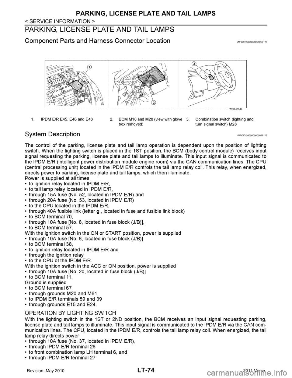
1. IPDM E/R E45, E46 and E48 2. BCM M18 and M20 (view with glove
box removed)3. Combination switch (lighting and
turn signal switch) M28
WKIA5554E
Revision: May 2010 2011 Versa
Page 3107 of 3787
PARKING, LICENSE PLATE AND TAIL LAMPS
LT-75
< SERVICE INFORMATION >
C
D E
F
G H
I
J
L
M A
B
LT
N
O P
• to front combination lamp RH terminal 6,
• through IPDM E/R terminal 28
• to rear combination lamp LH terminal 4 and
• to license plate lamp LH and RH terminal 1,
• through IPDM E/R terminal 29
• to rear combination lamp RH terminal 4.
Ground is supplied
• to front combination lamp LH and RH terminal 7
• through grounds E15 and E24,
• to rear combination lamp LH terminal 1 and
• to license plate lamp LH and RH terminal 2
• through grounds B7 and B19, and
• to rear combination lamp RH terminal 1
• through grounds B117, B132 (all models) and D402 (with hatchback).
With power and ground supplied, parking, license plate and tail lamps illuminate.
COMBINATION SWITCH READING FUNCTION
Refer to BCS-4, "System Description" .
EXTERIOR LAMP BATTERY SAVER CONTROL
When the combination switch (lighting and turn signal switch) is in the 1ST (or 2ND) position and the ignition
switch is turned from ON or ACC to OFF, t he battery saver control feature is activated.
Under this condition, the parking, license and tail lamps remain illumi nated for 5 minutes, then the parking,
license plate and tail lamps are turned off.
Exterior lamp battery saver control mode can be changed by the function setting of CONSULT-III.
CAN Communication System DescriptionINFOID:0000000005929117
Refer to LAN-7, "System Description" .
Revision: May 2010 2011 Versa