2011 NISSAN TIIDA RON 91
[x] Cancel search: RON 91Page 3076 of 3787

LT-44
< SERVICE INFORMATION >
FRONT FOG LAMP
Terminal and Reference Value for BCM
INFOID:0000000005929069
Refer to BCS-12, "Terminal and Reference Value for BCM" .
Terminal and Reference Value for IPDM E/RINFOID:0000000005929070
Refer to PG-25, "Terminal and Reference Value for IPDM E/R" .
LKWA0327E
Revision: May 2010 2011 Versa
Page 3077 of 3787
FRONT FOG LAMPLT-45
< SERVICE INFORMATION >
C
DE
F
G H
I
J
L
M A
B
LT
N
O P
How to Proceed with Trouble DiagnosisINFOID:0000000005929071
1. Confirm the symptom or customer complaint.
2. Understand operation description and function description. Refer to LT-41, "
System Description" .
3. Perform the Preliminary Check. Refer to LT-45, "
Preliminary Check" .
4. Check symptom and repair or replace the cause of the malfunction.
5. Do the front fog lamps operate normally? If YES, GO TO 6. If NO, GO TO 4.
6. INSPECTION END.
Preliminary CheckINFOID:0000000005929072
CHECK POWER SUPPLY AND GROUND CIRCUIT FOR BCM
Refer to BCS-16, "BCM Power Supply and Ground Circuit Inspection" .
CHECK POWER SUPPLY AND GROUND CIRCUIT FOR IPDM E/R
Refer to PG-27, "IPDM E/R Power/Ground Circuit Inspection" .
CONSULT-III Function (BCM)INFOID:0000000005929073
Refer to BCS-17, "CONSULT-III Function (BCM)" .
CONSULT-III Function (IPDM E/R)INFOID:0000000005929074
Refer to PG-18, "CONSULT-III Function (IPDM E/R)" .
Front Fog lamps Do Not Illuminate (Both Sides)INFOID:0000000005929075
1.INSPECT FOG LAMP FUSE
Inspect fog lamp 15A fuse No. 56 in IPDM E/R.
OK or NG
OK >> GO TO 2.
NG >> Repair harness.
2.CHECK COMBINATION SWITCH (LIGHTING AND TURN SIGNAL SWITCH) INPUT SIGNAL
1. Select “BCM” on CONSULT-III. Select “HEAD LAMP” on “SELECT TEST ITEM” screen.
2. Select “DATA MONITOR” on “SELECT DIAG MODE” screen. Make sure that “FR FOG SW” turns ON-
OFF linked with operation of fog lamp switch.
With CONSULT-III
Select “BCM” on CONSULT-III. With “HEAD LAMP” data monitor, make sure “FR FOG SW” turns ON-OFF
linked with operation of front fog lamp switch.
Without CONSULT-III
Refer to LT-65, "
Combination Switch Inspection" .
OK or NG
OK >> GO TO 3.
NG >> Check combination switch (lighting and turn signal switch). Refer to LT-65, "
Combination Switch
Inspection" .
3.FOG LAMP ACTIVE TEST
With CONSULT-III
1. Select “IPDM E/R” on CONSUL T-III. Select “ACTIVE TEST” on “SELECT DIAG MODE” screen.
2. Select “EXTERNAL LAMPS” on “SELECT TEST ITEM” screen.
3. Touch “FOG” screen.
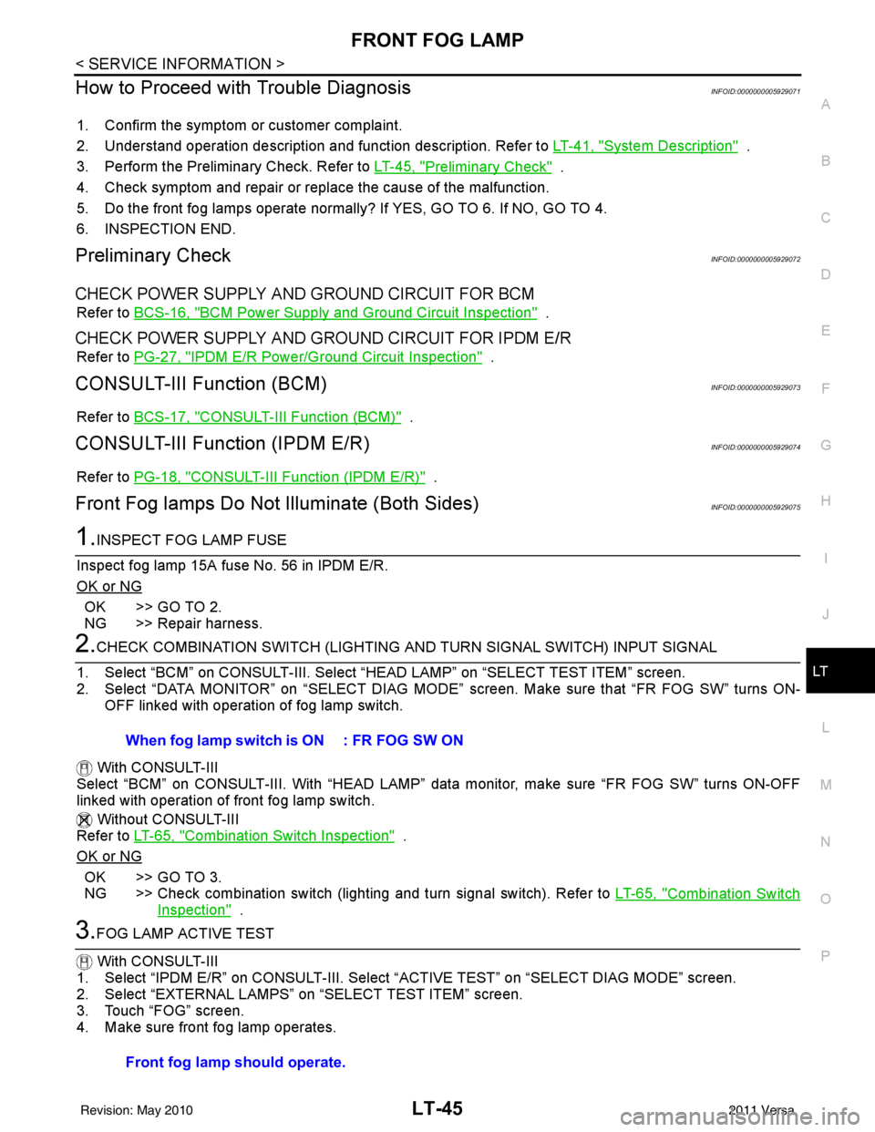
4. Make sure front fog lamp operates. When fog lamp switch is ON : FR FOG SW ON
Front fog lamp should operate.
Revision: May 2010
2011 Versa
Page 3078 of 3787
LT-46
< SERVICE INFORMATION >
FRONT FOG LAMP
Without CONSULT-III
1. Start auto active test. Refer to PG-20, "
Auto Active Test" .
2. Make sure front fog lamp operates.
OK or NG
OK >> GO TO 4.
NG >> GO TO 5.
4.CHECK IPDM E/R
1. Select “IPDM E/R” on CONSULT-III. Select “DATA MONITOR” on “SELECT DIAG MODE” screen.
2. Make sure “FR FOG REQ” turns ON when front fog lamp switch is in ON position.
OK or NG
OK >> Replace IPDM E/R. Refer to PG-28, "Removal and Installation of IPDM E/R" .
NG >> Replace BCM. Refer to BCS-19, "
Removal and Installation of BCM" .
5.CHECK FOG LAMP INPUT SIGNAL
With CONSULT-III
1. Turn ignition switch OFF.
2. Disconnect front fog lamp connector.
3. Select “IPDM E/R” on CONSULT-III, and sele ct “ACTIVE TEST” on “SELECT DIAG MODE” screen.
4. Select “EXTERNAL LAMPS” on “SELECT TEST ITEM” screen.
5. Touch “FOG” screen.
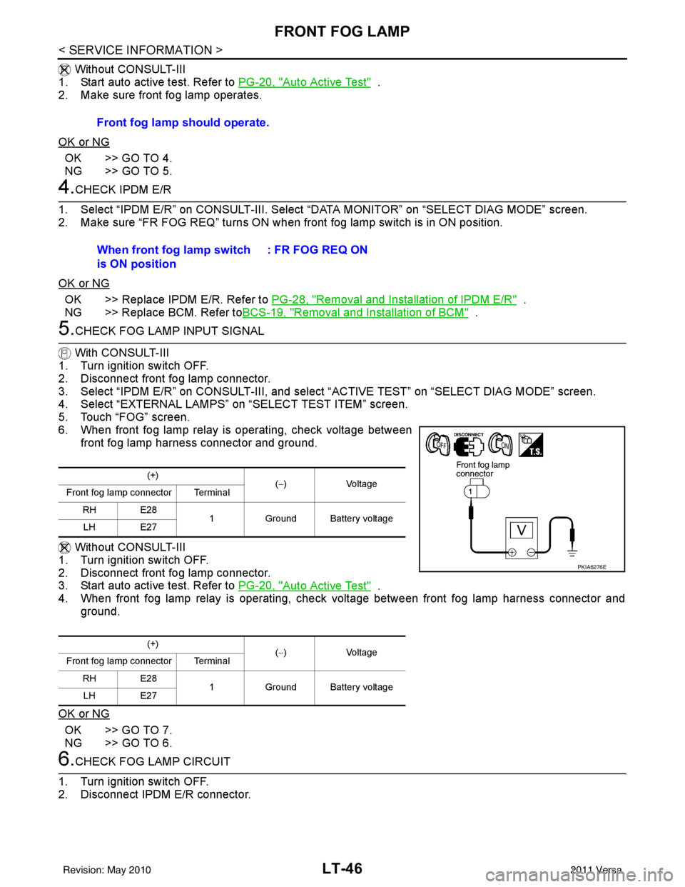
6. When front fog lamp relay is operating, check voltage between front fog lamp harness connector and ground.
Without CONSULT-III
1. Turn ignition switch OFF.
2. Disconnect front fog lamp connector.
3. Start auto active test. Refer to PG-20, "
Auto Active Test" .
4. When front fog lamp relay is operating, chec k voltage between front fog lamp harness connector and
ground.
OK or NG
OK >> GO TO 7.
NG >> GO TO 6.
6.CHECK FOG LAMP CIRCUIT
1. Turn ignition switch OFF.
2. Disconnect IPDM E/R connector. Front fog lamp should operate.
When front fog lamp switch
is ON position
: FR FOG REQ ON
(+)
(−) Voltage
Front fog lamp connector Terminal
RH E28 1Ground Battery voltage
LH E27
(+) (−) Voltage
Front fog lamp connector Terminal
RH E28 1Ground Battery voltage
LH E27
PKIA6276E
Revision: May 2010 2011 Versa
Page 3079 of 3787
FRONT FOG LAMPLT-47
< SERVICE INFORMATION >
C
DE
F
G H
I
J
L
M A
B
LT
N
O P
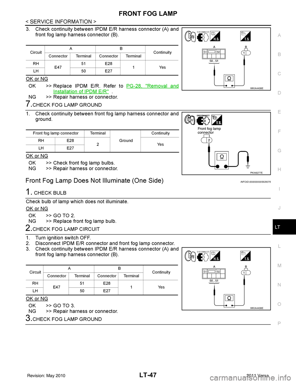
3. Check continuity between IPDM E/R harness connector (A) and front fog lamp harness connector (B).
OK or NG
OK >> Replace IPDM E/R. Refer to PG-28, "Removal and
Installation of IPDM E/R" .
NG >> Repair harness or connector.
7.CHECK FOG LAMP GROUND
1. Check continuity between front fog lamp harness connector and ground.
OK or NG
OK >> Check front fog lamp bulbs.
NG >> Repair harness or connector.
Front Fog Lamp Does Not Illuminate (One Side)INFOID:0000000005929076
1. CHECK BULB
Check bulb of lamp which does not illuminate.
OK or NG
OK >> GO TO 2.
NG >> Replace front fog lamp bulb.
2.CHECK FOG LAMP CIRCUIT
1. Turn ignition switch OFF.
2. Disconnect IPDM E/R connector and front fog lamp connector.
3. Check continuity between IPDM E/R harness connector (A) and front fog lamp harness connector (B).
OK or NG
OK >> GO TO 3.
NG >> Repair harness or connector.
3.CHECK FOG LAMP GROUND
Circuit AB
Continuity
Connector Terminal Connector Terminal
RH E47 51 E28
1Yes
LH 50 E27
WKIA4408E
Front fog lamp connector Terminal
Ground Continuity
RH E28
2Y es
LH E27
PKIA6277E
Circuit AB
Continuity
Connector Terminal Connector Terminal
RH E47 51 E28
1Yes
LH 50 E27
WKIA4408E
Revision: May 2010 2011 Versa
Page 3080 of 3787
LT-48
< SERVICE INFORMATION >
FRONT FOG LAMP
1. Check continuity between front fog lamp harness connector and
ground.
OK or NG
OK >> Replace IPDM E/R. Refer to PG-28, "Removal and
Installation of IPDM E/R" .
NG >> Repair harness or connector.
Aiming AdjustmentINFOID:0000000005929077
The front fog lamp is a semi-sealed beam type which uses a replaceable halogen bulb. Before performing
aiming adjustment, make sure of the following.
• Keep all tires inflated to correct pressure.
• Place vehicle on level surface.
• Set that there is no-load in vehicle other than the driv er (or equivalent weight placed in driver’s position).
Coolant, engine oil filled up to correct level and full fuel tank, spare tire, jack and tools are properly stowed.
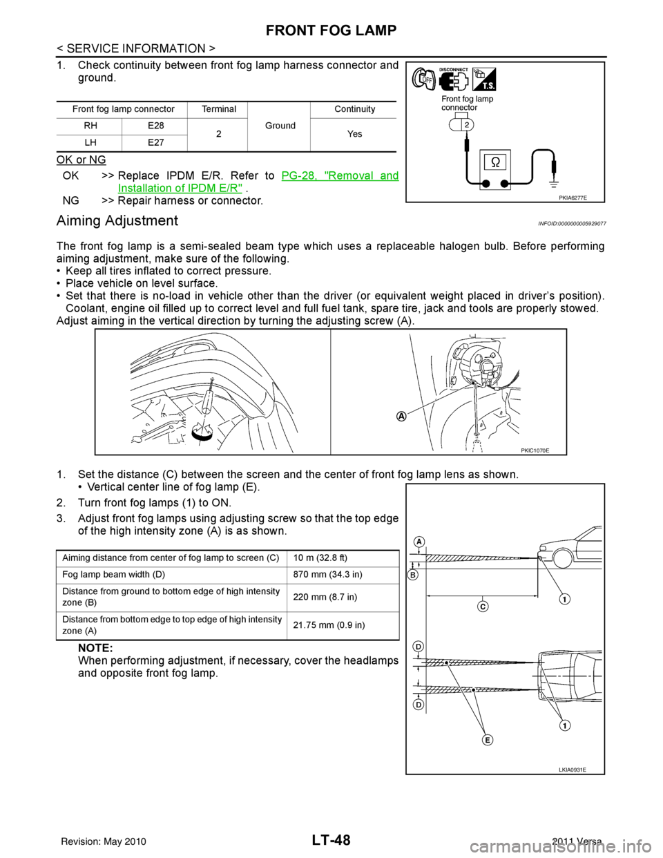
Adjust aiming in the vertical direct ion by turning the adjusting screw (A).
1. Set the distance (C) between the screen and the center of front fog lamp lens as shown. • Vertical center line of fog lamp (E).
2. Turn front fog lamps (1) to ON.
3. Adjust front fog lamps using adjusting screw so that the top edge of the high intensity zone (A) is as shown.
NOTE:
When performing adjustment, if necessary, cover the headlamps
and opposite front fog lamp.
Front fog lamp connector Terminal
Ground Continuity
RH E28
2Y es
LH E27
PKIA6277E
PKIC1070E
Aiming distance from center of fog lamp to screen (C) 10 m (32.8 ft)
Fog lamp beam width (D) 870 mm (34.3 in)
Distance from ground to bottom edge of high intensity
zone (B) 220 mm (8.7 in)
Distance from bottom edge to top edge of high intensity
zone (A) 21.75 mm (0.9 in)
LKIA0931E
Revision: May 2010
2011 Versa
Page 3081 of 3787
FRONT FOG LAMPLT-49
< SERVICE INFORMATION >
C
DE
F
G H
I
J
L
M A
B
LT
N
O P
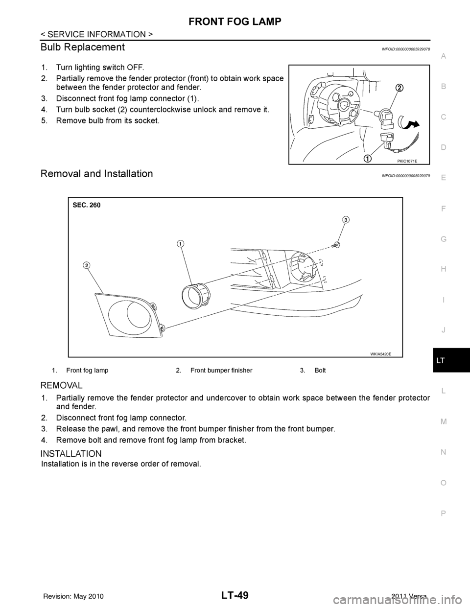
Bulb ReplacementINFOID:0000000005929078
1. Turn lighting switch OFF.
2. Partially remove the fender protec tor (front) to obtain work space
between the fender protector and fender.
3. Disconnect front fog lamp connector (1).
4. Turn bulb socket (2) counterclockwise unlock and remove it.
5. Remove bulb from its socket.
Removal and InstallationINFOID:0000000005929079
REMOVAL
1. Partially remove the fender protector and undercover to obtain work space between the fender protector
and fender.
2. Disconnect front fog lamp connector.
3. Release the pawl, and remove the front bumper finisher from the front bumper.
4. Remove bolt and remove front fog lamp from bracket.
INSTALLATION
Installation is in the reverse order of removal.
PKIC1071E
1. Front fog lamp 2. Front bumper finisher3. Bolt
WKIA5420E
Revision: May 2010 2011 Versa
Page 3082 of 3787
LT-50
< SERVICE INFORMATION >
TURN SIGNAL AND HAZARD WARNING LAMPS
TURN SIGNAL AND HAZARD WARNING LAMPS
Component Parts and Harn ess Connector LocationINFOID:0000000005929080
System DescriptionINFOID:0000000005929081
TURN SIGNAL OPERATION
Power is supplied at all times
• through 40A fusible link (letter g , located in the fuse and fusible link box)
• to BCM (body control module) terminal 70,
• through 10A fuse [No. 8, located in the fuse block (J/B)]
• to BCM terminal 57,
• through 10A fuse [No. 13, located in the fuse block (J/B)]
• to combination meter terminal 27.
With the ignition switch in the ON or START position, power is supplied
• through 10A fuse [No. 6, located in fuse block (J/B)]
• to BCM terminal 38,
• through 10A fuse [No. 3, located in fuse block (J/B)]
• to combination meter terminal 28.
With the ignition switch in the ACC or ON position, power is supplied
• through 10A fuse [No. 20, located in the fuse block (J/B)]
• to BCM terminal 11.
Ground is supplied
• to BCM terminal 67 and
• to combination meter terminals 21, 22 and 23
• through grounds M57 and M61.
LH Turn Signal Lamp
When the turn signal switch is moved to the left turn position, the BCM receives an input signal requesting left
turn signals to flash. The BCM then supplies power
• through BCM terminal 60
• to front combination lamp LH terminal 4 and
• to rear combination lamp LH terminal 6.
Ground is supplied
• to front combination lamp LH terminal 5
• through grounds E15 and E24,
• to rear combination lamp LH terminal 1
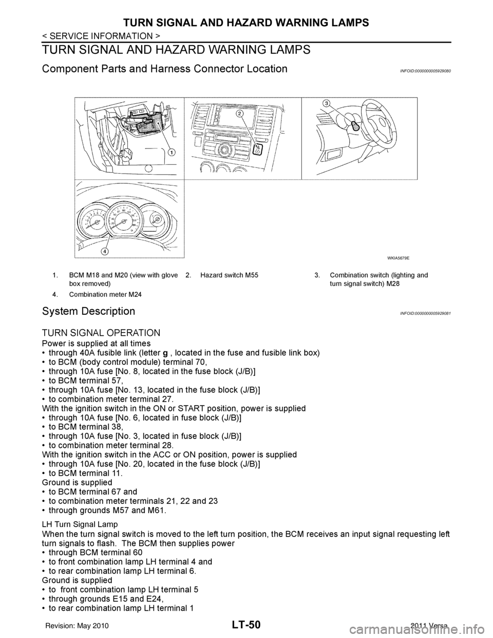
1. BCM M18 and M20 (view with glove
box removed) 2. Hazard switch M55 3. Combination switch (lighting and
turn signal switch) M28
4. Combination meter M24
WKIA5679E
Revision: May 2010 2011 Versa
Page 3083 of 3787

TURN SIGNAL AND HAZARD WARNING LAMPSLT-51
< SERVICE INFORMATION >
C
DE
F
G H
I
J
L
M A
B
LT
N
O P
• through grounds B7 and B19.
The BCM also sends a request, via the CAN communication lines, to the combination meter to flash the left
turn signal indicator. The unified meter control unit in the combination meter supplies ground to the \
left turn
signal indicator lamp and activates the audible turn signal indicator.
With power, ground and input supplied, the BCM controls the flashing of the turn signal lamps.
RH Turn Signal Lamp
When turn signal switch is moved to the right turn position, the BCM receives an input signal requesting right
turn signals to flash. The BCM then supplies power
• through BCM terminal 61
• to front combination lamp RH terminal 4 and
• to rear combination lamp RH terminal 6.
Ground is supplied
• to front combination lamp RH terminal 5
• through grounds E15 and E24,
• to rear combination lamp RH terminal 1
• through grounds B117, B132 (all models) and D402 (with hatchback).
The BCM also sends a request, via the CAN communication lines, to the combination meter to flash the right
turn signal indicator. The unified meter control unit in the combination meter supplies ground to the right turn
signal indicator lamp and activates the audible turn signal indicator.
With power, ground and input supplied, the BCM controls the flashing of the turn signal lamps.
HAZARD LAMP OPERATION
Power is supplied at all times
• through 40A fusible link (letter g , located in fuse, fusible link and relay box)
• to BCM terminal 70,
• through 10A fuse [No. 8, located in fuse block (J/B)]
• to BCM terminal 57,
• through 10A fuse [No. 13, located in fuse block (J/B)]
• to combination meter terminal 27.
Ground is supplied
• to hazard switch terminal 1,
• to BCM terminal 67, and
• to combination meter terminals 21, 22 and 23
• through grounds M57 and M61.
When hazard switch is depressed, ground is supplied
• through hazard switch terminal 2
• to BCM terminal 29.
BCM then supplies power
• to front combination lamp LH terminal 4 and
• to rear combination lamp LH terminal 6
• through BCM terminal 60,
• to front combination lamp RH terminal 4 and
• to rear combination lamp RH terminal 6
• through BCM terminal 61.
Ground is supplied
• to front combination lamp LH and RH terminal 5
• through grounds E15 and E24,
• to rear combination lamp LH terminal 1
• through grounds B7 and B19,
• to rear combination lamp RH terminal 1
• through grounds B117, B132 and D402 (hatchback).
The BCM also supplies input to combination meter ac ross the CAN communication lines. This input is pro-
cessed by unified meter control unit in combination mete r, which in turn supplies ground to the left and right
turn signal indicator lamps.
With power and input supplied, BCM controls flashing of hazard warning lamps.
REMOTE KEYLESS ENTRY SYSTEM OPERATION
Power is supplied at all times
• through 40A fusible link (letter g , located in fuse, fusible link and relay box)
• to BCM terminal 70,
• through 10A fuse [No. 13, located in fuse block (J/B)]
Revision: May 2010 2011 Versa