2011 NISSAN TIIDA RON 91
[x] Cancel search: RON 91Page 2800 of 3787
GW-46
< SERVICE INFORMATION >
FRONT DOOR GLASS AND REGULATOR
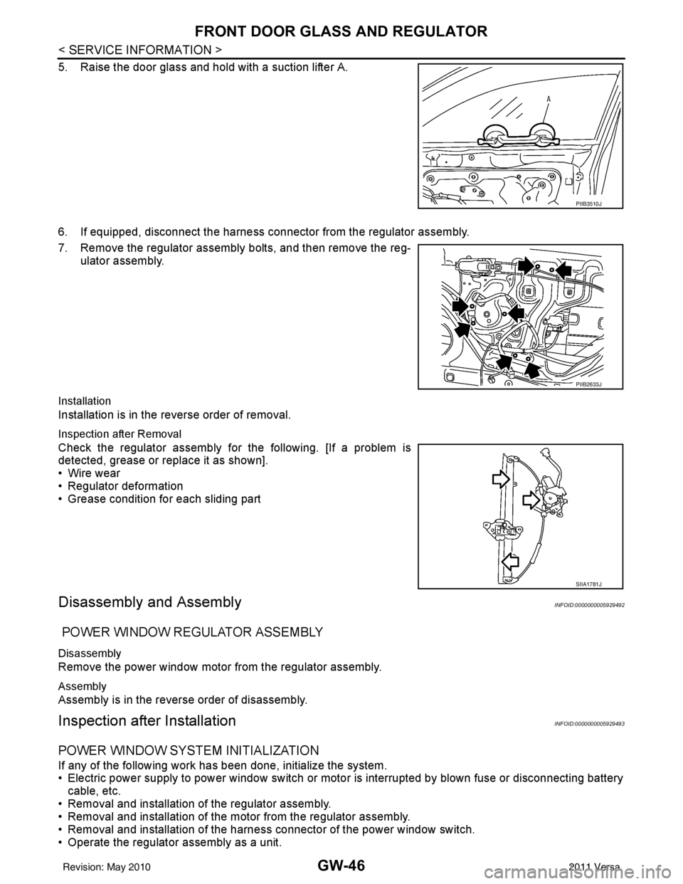
5. Raise the door glass and hold with a suction lifter A.
6. If equipped, disconnect the harness connector from the regulator assembly.
7. Remove the regulator assembly bolts, and then remove the reg-ulator assembly.
Installation
Installation is in the reverse order of removal.
Inspection after Removal
Check the regulator assembly fo r the following. [If a problem is
detected, grease or replace it as shown].
• Wire wear
• Regulator deformation
• Grease condition for each sliding part
Disassembly and AssemblyINFOID:0000000005929492
POWER WINDOW REGULATOR ASSEMBLY
Disassembly
Remove the power window motor from the regulator assembly.
Assembly
Assembly is in the reverse order of disassembly.
Inspection after InstallationINFOID:0000000005929493
POWER WINDOW SYSTEM INITIALIZATION
If any of the following work has been done, initialize the system.
• Electric power supply to power window switch or moto r is interrupted by blown fuse or disconnecting battery
cable, etc.
• Removal and installation of the regulator assembly.
• Removal and installation of the motor from the regulator assembly.
• Removal and installation of the harness connector of the power window switch.
• Operate the regulator assembly as a unit.
PIIB3510J
PIIB2633J
SIIA1781J
Revision: May 2010 2011 Versa
Page 2801 of 3787

FRONT DOOR GLASS AND REGULATORGW-47
< SERVICE INFORMATION >
C
DE
F
G H
J
K L
M A
B
GW
N
O P
• Removal and installation of the door glass.
• Removal and installation of the door glass run.
Initialization
After installing each component to the vehicle, follow the steps below.
1. Disconnect the battery negative c able or disconnect power window switch's harness connector tempo-
rarily, then reconnect after at least 1 minute.
2. Turn ignition switch ON.
3. Open the window to its full width by operating the power window switch. (Exclude this procedure if the window is already fully opened).
4. Move the power window switch in the up direction (auto close position) and hold. Keep holding the switch
even when window is completely closed, and then release after 4 seconds have passed.
5. Confirm window is now operating correctly. NOTE:
Initialization may be cancelled with continuous opening and closing operation. In this case, initialize the
system.
INSPECT THE FUNCTION OF THE ANTI-PINCH SYSTEM
1. Fully open the door glass.
2. Place a wooden piece (wooden hammer handle, etc.) near the fully closed position.
3. Carry out fully closing operation with auto up switch.
• Check that the glass reverses without pinching the w ooden piece, is lowered approx.150 mm (5.91 in) or for
2 seconds and then stops.
• The glass should not be raised with power window main switch while it is reversing or lowering.
CAUTION:
• Use care to avoid being pinched during the inspection. Do not u se a hand, etc. in place of the
wooden piece durin g the inspection.
• Check that auto up function is normal before inspection, following the system initialization.
FITTING INSPECTION
• Make sure the glass is securely fit into the glass run groove.
• Lower the glass slightly [approx. 10 to 20 mm (0.39 to 0.79 in)] and make sure the clearance to the sash is
parallel. If the clearance between the glass and sash is not parallel, loosen the regulator bolts, guide rail
bolts, and the glass and guide rail bolts to correct the glass position.
• Make sure the system is normal with raising and lowering the glass.
Revision: May 2010 2011 Versa
Page 2805 of 3787
REAR WINDOW DEFOGGERGW-51
< SERVICE INFORMATION >
C
DE
F
G H
J
K L
M A
B
GW
N
O P
REAR WINDOW DEFOGGER
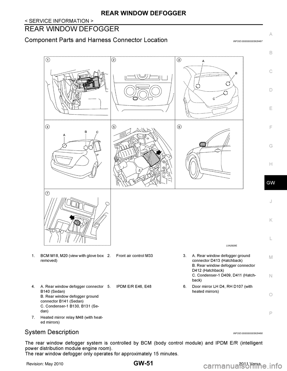
Component Parts and Har ness Connector LocationINFOID:0000000005929497
System DescriptionINFOID:0000000005929498
The rear window defogger system is controlled by BCM (body control module) and IPDM E/R (intelligent
power distribution module engine room).
The rear window defogger only operates for approximately 15 minutes.
1. BCM M18, M20 (view with glove box
removed) 2. Front air control M33 3. A. Rear window defogger ground
connector D413 (Hatchback)
B. Rear window defogger connector
D412 (Hatchback)
C. Condenser-1 D409, D411 (Hatch-
back)
4. A. Rear window defogger connector B140 (Sedan)
B. Rear window defogger ground
connector B141 (Sedan)
C. Condenser-1 B130, B131 (Se-
dan) 5. IPDM E/R E46, E48
6. Door mirror LH D4, RH D107 (with
heated mirrors)
7. Heated mirror relay M48 (with heat- ed mirrors)
LIIA2929E
Revision: May 2010 2011 Versa
Page 2806 of 3787

GW-52
< SERVICE INFORMATION >
REAR WINDOW DEFOGGER
Power is supplied at all times
• through 15A fuses (No. 46 and 47, located in the IPDM E/R)
• to rear window defogger relay
• through 10A fuse [No. 5 (with heated mirrors), located in the fuse block (J/B)]
• to heated mirror relay terminal 3
• through 40A fusible link (letter g , located in the fuse and fusible link box)
• to BCM terminal 70.
With the ignition switch turned to ON or START position, power is supplied
• through ignition relay
• to rear window defogger relay (located in the IPDM E/R)
• through 10A fuse [No. 6, located in the fuse block (J/B)]
• to BCM terminal 38.
Ground is supplied
• to BCM terminal 67 and
• to front air control terminal 8
• through body grounds M57 and M61
• to IPDM E/R terminals 39 and 59
• through body grounds E15 and E24.
When front air control (rear window defogger switch) is turned to ON, ground is supplied
• to BCM terminal 9
• through front air control terminal 3
• through front air control terminal 8
• through body grounds M57 and M61.
Then rear window defogger switch is illuminated.
Then BCM recognizes that rear window defogger switch is turned to ON.
Then it sends rear window defogger switch signals to IPDM E/R via CAN communication (CAN-H, CAN-L).
When IPDM E/R receives rear window defogger switch signals, ground is supplied
• to rear window defogger relay (located in the IPDM E/R)
• through IPDM E/R terminals 39 and 59
• through body grounds E15 and E24
Then rear window defogger relay is energized.
With power and ground supplied, rear window def ogger filaments heat and defog the rear window.
When rear window defogger relay is turned to ON (with heated mirrors), power is supplied
• through heated mirror relay terminal 5
• to door mirror (LH and RH) terminal 1.
Door mirror (LH and RH) is grounded through body grounds M57 and M61.
With power and ground supplied, rear window defogger filaments heat and defog the rear window and door
mirror filaments heat and defog the mirrors.
CAN Communication System DescriptionINFOID:0000000005929499
Refer to LAN-7, "System Description".
Revision: May 2010 2011 Versa
Page 2810 of 3787
GW-56
< SERVICE INFORMATION >
REAR WINDOW DEFOGGER
BCM Power Supply and Ground Circuit Inspection
INFOID:0000000005929506
Refer to BCS-16, "BCM Power Supply and Ground Circuit Inspection" .
Rear Window Defogger Swit ch Circuit InspectionINFOID:0000000005929507
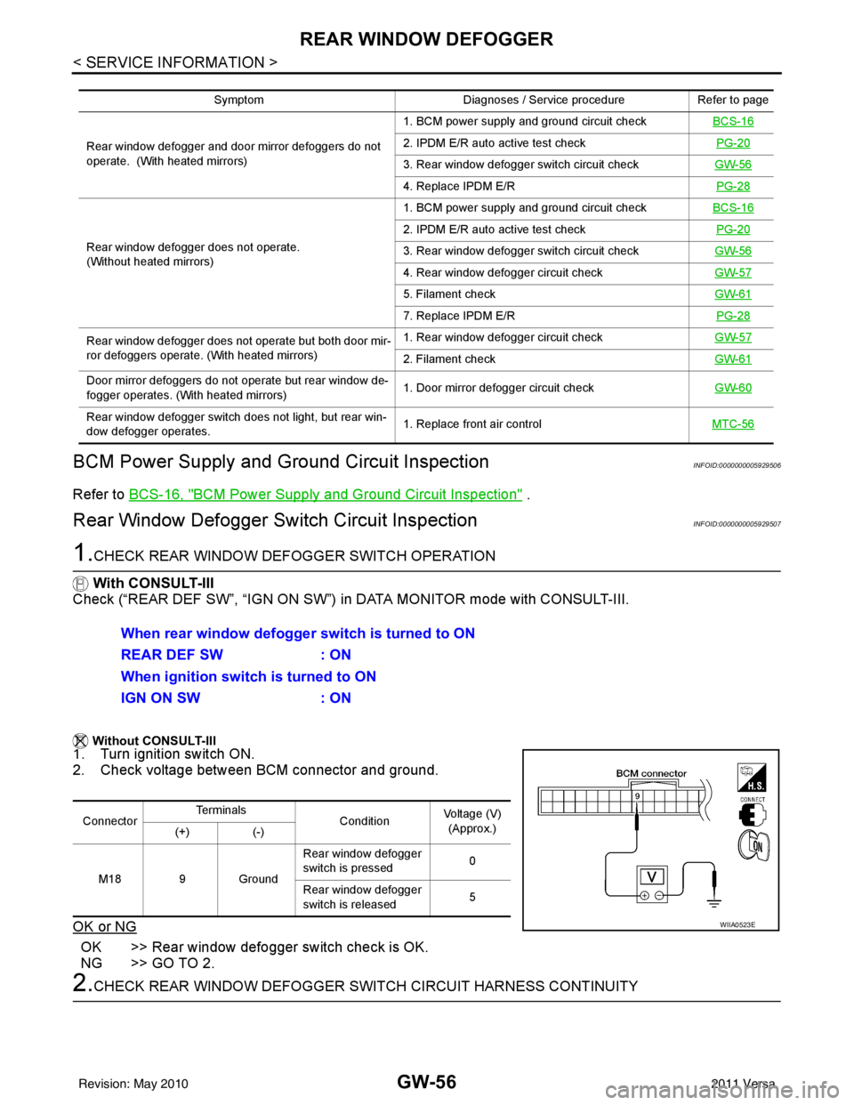
1.CHECK REAR WINDOW DEFOGGER SWITCH OPERATION
With CONSULT-III
Check (“REAR DEF SW”, “IGN ON SW”) in DATA MONITOR mode with CONSULT-III.
Without CONSULT-III
1. Turn ignition switch ON.
2. Check voltage between BCM connector and ground.
OK or NG
OK >> Rear window defogger switch check is OK.
NG >> GO TO 2.
2.CHECK REAR WINDOW DEFOGGER SWITCH CIRCUIT HARNESS CONTINUITY
Symptom Diagnoses / Service procedureRefer to page
Rear window defogger and door mirror defoggers do not
operate. (With heated mirrors) 1. BCM power supply and ground circuit check
BCS-16
2. IPDM E/R auto active test check PG-20
3. Rear window defogger switch circuit checkGW-56
4. Replace IPDM E/R PG-28
Rear window defogger does not operate.
(Without heated mirrors) 1. BCM power supply and ground circuit check
BCS-16
2. IPDM E/R auto active test check PG-20
3. Rear window defogger switch circuit checkGW-56
4. Rear window defogger circuit checkGW-57
5. Filament checkGW-61
7. Replace IPDM E/R PG-28
Rear window defogger does not operate but both door mir-
ror defoggers operate. (With heated mirrors) 1. Rear window defogger circuit check
GW-57
2. Filament checkGW-61
Door mirror defoggers do not operate but rear window de-
fogger operates. (With heated mirrors) 1. Door mirror defogger circuit check
GW-60
Rear window defogger switch does not light, but rear win-
dow defogger operates. 1. Replace front air control
MTC-56
When rear window defogger switch is turned to ON
REAR DEF SW: ON
When ignition switch is turned to ON
IGN ON SW : ON
ConnectorTe r m i n a l s
ConditionVoltage (V)
(Approx.)
(+) (-)
M18 9 Ground Rear window defogger
switch is pressed
0
Rear window defogger
switch is released 5
WIIA0523E
Revision: May 2010
2011 Versa
Page 2811 of 3787
REAR WINDOW DEFOGGERGW-57
< SERVICE INFORMATION >
C
DE
F
G H
J
K L
M A
B
GW
N
O P
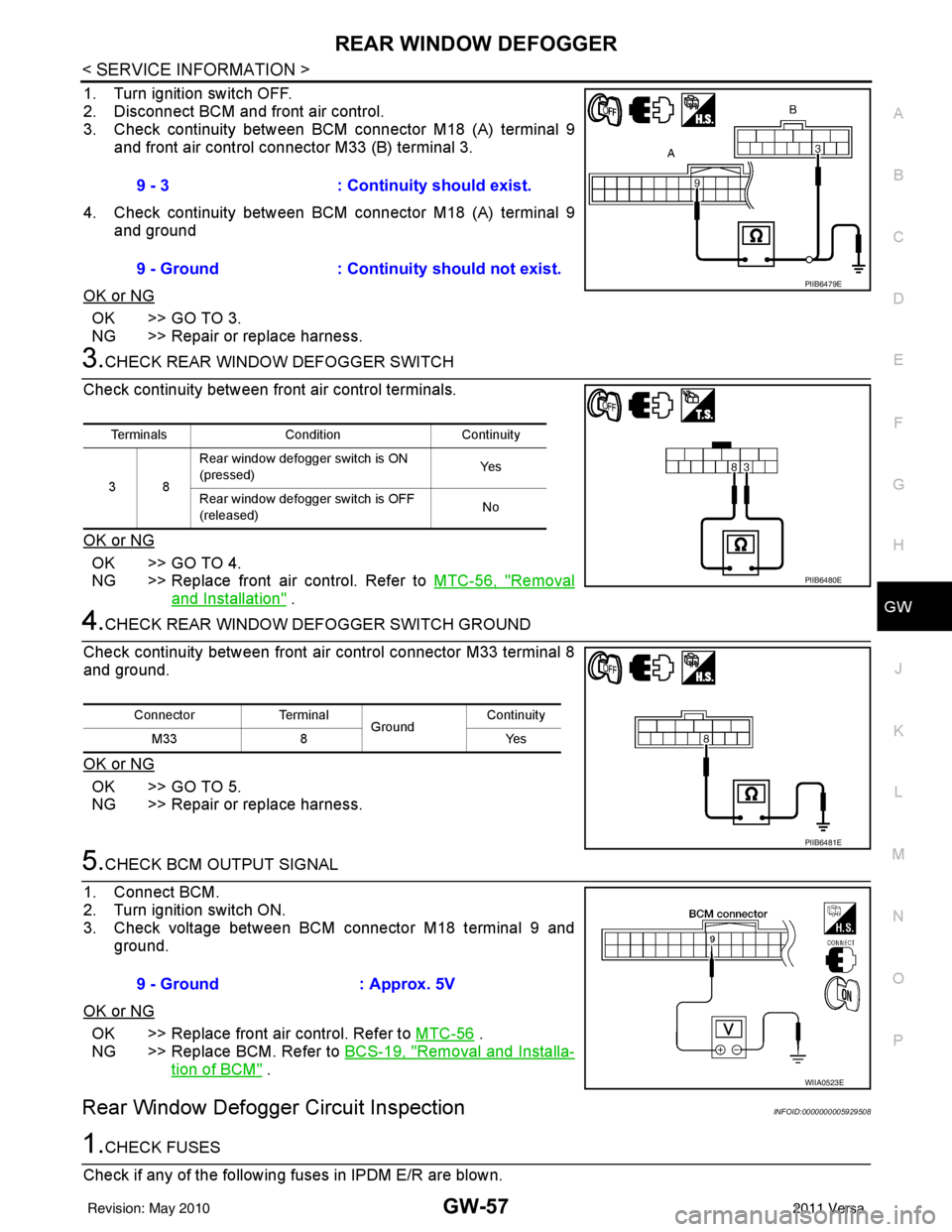
1. Turn ignition switch OFF.
2. Disconnect BCM and front air control.
3. Check continuity between BCM connector M18 (A) terminal 9 and front air control connector M33 (B) terminal 3.
4. Check continuity between BCM connector M18 (A) terminal 9 and ground
OK or NG
OK >> GO TO 3.
NG >> Repair or replace harness.
3.CHECK REAR WINDOW DEFOGGER SWITCH
Check continuity between fr ont air control terminals.
OK or NG
OK >> GO TO 4.
NG >> Replace front air control. Refer to MTC-56, "
Removal
and Installation" .
4.CHECK REAR WINDOW DEFOGGER SWITCH GROUND
Check continuity between front air control connector M33 terminal 8
and ground.
OK or NG
OK >> GO TO 5.
NG >> Repair or replace harness.
5.CHECK BCM OUTPUT SIGNAL
1. Connect BCM.
2. Turn ignition switch ON.
3. Check voltage between BCM connector M18 terminal 9 and ground.
OK or NG
OK >> Replace front air control. Refer to MTC-56 .
NG >> Replace BCM. Refer to BCS-19, "
Removal and Installa-
tion of BCM" .
Rear Window Defogger Circuit InspectionINFOID:0000000005929508
1.CHECK FUSES
Check if any of the following fuses in IPDM E/R are blown. 9 - 3
: Continuity should exist.
9 - Ground : Continuity should not exist.
PIIB6479E
Terminals Condition Continuity
38 Rear window defogger switch is ON
(pressed)
Ye s
Rear window defogger switch is OFF
(released) No
PIIB6480E
Connector
Terminal
Ground Continuity
8Y es
M33
PIIB6481E
9 - Ground : Approx. 5V
WIIA0523E
Revision: May 2010 2011 Versa
Page 2819 of 3787
DOOR MIRRORGW-65
< SERVICE INFORMATION >
C
DE
F
G H
J
K L
M A
B
GW
N
O P
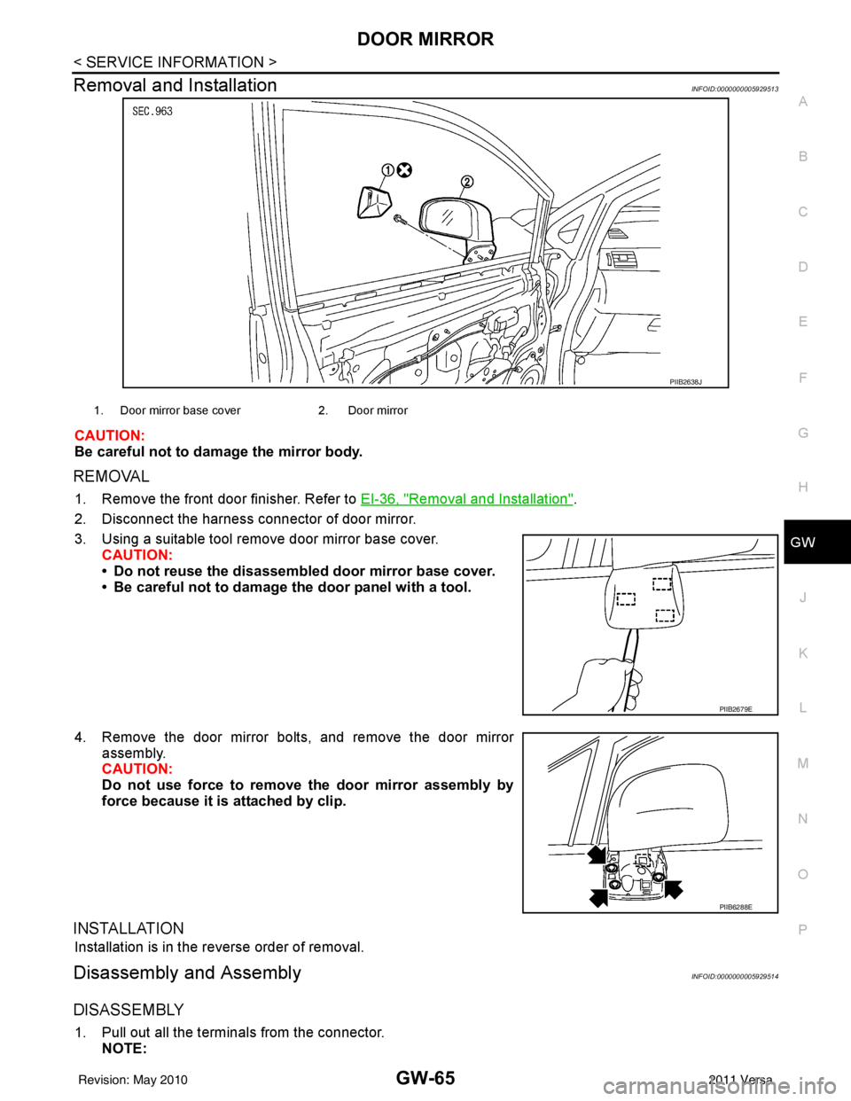
Removal and InstallationINFOID:0000000005929513
CAUTION:
Be careful not to damage the mirror body.
REMOVAL
1. Remove the front door finisher. Refer to EI-36, "Removal and Installation".
2. Disconnect the harness connector of door mirror.
3. Using a suitable tool remove door mirror base cover. CAUTION:
• Do not reuse the disassembl ed door mirror base cover.
• Be careful not to damage the door panel with a tool.
4. Remove the door mirror bolts, and remove the door mirror assembly.
CAUTION:
Do not use force to remove the door mirror assembly by
force because it is attached by clip.
INSTALLATION
Installation is in the reverse order of removal.
Disassembly and AssemblyINFOID:0000000005929514
DISASSEMBLY
1. Pull out all the terminals from the connector.
NOTE:
PIIB2638J
1. Door mirror base cover 2. Door mirror
PIIB2679E
PIIB6288E
Revision: May 2010 2011 Versa
Page 2823 of 3787

IP-2
< PRECAUTION >
PRECAUTIONS
PRECAUTION
PRECAUTIONS
Precaution for Supplemental Restraint System (SRS) "AIR BAG" and "SEAT BELT
PRE-TENSIONER"
INFOID:0000000005929584
The Supplemental Restraint System such as “A IR BAG” and “SEAT BELT PRE-TENSIONER”, used along
with a front seat belt, helps to reduce the risk or severity of injury to the driver and front passenger for certain
types of collision. This system includes seat belt switch inputs and dual stage front air bag modules. The SRS
system uses the seat belt switches to determine the front air bag deployment, and may only deploy one front
air bag, depending on the severity of a collision and w hether the front occupants are belted or unbelted.
Information necessary to service the system safely is included in the SRS and SB section of this Service Man-
ual.
WARNING:
• To avoid rendering the SRS inopera tive, which could increase the risk of personal injury or death in
the event of a collision which would result in air bag inflation, all maintenance must be performed by
an authorized NISSAN/INFINITI dealer.
• Improper maintenance, including in correct removal and installation of the SRS, can lead to personal
injury caused by unintent ional activation of the system. For re moval of Spiral Cable and Air Bag
Module, see the SRS section.
• Do not use electrical test equipmen t on any circuit related to the SRS unless instructed to in this
Service Manual. SRS wiring harn esses can be identified by yellow and/or orange harnesses or har-
ness connectors.
PRECAUTIONS WHEN USING POWER TOOLS (AIR OR ELECTRIC) AND HAMMERS
WARNING:
• When working near the Airbag Diagnosis Sensor Unit or other Airbag System sensors with the Igni-
tion ON or engine running, DO NOT use air or electri c power tools or strike near the sensor(s) with a
hammer. Heavy vibration could activate the sensor( s) and deploy the air bag(s), possibly causing
serious injury.
• When using air or electric power tools or hammers , always switch the Ignition OFF, disconnect the
battery, and wait at least 3 minu tes before performing any service.
Precaution Necessary for Steering W heel Rotation After Battery Disconnect
INFOID:0000000005929585
NOTE:
• This Procedure is applied only to models with Intelligent Key system and NATS (NISSAN ANTI-THEFT SYS-
TEM).
• Remove and install all control units after disconnecting both battery cables with the ignition knob in the
″LOCK ″ position.
• Always use CONSULT-III to perform self-diagnosis as a part of each function inspection after finishing work.
If DTC is detected, perform trouble diagnosis according to self-diagnostic results.
For models equipped with the Intelligent Key system and NATS, an electrically controlled steering lock mech-
anism is adopted on the key cylinder.
For this reason, if the battery is disconnected or if the battery is discharged, the steering wheel will lock and
steering wheel rotation will become impossible.
If steering wheel rotation is required when battery pow er is interrupted, follow the procedure below before
starting the repair operation.
OPERATION PROCEDURE
1. Connect both battery cables. NOTE:
Supply power using jumper cables if battery is discharged.
2. Use the Intelligent Key or mechanical key to turn the ignition switch to the ″ACC ″ position. At this time, the
steering lock will be released.
3. Disconnect both battery cables. The steering lock will remain released and the steering wheel can be rotated.
4. Perform the necessary repair operation.
Revision: May 2010 2011 Versa