Page 1808 of 3787
EC-514
< SERVICE INFORMATION >[MR18DE]
PRECAUTIONS
•
When installing C.B. ham radio or a mobile phone, be sure to
observe the following as it m ay adversely affect electronic
control systems depending on installation location.
- Keep the antenna as far as possi ble from the electronic con-
trol units.
- Keep the antenna feeder line more than 20 cm (8 in) away
from the harness of electronic controls.
Do not let them run parallel for a long distance.
- Adjust the antenna and feeder line so that the standing-wave
radio can be kept smaller.
- Be sure to ground the radio to vehicle body.
SEF708Y
Revision: May 2010 2011 Versa
Page 3473 of 3787
HARNESSPG-53
< SERVICE INFORMATION >
C
DE
F
G H
I
J
L
M A
B
PG
N
O P
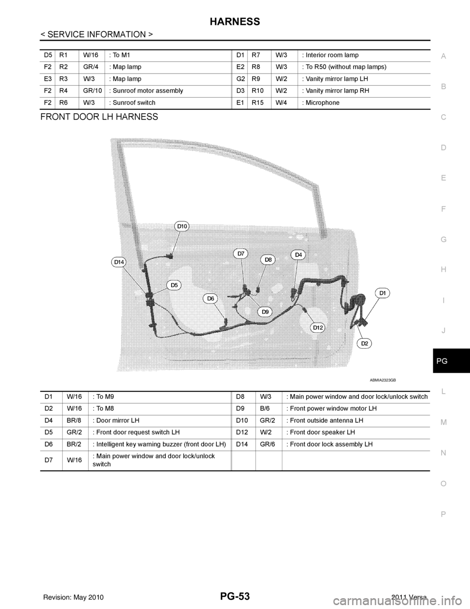
FRONT DOOR LH HARNESS
D5 R1 W/16 : To M1 D1 R7 W/3 : Interior room lamp
F2 R2 GR/4 : Map lamp E2 R8 W/3 : To R50 (without map lamps)
E3 R3 W/3 : Map lamp G2 R9 W/2 : Vanity mirror lamp LH
F2 R4 GR/10 : Sunroof motor assembly D3 R10 W/2 : Vanity mirror lamp RH
F2 R6 W/3 : Sunroof switch E1 R15 W/4 : Microphone
ABMIA2323GB
D1 W/16 : To M9D8 W/3 : Main power window and door lock/unlock switch
D2 W/16 : To M8 D9 B/6 : Front power window motor LH
D4 BR/8 : Door mirror LH D10 GR/2 : Front outside antenna LH
D5 GR/2 : Front door request switch LH D12 W/2 : Front door speaker LH
D6 BR/2 : Intelligent key warning buzzer (front door LH) D14 GR/6 : Front door lock assembly LH
D7 W/16 : Main power window and door lock/unlock
switch
Revision: May 2010
2011 Versa
Page 3479 of 3787

HARNESSPG-59
< SERVICE INFORMATION >
C
DE
F
G H
I
J
L
M A
B
PG
N
O P
H/LAMP LT Headlamp
H/PHON AV Hands Free Telephone
HORN WW Horn
HO2S2 EC Heated Oxygen Sensor 2
HO2S2H EC Heated Oxygen Sensor 2 Heater
IATS EC Intake Air Temperature Sensor
IGNSYS EC Ignition System
I/KEY BL Intelligent Key System
ILL LT Illumination
INJECT EC Injector
INT/L LT Room/Map, Vanity and Luggage Lamps
IVC EC Intake Valve Timing Control Solenoid Valve
KEYLES BL Remote Keyless Entry System
KS EC Knock Sensor
LPSV AT Line Pressure Solenoid Valve
LPSV CVT Line Pressure Solenoid Valve
L/USSV CVT Lock-up Select Solenoid Valve
MAFS EC Mass Air Flow Sensor
MAIN AT Main Power Supply and Ground Circuit
MAIN EC Main Power Supply and Ground Circuit
METER DI Speedometer, Tachometer, Temp. and Fuel Gauges
MIL/DL EC Malfunction Indicator Lamp
MIRROR GW Door Mirror
NATS BL Nissan Anti-Theft System
NONDTC AT Non-detectable Item
NONDTC CVT Non-detectable Item
ODSW CVT Overdrive Control Switch
OVRCSV AT Over Run Clutch Solenoid Valve
P/SCKT WW Power Socket
PGC/V EC EVAP Canister Purge Vo lume Control Solenoid Valve
PHASE EC Camshaft Position Sensor (PHASE)
PNP/SW EC Park/Neutral Position Switch
POS EC Crankshaft Position Sensor (POS)
POWER CVT Transmission Control Module (Power Supply)
PRE/SE EC EVAP Control System Pressure Sensor
PRIPS CVT Primary Pressure Sensor
PRSCVT CVT Primary Speed Sensor CVT (Input Speed Sensor)
PT/SEN AT Powertrain Revolution Sensor
RP/SEN EC Refrigerant Pressure Sensor
SECPS CVT Secondary Pressure Sensor
SECPSV CVT Secondary Speed Sensor CVT (Input Speed Sensor)
SEN/PW EC Sensor Power Supply
SESCVT CVT Secondary Pressure Sensor Solenoid Valve
SHIFT AT A/T Shift Lock System
SHIFT CVT CVT Shift Lock System
SROOF RF Sunroof
SRS SRS Supplemental Restraint System
SSV/A AT Shift Solenoid Valve A
SSV/B AT Shift Solenoid Valve B
START SC Starting System
STM CVT Step Motor
STOP/L LT Stop Lamp
Revision: May 2010 2011 Versa
Page 3586 of 3787
SC-8
< SERVICE INFORMATION >
BATTERY
INSTALLATION (All except MR18DE with CVT)
Installation is in the reverse order of removal.
CAUTION:
When connecting, connect the battery positive terminal first.
Reset electronic systems as necessary. Refer to SC-8, "
Required Procedure After Battery Disconnection".
REMOVAL (MR18DE with CVT)
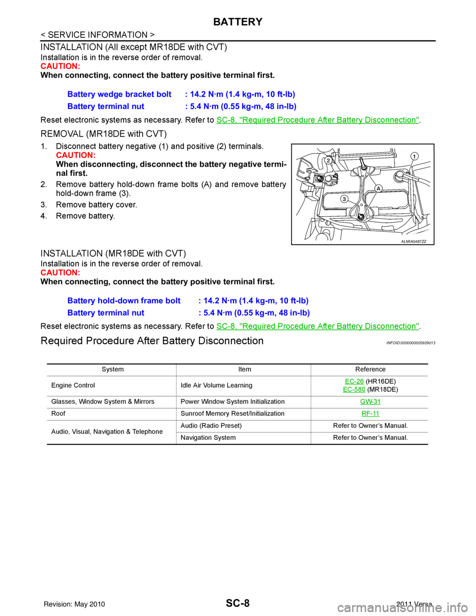
1. Disconnect battery negative (1) and positive (2) terminals.
CAUTION:
When disconnecting, disconnect the battery negative termi-
nal first.
2. Remove battery hold-down frame bolts (A) and remove battery hold-down frame (3).
3. Remove battery cover.
4. Remove battery.
INSTALLATION (MR18DE with CVT)
Installation is in the reverse order of removal.
CAUTION:
When connecting, connect the battery positive terminal first.
Reset electronic systems as necessary. Refer to SC-8, "
Required Procedure After Battery Disconnection".
Required Procedure After Battery DisconnectionINFOID:0000000005929013
Battery wedge bracket bolt : 14.2 N·m (1.4 kg-m, 10 ft-lb)
Battery terminal nut : 5.4 N·m (0.55 kg-m, 48 in-lb)
ALMIA0487ZZ
Battery hold-down frame bolt : 14.2 N·m (1.4 kg-m, 10 ft-lb)
Battery terminal nut : 5.4 N·m (0.55 kg-m, 48 in-lb)
System ItemReference
Engine Control Idle Air Volume Learning EC-26
(HR16DE)
EC-580
(MR18DE)
Glasses, Window System & Mirrors Power Window System Initialization GW-31
RoofSunroof Memory Reset/Initialization RF-11
Audio, Visual, Navigation & TelephoneAudio (Radio Preset)
Refer to Owner’s Manual.
Navigation System Refer to Owner’s Manual.
Revision: May 2010 2011 Versa
![NISSAN TIIDA 2011 Service Repair Manual EC-514
< SERVICE INFORMATION >[MR18DE]
PRECAUTIONS
•
When installing C.B. ham radio or a mobile phone, be sure to
observe the following as it m ay adversely affect electronic
control systems dependi](/manual-img/5/57396/w960_57396-1807.png "NISSAN TIIDA 2011 Service Repair Manual EC-514
< SERVICE INFORMATION >[MR18DE]
PRECAUTIONS
•
When installing C.B. ham radio or a mobile phone, be sure to
observe the following as it m ay adversely affect electronic
control systems dependi")