2011 NISSAN TIIDA oil type
[x] Cancel search: oil typePage 3333 of 3787
OIL
MTC-17
< SERVICE INFORMATION >
C
D E
F
G H
I
K L
M A
B
MTC
N
O P
OIL
Maintenance of Oil Qu antity in CompressorINFOID:0000000005930838
The oil in the compressor circulates through the system with the refrigerant. Add oil to compressor when
replacing any component or after a large refrigerant leakage occurred. It is important to maintain the specified
amount.
If oil quantity is not maintained properly , the following malfunctions may result:
• Lack of oil: May lead to a seized compressor.
• Excessive oil: Inadequate cooling (thermal exchange interference)
OIL
OIL ADJUSTING PROCEDURE FOR COMPONENTS REPLACEMENT EXCEPT COMPRESSOR
After replacing any of the following major components, add the correct amount of oil to the system.
Amount Of Oil To Be Added
*1: If refrigerant leak is small, no addition of oil is needed.
OIL ADJUSTING PROCEDURE FOR COMPRESSOR REPLACEMENT
TYPE 1 Compressor (CR-10) : NISSAN A/C System Oil Type R
TYPE 2 Compressor (CSV511) : NISSAN A/C System Oil Type S
Part replaced Oil to be added to system
Remarks
Amount of oil
m (US fl oz, Imp fl oz)
Evaporator 35 (1.2, 1.2)-
Condenser 15 (0.5, 0.5)-
Liquid tank 5 (0.2, 0.2)-
In case of refrigerant leak 30 (1.0, 1.1)
Large leak
None *1 Small leak
*1
Revision: May 2010 2011 Versa
Page 3374 of 3787
MTC-58
< SERVICE INFORMATION >
THERMO CONTROL AMPLIFIER
THERMO CONTROL AMPLIFIER
Removal and InstallationINFOID:0000000005930859
NOTE:
Only MR18DE - TYPE 2 systems are equipped with a thermo control amplifier.
REMOVAL
1. Remove evaporator. Refer to MTC-91, "Removal and Installation of Evaporator" .
CAUTION:
Cap or wrap the joint of the pipe with suitable ma terial such as vinyl tape to avoid the entry of air.
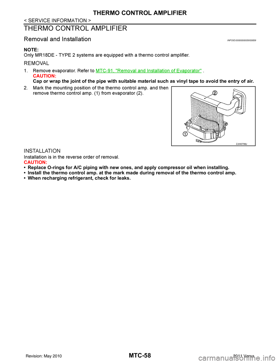
2. Mark the mounting position of the thermo control amp. and then
remove thermo control amp. (1) from evaporator (2).
INSTALLATION
Installation is in the reverse order of removal.
CAUTION:
• Replace O-rings for A/C piping with new ones, and apply compressor oil when installing.
• Install the thermo control amp. at the mark made during removal of the thermo control amp.
• When recharging refrigerant, check for leaks.
ZJIA0798J
Revision: May 2010 2011 Versa
Page 3376 of 3787
MTC-60
< SERVICE INFORMATION >
A/C UNIT ASSEMBLY
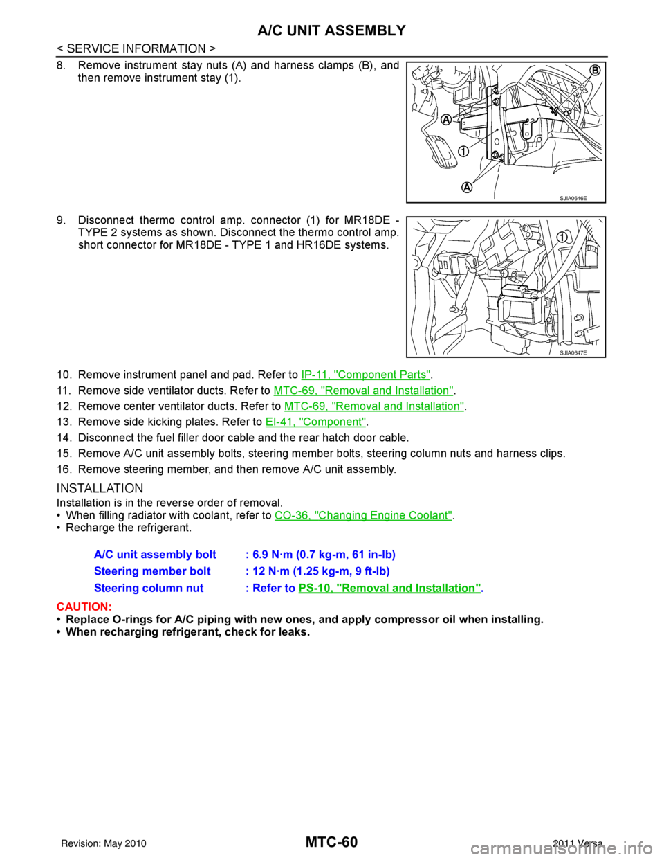
8. Remove instrument stay nuts (A) and harness clamps (B), andthen remove instrument stay (1).
9. Disconnect thermo control amp. connector (1) for MR18DE - TYPE 2 systems as shown. Di sconnect the thermo control amp.
short connector for MR18DE - TYPE 1 and HR16DE systems.
10. Remove instrument panel and pad. Refer to IP-11, "
Component Parts".
11. Remove side ventilator ducts. Refer to MTC-69, "
Removal and Installation".
12. Remove center ventilator ducts. Refer to MTC-69, "
Removal and Installation".
13. Remove side kicking plates. Refer to EI-41, "
Component".
14. Disconnect the fuel filler door cable and the rear hatch door cable.
15. Remove A/C unit assembly bolts, steering member bolts, steering column nuts and harness clips.
16. Remove steering member, and then remove A/C unit assembly.
INSTALLATION
Installation is in the reverse order of removal.
• When filling radiator with coolant, refer to CO-36, "
Changing Engine Coolant".
• Recharge the refrigerant.
CAUTION:
• Replace O-rings for A/C piping with new ones, and apply compressor oil when installing.
• When recharging refrigerant, check for leaks.
SJIA0646E
SJIA0647E
A/C unit assembly bolt : 6.9 N·m (0.7 kg-m, 61 in-lb)
Steering member bolt : 12 N·m (1.25 kg-m, 9 ft-lb)
Steering column nut : Refer to PS-10, "
Removal and Installation".
Revision: May 2010 2011 Versa
Page 3397 of 3787
REFRIGERANT LINESMTC-81
< SERVICE INFORMATION >
C
DE
F
G H
I
K L
M A
B
MTC
N
O P
INSPECTION FOR CLUTCH DISC TO PULLEY CLEARANCE
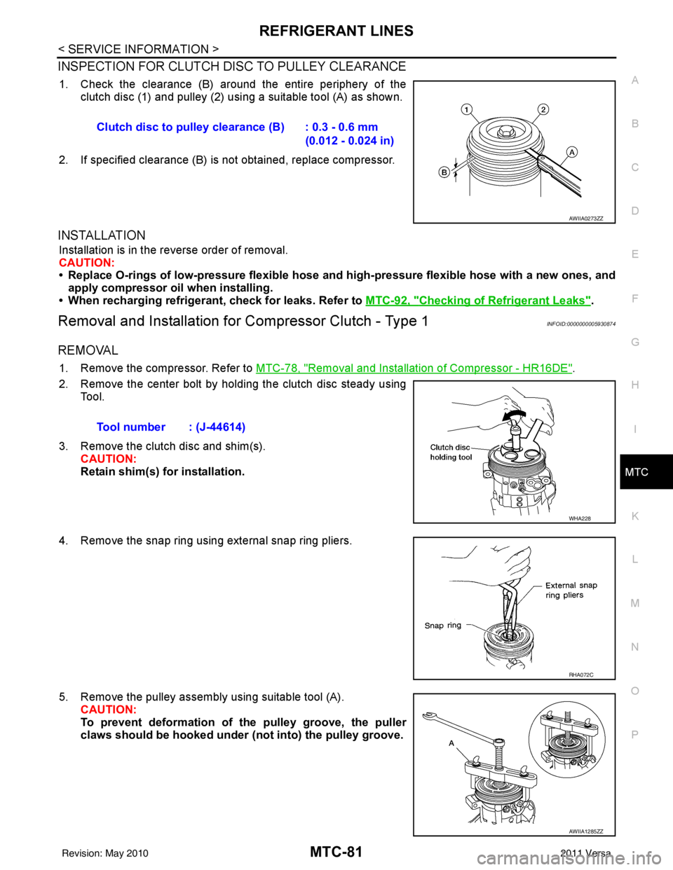
1. Check the clearance (B) around the entire periphery of the clutch disc (1) and pulley (2) usi ng a suitable tool (A) as shown.
2. If specified clearance (B) is not obtained, replace compressor.
INSTALLATION
Installation is in the reverse order of removal.
CAUTION:
• Replace O-rings of low-pressure flexible hose and high-pressure flexible hose with a new ones, and
apply compressor oil when installing.
• When recharging refrigerant, check for leaks. Refer to MTC-92, "
Checking of Refrigerant Leaks".
Removal and Installation for Compressor Clutch - Type 1INFOID:0000000005930874
REMOVAL
1. Remove the compressor. Refer to MTC-78, "Removal and Installation of Compressor - HR16DE".
2. Remove the center bolt by holding the clutch disc steady using Tool.
3. Remove the clutch disc and shim(s). CAUTION:
Retain shim(s) for installation.
4. Remove the snap ring using external snap ring pliers.
5. Remove the pulley assembly using suitable tool (A). CAUTION:
To prevent deformation of the pulley groove, the puller
claws should be hooked under (not into) the pulley groove.
Clutch disc to pulley clearance (B) : 0.3 - 0.6 mm
(0.012 - 0.024 in)
AWIIA0273ZZ
Tool number : (J-44614)
WHA228
RHA072C
AWIIA1285ZZ
Revision: May 2010 2011 Versa
Page 3407 of 3787
REFRIGERANT LINESMTC-91
< SERVICE INFORMATION >
C
DE
F
G H
I
K L
M A
B
MTC
N
O P
Installation is in the reverse order of removal.
CAUTION:
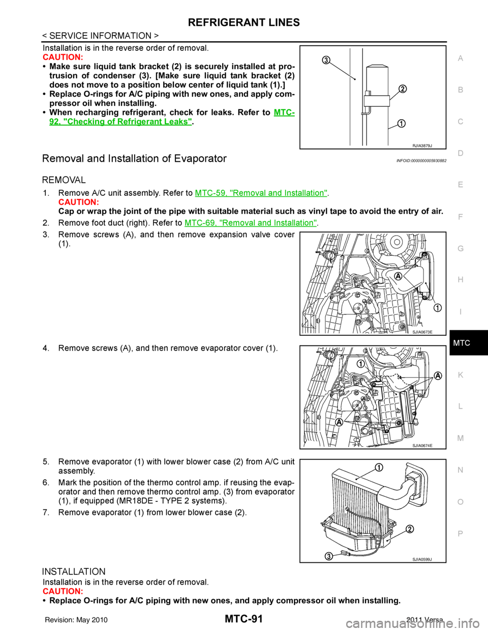
• Make sure liquid tank bracket (2) is securely installed at pro- trusion of condenser (3). [Make sure liquid tank bracket (2)
does not move to a position belo w center of liquid tank (1).]
• Replace O-rings for A/C piping with new ones, and apply com-
pressor oil when installing.
• When recharging refrigerant, check for leaks. Refer to MTC-
92, "Checking of Refrigerant Leaks".
Removal and Installation of EvaporatorINFOID:0000000005930882
REMOVAL
1. Remove A/C unit assembly. Refer to MTC-59, "Removal and Installation".
CAUTION:
Cap or wrap the joint of the pipe with suitable ma terial such as vinyl tape to avoid the entry of air.
2. Remove foot duct (right). Refer to MTC-69, "
Removal and Installation".
3. Remove screws (A), and then remove expansion valve cover (1).
4. Remove screws (A), and then remove evaporator cover (1).
5. Remove evaporator (1) with lower blower case (2) from A/C unit assembly.
6. Mark the position of the thermo control amp. if reusing the evap-
orator and then remove thermo control amp. (3) from evaporator
(1), if equipped (MR18D E - TYPE 2 systems).
7. Remove evaporator (1) from lower blower case (2).
INSTALLATION
Installation is in the reverse order of removal.
CAUTION:
• Replace O-rings for A/C piping with new on es, and apply compressor oil when installing.
RJIA3879J
SJIA0673E
SJIA0674E
SJIA0599J
Revision: May 2010 2011 Versa
Page 3408 of 3787
MTC-92
< SERVICE INFORMATION >
REFRIGERANT LINES
• If reusing the evaporator, install the thermo control amp. at the position marked when removing the
thermo control amp., if equipped (MR18DE - TYPE 2 systems).
• When recharging refrigerant, check for leaks.
Removal and Installation of Expansion ValveINFOID:0000000005930883
REMOVAL
1. Use the recovery/recycling equipment to evacuate the refrigerant.
2. Remove cowl top cover. Refer to EI-24, "
Removal and Installation".
3. Remove lower dash insulator.
4. Disconnect low-pressure flexible hose and high-pressure pipe from evaporator. Refer to MTC-59,
"Removal and Installation".
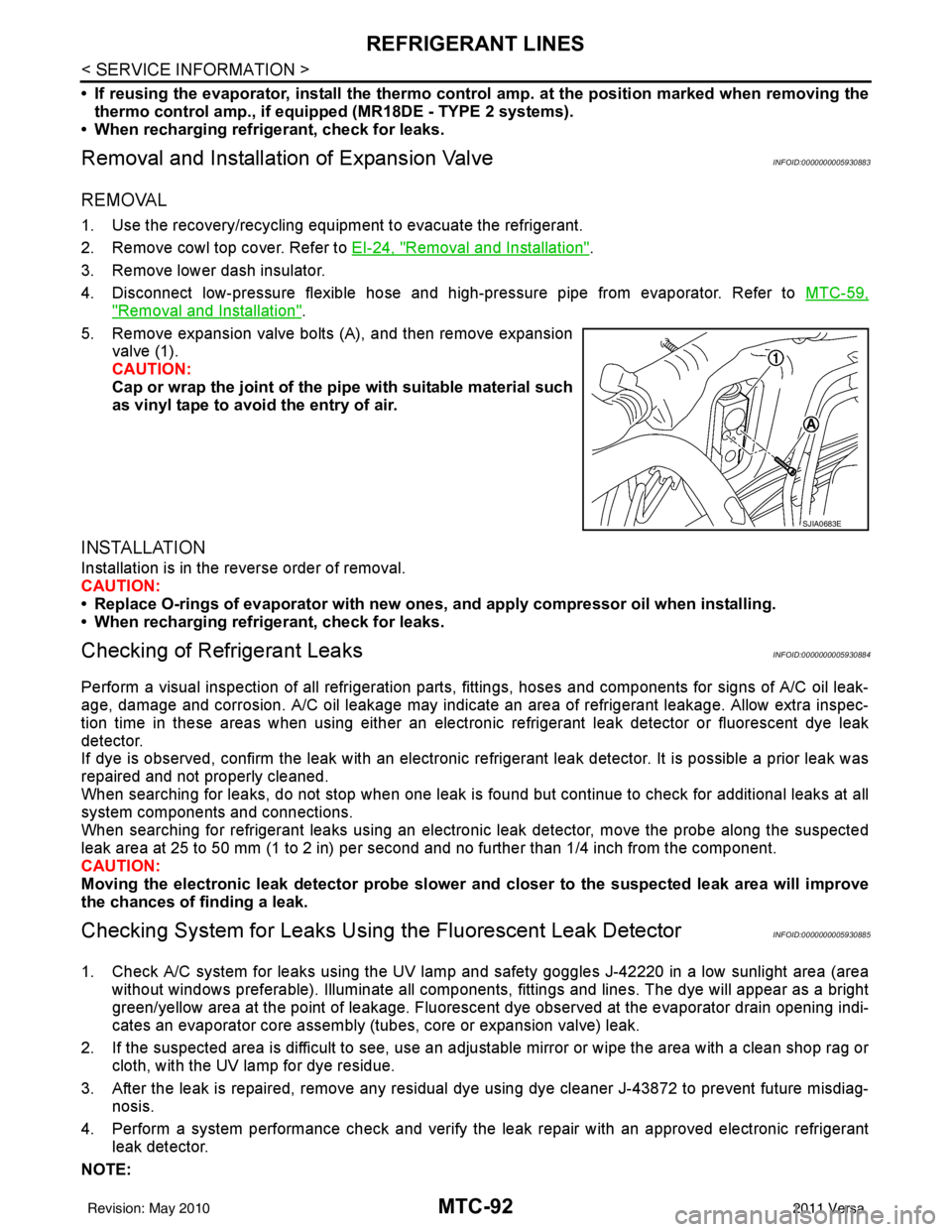
5. Remove expansion valve bolts (A), and then remove expansion valve (1).
CAUTION:
Cap or wrap the joint of the pi pe with suitable material such
as vinyl tape to avoid the entry of air.
INSTALLATION
Installation is in the reverse order of removal.
CAUTION:
• Replace O-rings of evaporator with new ones, and apply compressor oil when installing.
• When recharging refrigerant, check for leaks.
Checking of Refrigerant LeaksINFOID:0000000005930884
Perform a visual inspection of all refrigeration parts, fittings, hoses and components for signs of A/C oil leak-
age, damage and corrosion. A/C oil leakage may indicate an area of refrigerant leakage. Allow extra inspec-
tion time in these areas when using either an electronic refrigerant leak detector or fluorescent dye leak
detector.
If dye is observed, confirm the leak with an electronic refrigerant leak detector. It is possible a prior leak was
repaired and not properly cleaned.
When searching for leaks, do not stop when one leak is found but continue to check for additional leaks at all
system components and connections.
When searching for refrigerant leaks using an electronic leak detector, move the probe along the suspected
leak area at 25 to 50 mm (1 to 2 in) per second and no further than 1/4 inch from the component.
CAUTION:
Moving the electronic leak detector probe slower an d closer to the suspected leak area will improve
the chances of finding a leak.
Checking System for Leaks Using the Fluorescent Leak DetectorINFOID:0000000005930885
1. Check A/C system for leaks using the UV lamp and safety goggles J-42220 in a low sunlight area (area
without windows preferable). Illuminate all components, fittings and lines. The dye will appear as a bright
green/yellow area at the point of leakage. Fluoresce nt dye observed at the evaporator drain opening indi-
cates an evaporator core assembly (tubes, core or expansion valve) leak.
2. If the suspected area is difficult to see, use an adjustable mirror or wipe the area with a clean shop rag or cloth, with the UV lamp for dye residue.
3. After the leak is repaired, remove any residual dye using dye cleaner J-43872 to prevent future misdiag- nosis.
4. Perform a system performance chec k and verify the leak repair with an approved electronic refrigerant
leak detector.
NOTE:
SJIA0683E
Revision: May 2010 2011 Versa
Page 3412 of 3787
MTC-96
< SERVICE INFORMATION >
SERVICE DATA AND SPECIFICATIONS (SDS)
SERVICE DATA AND SPECIFICATIONS (SDS)
CompressorINFOID:0000000005930888
OilINFOID:0000000005930889
RefrigerantINFOID:0000000005930890
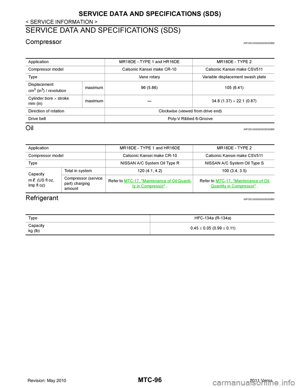
ApplicationMR18DE - TYPE 1 and HR16DE MR18DE - TYPE 2
Compressor model Calsonic Kansei make CR-10Calsonic Kansei make CSV511
Type Vane rotaryVariable displacement swash plate
Displacement
cm
3 (in3) / revolution maximum
96 (5.86) 105 (6.41)
Cylinder bore × stroke
mm (in) maximum
— 34.8 (1.37) × 22.1 (0.87)
Direction of rotation Clockwise (viewed from drive end)
Drive belt Poly-V Ribbed 6-Groove
ApplicationMR18DE - TYPE 1 and HR16DE MR18DE - TYPE 2
Compressor model Calsonic Kansei make CR-10Calsonic Kansei make CSV511
Type NISSAN A/C System Oil Type RNISSAN A/C System Oil Type S
Capacity
m (US fl oz,
lmp fl oz) Total in system
120 (4.1, 4.2) 100 (3.4, 3.5)
Compressor (service
part) charging
amount Refer to
MTC-17, "
Maintenance of Oil Quanti-
ty in Compressor" . Refer to MTC-17, "
Maintenance of Oil
Quantity in Compressor" .
Ty p e
HFC-134a (R-134a)
Capacity
kg (lb) 0.45
± 0.05 (0.99 ± 0.11)
Revision: May 2010 2011 Versa
Page 3559 of 3787
RSU-6
< SERVICE INFORMATION >
REAR SUSPENSION ASSEMBLY
REAR SUSPENSION ASSEMBLY
On-Vehicle Inspection and ServiceINFOID:0000000005931084
Make sure the mounting conditions (looseness, backlash) of each component and component conditions
(wear, damage) are within specifications.
SHOCK ABSORBER INSPECTION
Check shock absorber for oil leakage, damage and replace it if necessary.
Wheel AlignmentInspectionINFOID:0000000005931085
DESCRIPTION
Measure wheel alignment under unladen conditions.
NOTE:
“Unladen conditions” means that fuel, engine coolant, and lubricant are full. Spare tire, jack, hand tools and
mats are in designated positions.
PRELIMINARY
Check the following:
1. Tires for improper air pressure and wear.
2. Road wheels for runout. Refer to WT-6
.
3. Wheel bearing axial end play. Refer to RAX-6, "
On-Vehicle Inspection and Service" .
4. Shock absorber operation.
5. Each mounting part of suspension for looseness and deformation.
6. Rear suspension beam for cracks, deformation, and other damage.
7. Vehicle height (posture).
GENERAL INFORMATION AND RECOMMENDATIONS
1. A Four-Wheel Thrust Alignment should be performed. • This type of alignment is recommended for any NISSAN vehicle.
• The four-wheel “thrust” process helps ensure that the vehicle is properly aligned and the steering wheel
is centered.
• The alignment machine itself should be ca pable of accepting any NISSAN vehicle.
• The alignment machine should be checked to ensure that it is level.
2. Make sure the alignment machine is properly calibrated. • Your alignment machine should be regularly calibrated in order to give correct information.
• Check with the manufacturer of your specific al ignment machine for their recommended Service/Cali-
bration Schedule.
THE ALIGNMENT PROCESS
IMPORTANT: Use only the alignment specifications listed in this Service Manual. Refer to RSU-13, "Wheel
Alignment (Unladen*)" .
1. When displaying the alignment settings, many alignment machines use “indicators”: (Green/red, plus or minus, Go/No Go). Do NOT use these indicators.
• The alignment specifications programmed into your alignment machine that operate these indicators may not be correct.
• This may result in an ERROR.
2. Some newer alignment machines are equipped with an optional “Rolling Compensation” method to “com- pensate” the sensors (alignment targets or head units). Do NOT use this “Rolling Compensation”
method.
• Use the “Jacking Compensation” method. After inst alling the alignment targets or head units, raise the
vehicle and rotate the wheels 1/2 turn both ways.
• See Instructions in the alignment machine you are using for more information.
CAMBER INSPECTION
Revision: May 2010 2011 Versa