Page 2345 of 3787
FRONT BUMPEREI-15
< ON-VEHICLE REPAIR >
C
DE
F
G H
J
K L
M A
B
EI
N
O P
ON-VEHICLE REPAIR
FRONT BUMPER
Removal and InstallationINFOID:0000000005929554
1. Bumper stay RH 2. Bumper reinforcement (production) 3. Bumper energy absorber
4. Engine undercover 5. Front valance 6. Front bumper fascia
7. Access cover 8. Fog lamp opening finisher (without
fog lamps) 9. Fog lamp opening finisher (with fog
lamps)
WIIA1405E
Revision: May 2010 2011 Versa
Page 2346 of 3787

EI-16
< ON-VEHICLE REPAIR >
FRONT BUMPER
CAUTION:
Bumper fascia is made of resin. Do not apply strong force to it, and be careful to prevent contact with
oil.
REMOVAL
1. Open hood.
2. Remove front grille. Refer to EI-23
.
3. Remove front fender protectors RH/LH. Refer to EI-26
.
4. Remove front valance and engine undercover.
5. Remove screws of front bumper fascia RH/LH.
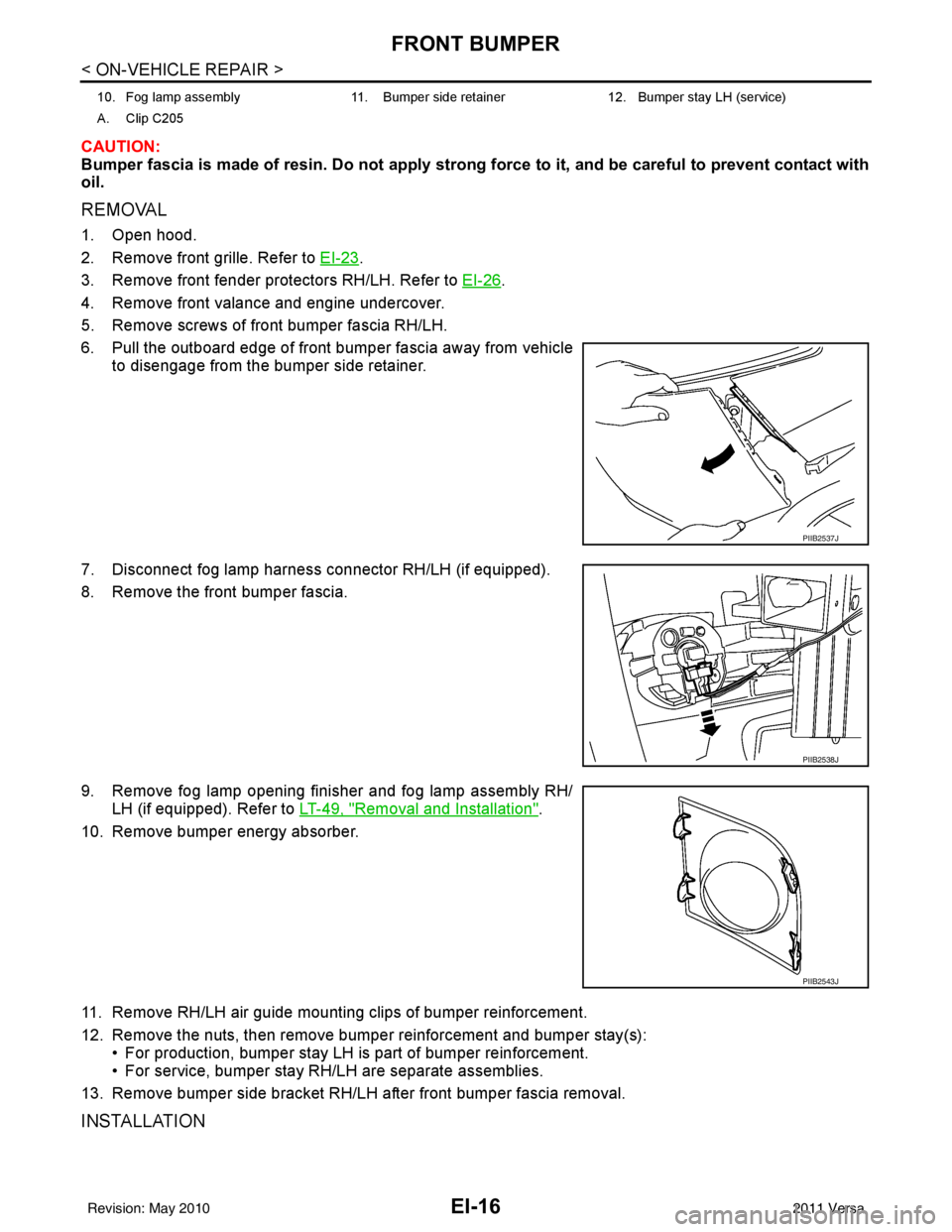
6. Pull the outboard edge of front bumper fascia away from vehicle to disengage from the bumper side retainer.
7. Disconnect fog lamp harness connector RH/LH (if equipped).
8. Remove the front bumper fascia.
9. Remove fog lamp opening finisher and fog lamp assembly RH/ LH (if equipped). Refer to LT-49, "
Removal and Installation".
10. Remove bumper energy absorber.
11. Remove RH/LH air guide mounting clips of bumper reinforcement.
12. Remove the nuts, then remove bumper reinforcement and bumper stay(s): • For production, bumper stay LH is part of bumper reinforcement.
• For service, bumper stay RH/LH are separate assemblies.
13. Remove bumper side bracket RH/LH after front bumper fascia removal.
INSTALLATION
10. Fog lamp assembly 11. Bumper side retainer 12. Bumper stay LH (service)
A. Clip C205
PIIB2537J
PIIB2538J
PIIB2543J
Revision: May 2010 2011 Versa
Page 2347 of 3787
FRONT BUMPEREI-17
< ON-VEHICLE REPAIR >
C
DE
F
G H
J
K L
M A
B
EI
N
O P
Installation is in the reverse order of removal.
mm (in)
ALKIA1929ZZ
Component PortionMinimum Target Value Maximum
Front bumper - Hood Clearance A-A 4.0 (0.157) 6.0 (0.236)8.5 (0.335)
Front bumper - Hood Surface A-A-1.9 (0.075) 0.65 (0.026)2.65 (0.104)
Front bumper - Front grille B-B1.0 (0.039) 2.0 (0.079)3.0 (0.118)
Front bumper - Head lamp C-C0.3 (0.012) 2.0 (0.079)3.7 (0.146)
Front bumper - Front fender Clearance D-D 0.0 (0.000)0.0 (0.000)1.0 (0.039)
Front bumper - Front fender Surface D-D -0.35 (0.014)0.65 (0.026)1.65 (0.065)
Revision: May 2010 2011 Versa
Page 2350 of 3787
EI-20
< ON-VEHICLE REPAIR >
REAR BUMPER
6. Pull the rear bumper fascia side outward and release thebumper side bracket.
7. Remove rear bumper fascia upper clips and screws.
8. Release rear bumper upper retainer (1), then pull rear bumper fascia outward away from rear of vehicle.
9. Disconnect license lamp connector.
10. Remove energy absorbing foam and rear bumper reinforcement.
11. Remove the bumper side bracket (1) RH/LH. • : Vehicle front
INSTALLATION
Installation is in the reverse order of removal.
mm (in)
LIIA2579E
LIIA2580E
LIIA2581E
ALKIA1930ZZ
Component PortionMinimum Target Value Maximum
Rear bumper - Back door clearance A-A 4.0 (0.157)6.0 (0.236)8.0 (0.315)
Rear bumper - Rear combination lamp
clearance B-B
1.0 (0.039) 2.0 (0.079)3.5 (0.138)
Revision: May 2010 2011 Versa
Page 2351 of 3787

REAR BUMPEREI-21
< ON-VEHICLE REPAIR >
C
DE
F
G H
J
K L
M A
B
EI
N
O P
Removal and Installation - SedanINFOID:0000000005929557
REMOVAL
1. Open trunk lid.
2. Remove rear combination lamp RH/LH. Refer to LT-88, "
Removal and Installation".
3. Remove rear bumper fascia spring nuts and screws RH/LH.
4. Remove rear fender protector. Refer to EI-26, "
Removal and Installation".
5. Pull the rear bumper fascia side outward and release the bumper side bracket.
6. Remove rear bumper fascia upper clips and screws.
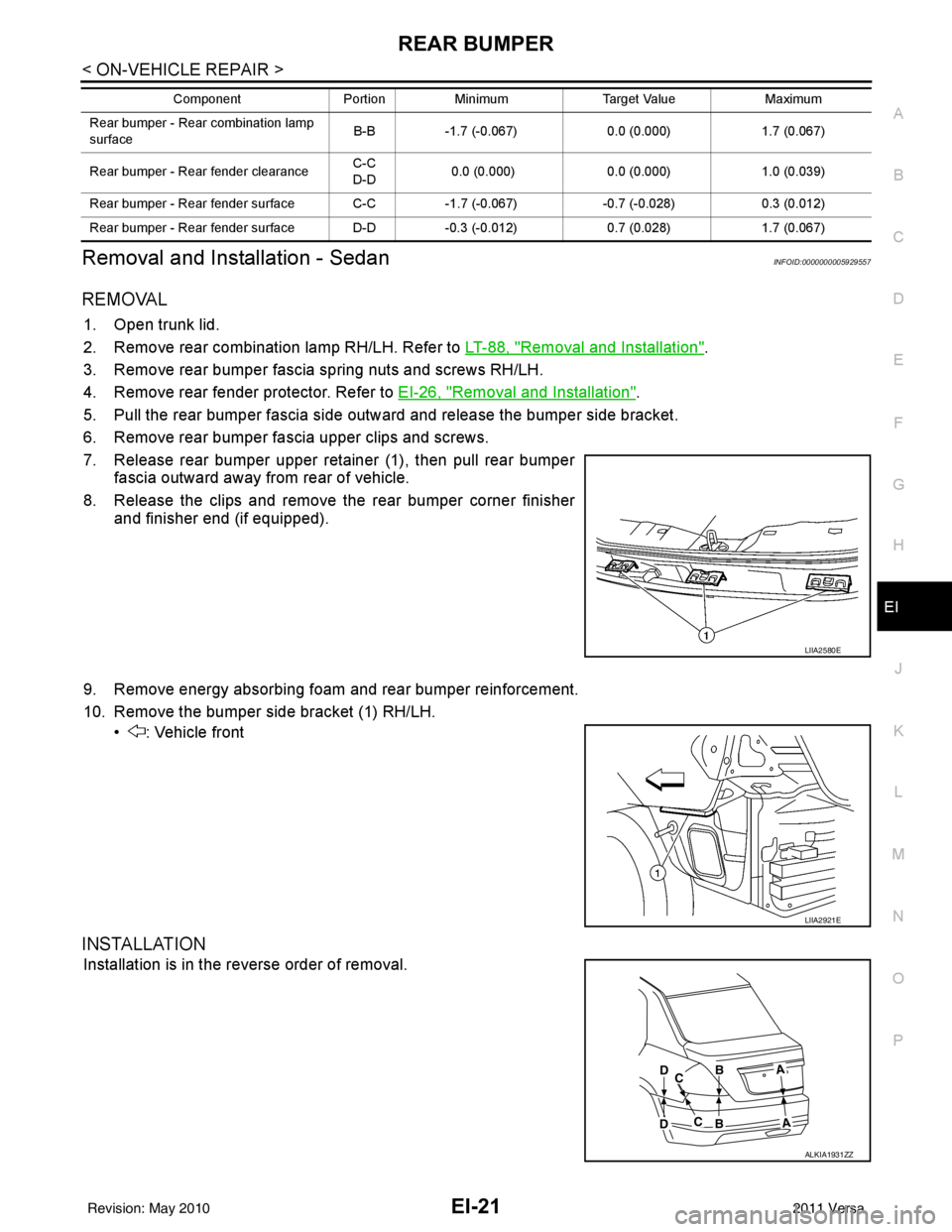
7. Release rear bumper upper retainer (1), then pull rear bumper fascia outward away from rear of vehicle.
8. Release the clips and remove the rear bumper corner finisher and finisher end (if equipped).
9. Remove energy absorbing foam and rear bumper reinforcement.
10. Remove the bumper side bracket (1) RH/LH. • : Vehicle front
INSTALLATION
Installation is in the reverse order of removal.
Rear bumper - Rear combination lamp
surface B-B
-1.7 (-0.067) 0.0 (0.000)1.7 (0.067)
Rear bumper - Rear fender clearance C-C
D-D
0.0 (0.000)
0.0 (0.000)1.0 (0.039)
Rear bumper - Rear fender surface C-C -1.7 (-0.067)-0.7 (-0.028) 0.3 (0.012)
Rear bumper - Rear fender surface D-D -0.3 (-0.012)0.7 (0.028)1.7 (0.067)
Component
PortionMinimum Target Value Maximum
LIIA2580E
LIIA2921E
ALKIA1931ZZ
Revision: May 2010 2011 Versa
Page 2353 of 3787
FRONT GRILLEEI-23
< ON-VEHICLE REPAIR >
C
DE
F
G H
J
K L
M A
B
EI
N
O P
FRONT GRILLE
Removal and InstallationINFOID:0000000005929558
REMOVAL
1. Open hood assembly.
2. Remove the clips, then remove upper radiator cover.
3. Remove the upper clips and release the lower pawls, then pull outward to remove the front grille.
INSTALLATION
Installation is in the reverse order of removal.
LIIA2564E
1. Upper radiator cover2. Front grille3. Front bumper fascia
4. Clip C205 Pawl
Revision: May 2010 2011 Versa
Page 2354 of 3787
EI-24
< ON-VEHICLE REPAIR >
COWL TOP
COWL TOP
Removal and InstallationINFOID:0000000005929559
REMOVAL
1. Remove front wiper arm RH/LH from vehicle. Refer to WW-20, "Removal and Installation of Front Wiper
Arms".
2. Disconnect washer tube.
3. Remove fender seal and fender cover RH/LH.
4. Release the cowl top seal clips, then remove cowl top seal.
LIIA2565E
1. Fender cover 2. Fender seal3. Washer tube
4. Cowl top seal 5. Cowl extension panel6. Dual lock fastener
7. Double-faced adhesive tape 8. Cowl top cover 9. Clip C205
10. EPT sealer 11. Cowl extension clip12. Cover
Clip CE103 Vehicle front
PIIB2555J
Revision: May 2010 2011 Versa
Page 2355 of 3787
COWL TOPEI-25
< ON-VEHICLE REPAIR >
C
DE
F
G H
J
K L
M A
B
EI
N
O P
5. Release the cowl extension clip (1) by prying the center pawls apart and pulling clip outward. Remove remaining clips, then
remove cowl top cover (2).
6. Disconnect and remove the front wiper motor and linkage assembly. Refer to WW-22, "
Removal and Installation of Front
Wiper Drive Assembly".
CAUTION:
To avoid damage, make sure to cover the lower edge of
windshield with suitable protection material.
7. Remove cowl extension panel bolts, then remove cowl extension panel.
INSTALLATION
Installation is in the reverse order of removal.
NOTE:
• For wiper arm RH/LH installation and adjustment, Refer to WW-20, "
Removal and Installation of Front Wiper
Arms".
• Always replace EPT sealer and double-faced adhesive tape when installing cowl top cover.
LIIA2566E
PIIB6038E
Revision: May 2010 2011 Versa