Page 239 of 3787
AT-222
< SERVICE INFORMATION >
ON-VEHICLE SERVICE
ON-VEHICLE SERVICE
Control Valve Assembly and AccumulatorsINFOID:0000000005928278
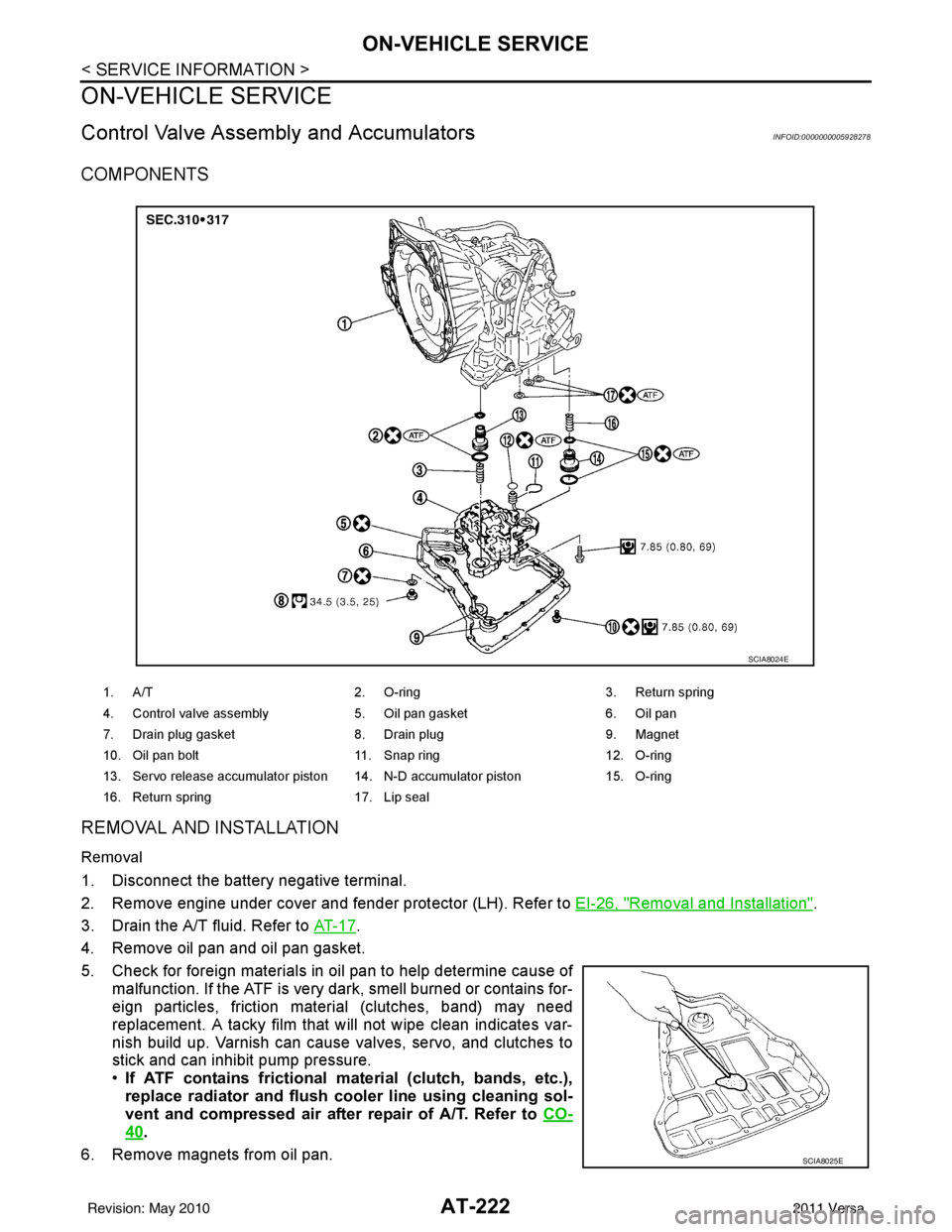
COMPONENTS
REMOVAL AND INSTALLATION
Removal
1. Disconnect the battery negative terminal.
2. Remove engine under cover and fender protector (LH). Refer to EI-26, "
Removal and Installation".
3. Drain the A/T fluid. Refer to AT- 1 7
.
4. Remove oil pan and oil pan gasket.
5. Check for foreign materials in oil pan to help determine cause of malfunction. If the ATF is very dark, smell burned or contains for-
eign particles, friction material (clutches, band) may need
replacement. A tacky film that will not wipe clean indicates var-
nish build up. Varnish can cause valves, servo, and clutches to
stick and can inhibit pump pressure.
•If ATF contains frictional ma terial (clutch, bands, etc.),
replace radiator and flush cool er line using cleaning sol-
vent and compressed air after repair of A/T. Refer to CO-
40.
6. Remove magnets from oil pan.
1. A/T 2. O-ring 3. Return spring
4. Control valve assembly 5. Oil pan gasket6. Oil pan
7. Drain plug gasket 8. Drain plug9. Magnet
10. Oil pan bolt 11. Snap ring 12. O-ring
13. Servo release accumulator piston 14. N-D accumulator piston 15. O-ring
16. Return spring 17. Lip seal
SCIA8024E
SCIA8025E
Revision: May 2010 2011 Versa
Page 252 of 3787
TRANSAXLE ASSEMBLYAT-235
< SERVICE INFORMATION >
DE
F
G H
I
J
K L
M A
B
AT
N
O P
• When replacing an engine or transmission you must make sure any dowels are installed correctly during re-assembly.
• Improper alignment caused by missing dowels may cause vibration, oil leaks or breakage of drive
train components.
• Do not reuse O-rings and copper washers. Refer to "COMPONENTS".
• When turning crankshaft, turn it clockwise as viewed from the front of the engine.
• When tightening the bolts for th e torque converter while securing the crankshaft pulley bolt, be sure
to confirm the tightening torque of the crankshaft pulley bolt. Refer to EM-159
.
• After converter is installed to drive plate, ro tate crankshaft several turns to check that transaxle
rotates freely without binding.
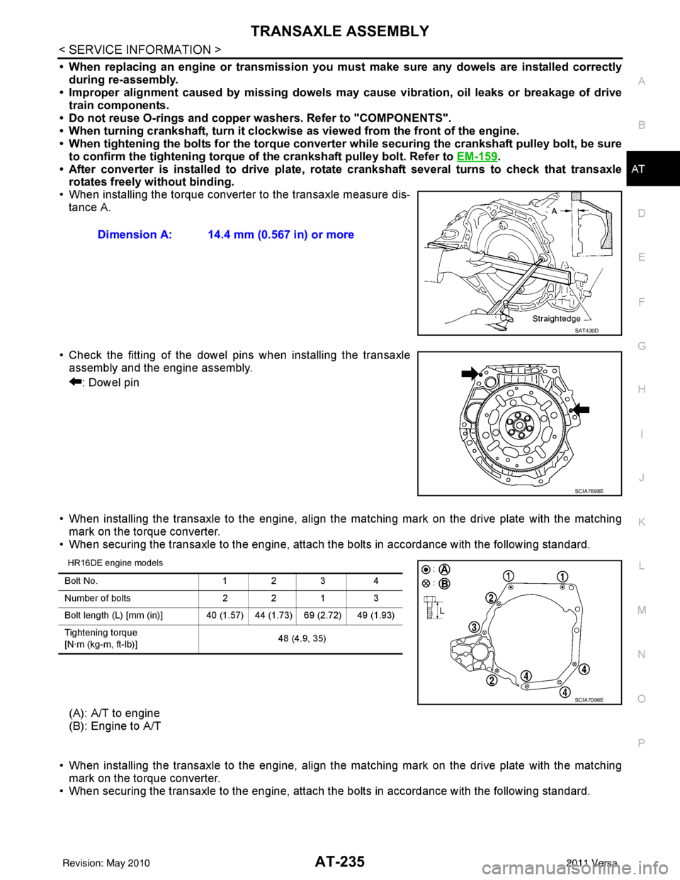
• When installing the torque converter to the transaxle measure dis- tance A.
• Check the fitting of the dowel pins when installing the transaxle assembly and the engine assembly.
: Dowel pin
• When installing the transaxle to the engine, align the matching mark on the drive plate with the matching mark on the torque converter.
• When securing the transaxle to the engine, attach the bolts in accordance with the following standard.
HR16DE engine models
(A): A/T to engine
(B): Engine to A/T
• When installing the transaxle to the engine, align the matching mark on the drive plate with the matching mark on the torque converter.
• When securing the transaxle to the engine, attach the bolts in accordance with the following standard. Dimension A: 14.4 mm (0.567 in) or more
SAT430D
SCIA7698E
Bolt No.
1 2 34
Number of bolts 2 2 13
Bolt length (L) [mm (in)] 40 (1.5 7) 44 (1.73) 69 (2.72) 49 (1.93)
Tightening torque
[N·m (kg-m, ft-lb)] 48 (4.9, 35)
SCIA7096E
Revision: May 2010
2011 Versa
Page 260 of 3787

OVERHAULAT-243
< SERVICE INFORMATION >
DE
F
G H
I
J
K L
M A
B
AT
N
O P
MR18DE ENGINE MODELS
16. Servo release accumulator piston 17. Return spring
18. Control valve assembly
19. Oil pan gasket 20. Oil pan 21. Drain plug gasket
22. Drain plug 23. Magnet 24. Oil pan bolt
25. Snap ring 26. O-ring 27. O-ring
28. N-D accumulator piston 29. Return spring 30. O-ring
31. Lip seal 32. Input speed sensor 33. O-ring
34. Retaining pin 35. Detent spring 36. Retaining pin
37. Manual shaft 38. Manual shaft oil seal 39. Manual plate
40. Parking rod plate 41. Parking rod 42. OD servo piston retainer
43. Snap ring 44. O-ring 45. OD servo piston
46. D-ring 47. Servo release accumulator piston 48. O-ring
49. E-ring 50. Spring retainer 51. OD servo return spring
52. D-ring 53. Band servo piston 54. Band servo thrust washer
55. Band servo piston stem 56. 2nd servo return spring 57. Transmission range switch
58. Parking shaft 59. Return spring 60. Output gear adjusting spac-
er
61. Output gear bearing 62. Output gear 63. Side cover gasket
64. Side cover 65. Side cover bolt 66. Lock nut
67. Idler gear 68. Idler gear bearing 69. Reduction pinion gear ad-
justing shim
70. Parking actuator support 71. Parking pawl 72. LH differential side oil seal
73. Output speed sensor
: Apply Genuine Anaerobic Liquid Gasket or equivalent.
Revision: May 2010 2011 Versa
Page 267 of 3787

AT-250
< SERVICE INFORMATION >
OVERHAUL
Oil Channel
INFOID:0000000005928286
HR16DE ENGINE MODELS
19. Oil pan 20. Drain plug gasket21. Drain plug
22. Magnet 23. Oil pan bolt24. Snap ring
25. O-ring 26. O-ring27. N-D accumulator piston
28. Return spring 29. O-ring 30. Lip seal
31. Input speed sensor 32. O-ring 33. Retaining pin
34. Detent spring 35. Retaining pin 36. Manual shaft
37. Manual shaft oil seal 38. Manual plate 39. Parking rod plate
40. Parking rod 41. OD servo piston retainer42. Snap ring
43. O-ring 44. OD servo piston45. D-ring
46. Servo piston retainer 47. O-ring48. E-ring
49. Spring retainer 50. OD servo return spring 51. D-ring
52. Band servo piston 53. Band servo thrust washer 54. Band servo piston stem
55. 2nd servo return spring 56. Transmission range switch57. Parking shaft
58. Return spring 59. Thrust needle bearing60. Seal ring
61. Output shaft 62. Output shaft bearing63. Output shaft adjusting shim
64. Side cover 65. Side cover bolt 66. Lock nut
67. Idler gear 68. Idler gear bearing69. Reduction pinion gear adjusting
shim
70. Parking actuator support 71. Parking pawl 72. LH differential side oil seal
73. Output speed sensor
: Apply Genuine Anaerobic Liquid Gasket or equivalent.
Revision: May 2010 2011 Versa
Page 280 of 3787
DISASSEMBLYAT-263
< SERVICE INFORMATION >
DE
F
G H
I
J
K L
M A
B
AT
N
O P
25. Remove differential side bearing outer race from transaxle case and converter housing. (MR18DE engine models)
26. Remove differential side bearing adjusting shim from transaxle case.
27. Remove RH differential side oil seal from converter housing using a suitable tool.
CAUTION:
Be careful not to scratch converter housing.
28. Remove differential lubricant tube (1) and clips (2) from con- verter housing.
: Bolt
29. Remove oil pump assembly according to the following procedures. Tool number : KV381054S0 (J-34286)
SCIA5378E
SCIA4938E
SCIA3283E
SCIA7817E
Revision: May 2010
2011 Versa
Page 349 of 3787
AT-332
< SERVICE INFORMATION >
REPAIR FOR COMPONENT PARTS
MR18DE engine models
DISASSEMBLY
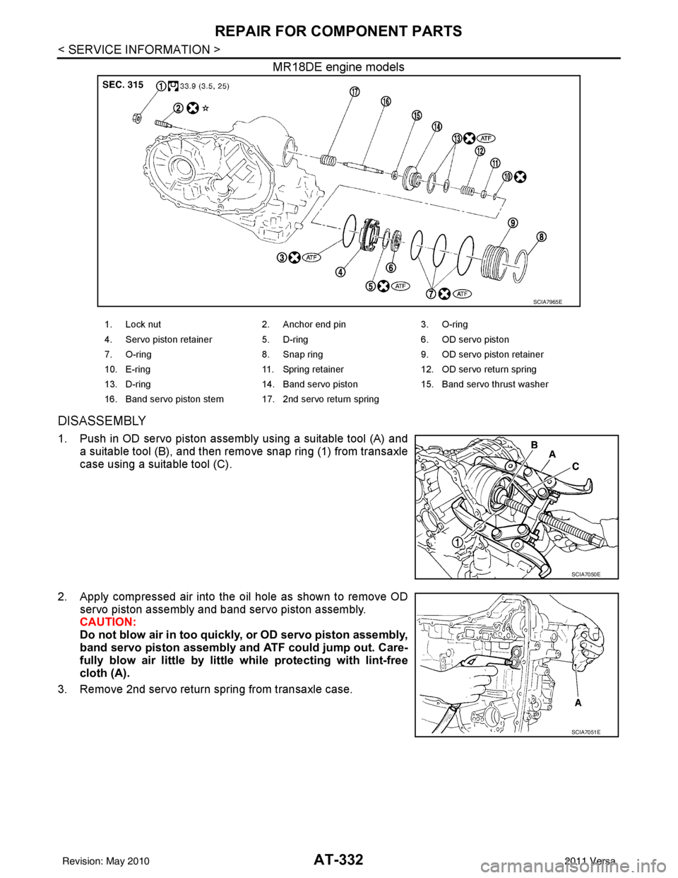
1. Push in OD servo piston assembly using a suitable tool (A) anda suitable tool (B), and then remove snap ring (1) from transaxle
case using a suitable tool (C).
2. Apply compressed air into the oil hole as shown to remove OD servo piston assembly and band servo piston assembly.
CAUTION:
Do not blow air in too quickly, or OD servo piston assembly,
band servo piston assembly and ATF could jump out. Care-
fully blow air little by little while protecting with lint-free
cloth (A).
3. Remove 2nd servo return spring from transaxle case.
SCIA7965E
1. Lock nut 2. Anchor end pin 3. O-ring
4. Servo piston retainer 5. D-ring 6. OD servo piston
7. O-ring 8. Snap ring 9. OD servo piston retainer
10. E-ring 11. Spring retainer 12. OD servo return spring
13. D-ring 14. Band servo piston 15. Band servo thrust washer
16. Band servo piston stem 17. 2nd servo return spring
SCIA7050E
SCIA7051E
Revision: May 2010 2011 Versa
Page 361 of 3787
AT-344
< SERVICE INFORMATION >
ASSEMBLY
ASSEMBLY
Assembly (1)INFOID:0000000005928303
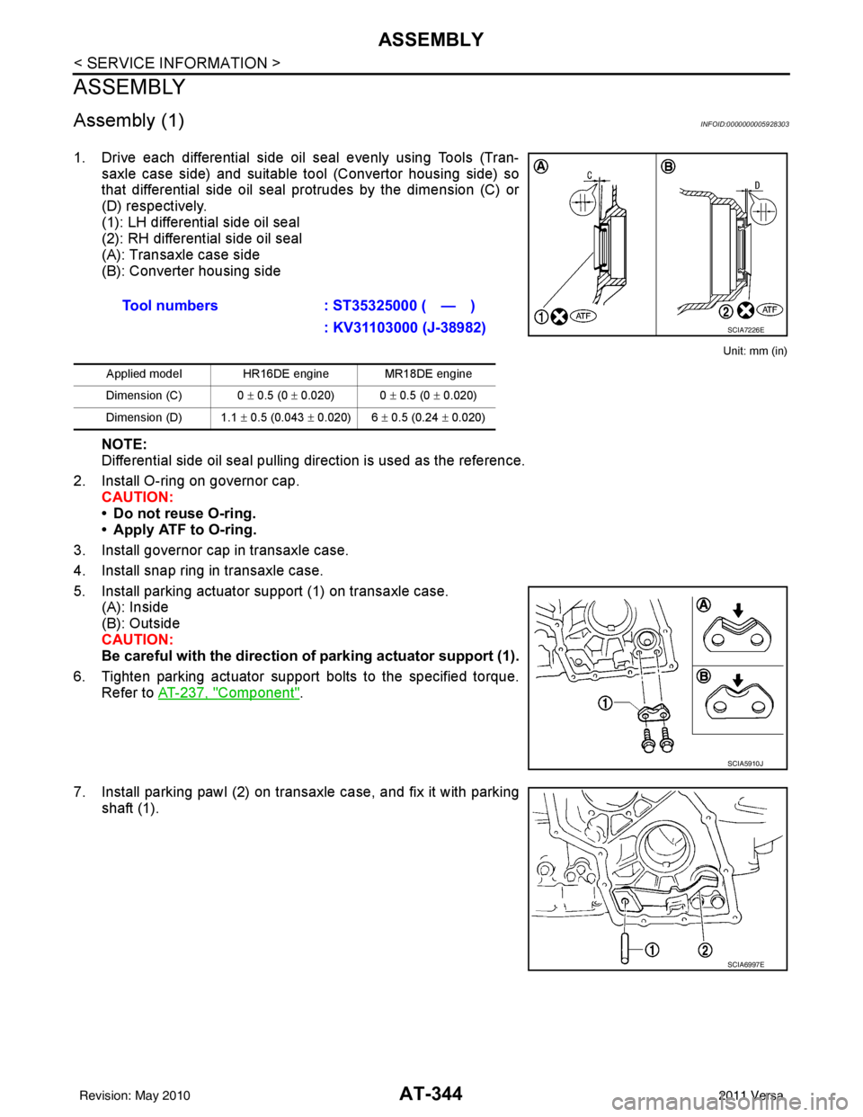
1. Drive each differential side oil seal evenly using Tools (Tran-saxle case side) and suitable tool (Convertor housing side) so
that differential side oil seal protrudes by the dimension (C) or
(D) respectively.
(1): LH differential side oil seal
(2): RH differential side oil seal
(A): Transaxle case side
(B): Converter housing side
Unit: mm (in)
NOTE:
Differential side oil seal pulling direction is used as the reference.
2. Install O-ring on governor cap. CAUTION:
• Do not reuse O-ring.
• Apply ATF to O-ring.
3. Install governor cap in transaxle case.
4. Install snap ring in transaxle case.
5. Install parking actuator support (1) on transaxle case. (A): Inside
(B): Outside
CAUTION:
Be careful with the direction of parking actuator support (1).
6. Tighten parking actuator support bolts to the specified torque. Refer to AT-237, "
Component".
7. Install parking pawl (2) on transaxle case, and fix it with parking shaft (1).Tool numbers
: ST35325000 ( — )
: KV31103000 (J-38982)
Applied model HR16DE engine MR18DE engine
Dimension (C) 0 ± 0.5 (0 ± 0.020) 0 ± 0.5 (0 ± 0.020)
Dimension (D) 1.1 ± 0.5 (0.043 ± 0.020) 6 ± 0.5 (0.24 ± 0.020)
SCIA7226E
SCIA5910J
SCIA6997E
Revision: May 2010 2011 Versa
Page 366 of 3787
ASSEMBLYAT-349
< SERVICE INFORMATION >
DE
F
G H
I
J
K L
M A
B
AT
N
O P
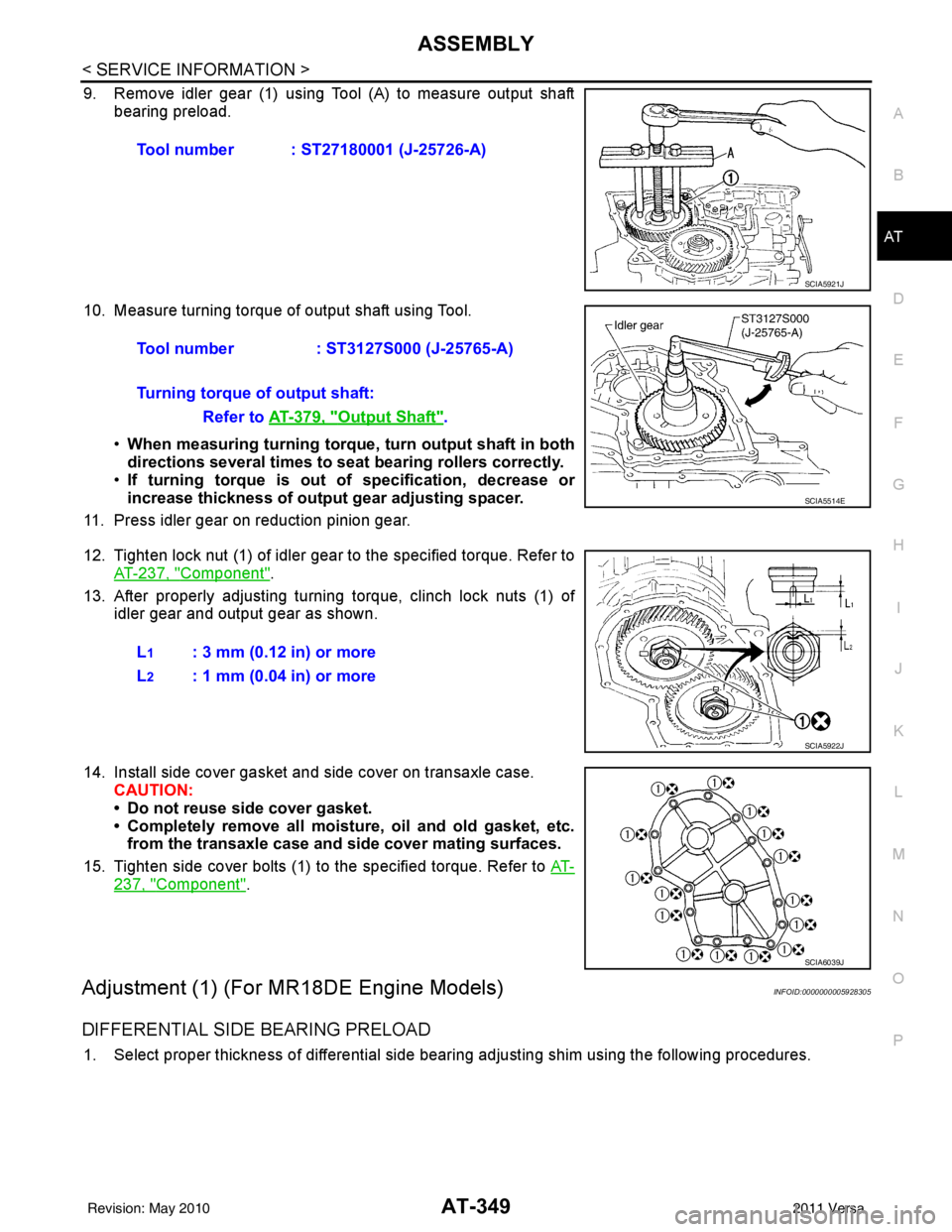
9. Remove idler gear (1) using Tool (A) to measure output shaft bearing preload.
10. Measure turning torque of output shaft using Tool. •When measuring turning torque , turn output shaft in both
directions several times to seat bearing rollers correctly.
• If turning torque is out of specification, decrease or
increase thickness of output gear adjusting spacer.
11. Press idler gear on reduction pinion gear.
12. Tighten lock nut (1) of idler gear to the specified torque. Refer to AT-237, "
Component".
13. After properly adjusting turning torque, clinch lock nuts (1) of idler gear and output gear as shown.
14. Install side cover gasket and side cover on transaxle case. CAUTION:
• Do not reuse side cover gasket.
• Completely remove all moistu re, oil and old gasket, etc.
from the transaxle case and side cover mating surfaces.
15. Tighten side cover bolts (1) to the specified torque. Refer to AT-
237, "Component".
Adjustment (1) (For MR18DE Engine Models)INFOID:0000000005928305
DIFFERENTIAL SIDE BEARING PRELOAD
1. Select proper thickness of differential side bearing adjusting shim using the following procedures.Tool number : ST27180001 (J-25726-A)
SCIA5921J
Tool number
: ST3127S000 (J-25765-A)
Turning torque of output shaft: Refer to AT-379, "
Output Shaft".
SCIA5514E
L1: 3 mm (0.12 in) or more
L
2: 1 mm (0.04 in) or more
SCIA5922J
SCIA6039J
Revision: May 2010 2011 Versa