2011 NISSAN TIIDA cvt
[x] Cancel search: cvtPage 2708 of 3787
GI-4
< SERVICE INFORMATION >
PRECAUTIONS
• Replace oil seals, gaskets, packings, O-rings, locking washers, cotter pins, self-locking nuts, etc. with new
ones.
• Replace inner and outer races of tapered roller bearings and needle bearings as a set.
• Arrange the disassembled parts in accordance with their assembled locations and sequence.
• Do not touch the terminals of electrical com ponents which use microcomputers (such as ECM).
Static electricity may damage internal electronic components.
• After disconnecting vacuum or air hoses, atta ch a tag to indicate the proper connection.
• Use only the fluids and lubricants specified in this manual.
• Use approved bonding agent, sealants or their equivalents when required.
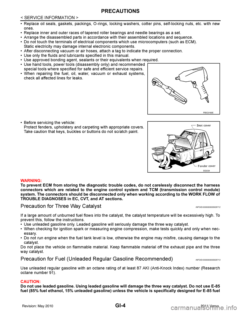
• Use hand tools, power tools (disassembly only) and recommended special tools where specified for safe and efficient service repairs.
• When repairing the fuel, oil, water, vacuum or exhaust systems, check all affected lines for leaks.
• Before servicing the vehicle: Protect fenders, upholstery and carpeting with appropriate covers.
Take caution that keys, buckles or buttons do not scratch paint.
WARNING:
To prevent ECM from storing the diagnostic tro uble codes, do not carelessly disconnect the harness
connectors which are related to the engine control system and TCM (transmission control module)
system. The connectors should be disconnected only when working according to the WORK FLOW of
TROUBLE DIAGNOSES in EC, CVT, and AT sections.
Precaution for Three Way CatalystINFOID:0000000005929712
If a large amount of unburned fuel flows into the catalyst , the catalyst temperature will be excessively high. To
prevent this, follow the instructions.
• Use unleaded gasoline only. Leaded gasoline will seriously damage the three way catalyst.
• When checking for ignition spark or measuring engine compression, make tests quickly and only when nec- essary.
• Do not run engine when the fuel tank level is low, otherwise the engine may misfire, causing damage to the
catalyst.
Do not place the vehicle on flammable material. Keep flammable material off the exhaust pipe and the three
way catalyst.
Precaution for Fuel (Unleade d Regular Gasoline Recommended)INFOID:0000000005929713
Use unleaded regular gasoline with an octane rating of at least 87 AKI (Anti-Knock Index) number (Research
octane number 91).
CAUTION:
Do not use leaded gasoline. Using leaded gasoline will damage the three way catalyst. Do not use E-85
fuel (85% fuel ethanol, 15% unleaded gasoline) unless the vehicle is specifically designed for E-85 fuel
PBIC0190E
SGI234
Revision: May 2010 2011 Versa
Page 2724 of 3787
GI-20
< SERVICE INFORMATION >
HOW TO USE THIS MANUAL
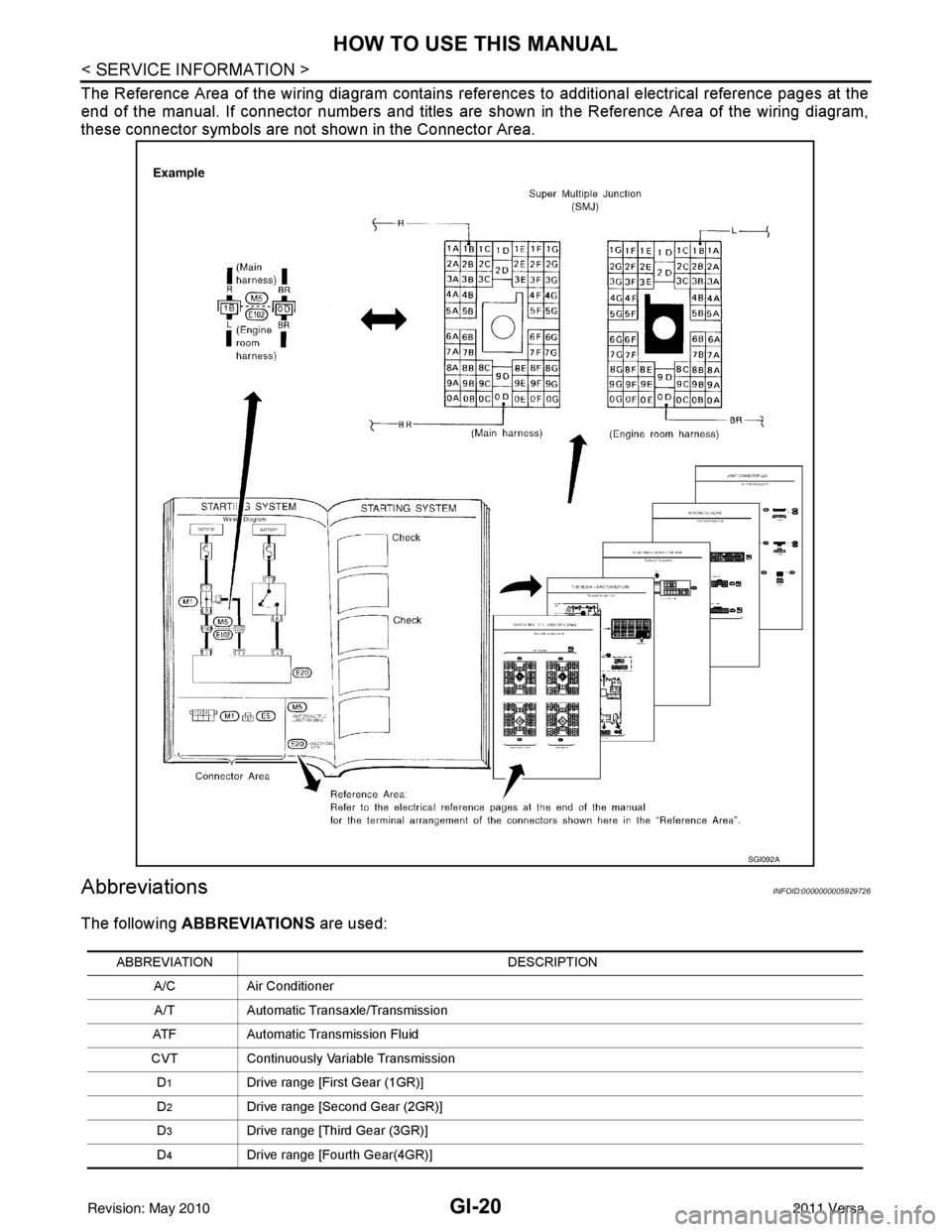
The Reference Area of the wiring diagram contains references to additional electrical reference pages at the
end of the manual. If connector numbers and titles are shown in the Reference Area of the wiring diagram,
these connector symbols are not shown in the Connector Area.
AbbreviationsINFOID:0000000005929726
The following ABBREVIATIONS are used:
SGI092A
ABBREVIATION DESCRIPTION
A/C Air Conditioner
A/T Automatic Transaxle/Transmission
ATF Automatic Transmission Fluid
CVT Continuously Variable Transmission
D
1Drive range [First Gear (1GR)]
D
2Drive range [Second Gear (2GR)]
D
3Drive range [Third Gear (3GR)]
D
4Drive range [Fourth Gear(4GR)]
Revision: May 2010 2011 Versa
Page 2739 of 3787

CONSULT-III CHECKING SYSTEMGI-35
< SERVICE INFORMATION >
C
DE
F
G H
I
J
K L
M B
GI
N
O PCONSULT-III CHECKING SYSTEM
DescriptionINFOID:0000000005929730
• CONSULT-III is a hand-held type tester. When it is connected with a diagnostic connector equipped on the vehicle side, it will communicate with the contro l unit equipped in the vehicle and then enable various kinds
of diagnostic tests.
• Refer to CONSULT-III Operator's Manual for more information.
Function and System ApplicationINFOID:0000000005929731
x: Applicable.
*1: If equipped.
*2: With automatic transmission (A/T).
*3: With continuously variable transmission (CVT). Diagnostic test mode
Function
ENGINE
ABS*
1
AIR BAG EPS
IPDM E/R BCM
METER/M&A
INTELLIGENT KEY*
1
TRANSMISSION*
2
TRANSMISSION*
3
Work Support This mode enables a technician to adjust some devices faster and
more accurately by following indications on CONSULT-III. xx - - - x - - xx
Self Diagnostic Result Self-diagnostic results can be read and erased quickly. x x x x x x x x x x
Data Monitor Input/Output data in the ECU can be read. x x x x x x x x x x
CAN Diagnostic Support
Monitor The communication condition of CAN communication line can be
read.
xx - xxxxxxx
Active Test Diagnostic Test Mode in which CONSULT-III drives actuators apart
from ECU shifting some parameters in a specified range. xx - - xx - x - -
Function Test This mode can show results of self-diagnosis of ECU with either
"OK" or "NG". For engines, more practical tests regarding sensors/
switches and/or actuators are available. xxx - - - - - xx
DTC & SRT Confirmation The results of SRT (System Readiness Test) and the self-diagno-
sis status/result can be confirmed. x---------
Ecu Identification ECM/ECU part number can be read. x x x x - x - x x x
Configuration Sets control module parameters to match vehicle options. - - - - - x - - - -
Special Function Other results or histories, etc that are recorded in ECU are dis-
played. --x-----xx
Revision: May 2010
2011 Versa
Page 2744 of 3787

GI-40
< SERVICE INFORMATION >
TOW TRUCK TOWING
TOW TRUCK TOWING
Tow Truck TowingINFOID:0000000005929736
CAUTION:
• Never tow a CVT model with the rear wheels raised and the front wheels on the ground. This may
cause serious and expensive damage to the transaxle. If it is necessary to tow the vehicle with the
rear wheels raised, always use towi ng dollies under the front wheels.
• Never tow a CVT model from the rear (that is backw ard) with four wheels on the ground. This may
cause serious and expensive damage to the transaxle.
NISSAN recommends that the vehicle be towed with the driving (front) wheels off the ground.
CAUTION:
• Always release the parking brake when towing the veh icle with the front wheels raised with the rear
wheels on the ground.
• When the battery of a vehicle equipped with th e Intelligent Key system is discharged, the vehicle
should be towed with the front wheels on the tow dollies or place the vehicle on a flat bed truck.
CAUTION:
• All applicable local laws regarding the towing operation must be obeyed.
• It is necessary to use proper towi ng equipment to avoid possible damage to the vehicle during tow-
ing operation. To wing is in accordance with Towing Procedure Manual at dealer.
• Always attach safety chains before towing.
• When towing, make sure that the transmission, steering system and power train are in good order. If
any unit is damaged, dollies must be used.
NISSAN recommends that the vehicle be towed with the driving (front) wheels off the ground as illustrated.
TOWING AN AUTOMATIC TRANSAXLE MODEL WITH FOUR WHEELS ON GROUND
CAUTION:
Never tow an automatic transaxle model with four wheels on the ground as this may cause serious
and expensive damage to the transaxle.
Vehicle Recovery (Freeing a Stuck Vehicle)INFOID:0000000005929737
• Tow chains or cables must be attached only to the main structural members of the vehicle.
• Pulling devices should be routed so they do not touch any part of the suspension, steering, brake or cooling
systems.
• Always pull the cable straight out from the front or r ear of the vehicle. Never pull on the vehicle at an angle.
• Pulling devices such as ropes or canvas straps are not recommended for use in vehicle towing or recovery.
WARNING:
• Do not spin the tires at high sp eed. This could cause them to explode and result in serious injury.
Parts of the vehicle could also overheat and be damaged.
• Install removable recovery hook securely using wheel nut wrench.
PIIB6801E
Revision: May 2010 2011 Versa
Page 2747 of 3787

IDENTIFICATION INFORMATIONGI-43
< SERVICE INFORMATION >
C
DE
F
G H
I
J
K L
M B
GI
N
O PIDENTIFICATION INFORMATION
Model VariationINFOID:0000000005929740
Model code designations:
IDENTIFICATION NUMBER
Body Engine Transmission Grade Destination
USA Canada
Hatchback MR18DE 6 M/T
SFDSALDY-EUA
FDSALDY-ENA
4 A/T FDSALDA-EUAFDSALDA-ENA
6 M/T SL —
FDSALGY-ENA
CVT FDSALGZ-EUAFDSALGZ-ENA
Sedan 6 M/T
SBDSALDY-EUA
—
4 A/T BDSALDA-EUA—
4 A/T SLBDSALGA-EUA —
HR16DE 5 M/T
Base
BDTALAF-EUA BDTALAF-ENA
1.6 L BDTALCF-EUA —
4 A/T 1.6 L
BDTALCA-EUA —
Base —BDTALAA-ENA
Position (Left to Right) Character
Qualifier Definition
1 F Body type F: Hatchback
B: Sedan
2 DS Engine DS: MR18DE (1.8L)
DT: HR16DE (1.6L)
3
4 A Axle A: 2WD model
5 L Handle L: LH drive
6DG ra de A: 1.6 Base
C: 1.6
D: 1.8 S
G: 1.8 SL
7 Y Transmission A: 4 A/T
F: 5 M/T
Y: 6 M/ T
Z: CVT
8 C11 Model C11: Versa
9
10 11 E Intake E: EGI
12 U Zone N: Canada
U: USA
13 A Equipment A: Standard
14
xxxxx Option Codes Option Codes
15
16
17
18
Revision: May 2010
2011 Versa
Page 2750 of 3787
GI-46
< SERVICE INFORMATION >
IDENTIFICATION INFORMATION
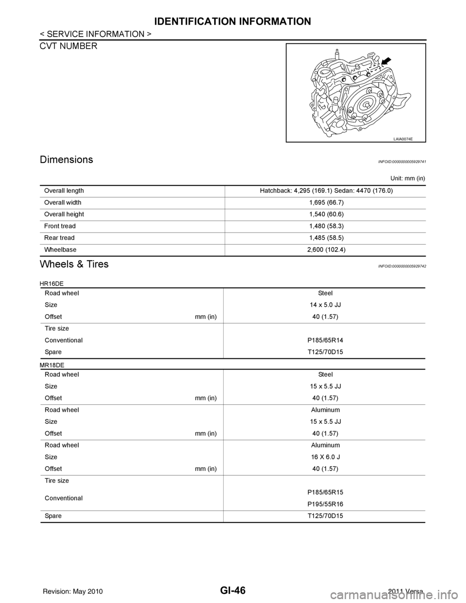
CVT NUMBER
DimensionsINFOID:0000000005929741
Unit: mm (in)
Wheels & TiresINFOID:0000000005929742
HR16DE
MR18DE
LAIA0074E
Overall lengthHatchback: 4,295 (169.1) Sedan: 4470 (176.0)
Overall width 1,695 (66.7)
Overall height 1,540 (60.6)
Front tread 1,480 (58.3)
Rear tread 1,485 (58.5)
Wheelbase 2,600 (102.4)
Road wheel St ee l
Size 14 x 5.0 JJ
Offset mm (in)40 (1.57)
Tire size
Conventional P185/65R14
Spare T125/70D15
Road wheel St ee l
Size 15 x 5.5 JJ
Offset mm (in)40 (1.57)
Road wheel Aluminum
Size 15 x 5.5 JJ
Offset mm (in)40 (1.57)
Road wheel Aluminum
Size 16 X 6.0 J
Offset mm (in)40 (1.57)
Tire size
Conventional P185/65R15
P195/55R16
Spare T125/70D15
Revision: May 2010 2011 Versa
Page 2827 of 3787
IP-6
< SYMPTOM DIAGNOSIS >
SQUEAK AND RATTLE TROUBLE DIAGNOSES
If possible, drive the vehicle with the customer until the noise is duplicated. Note any additional information on
the Diagnostic Worksheet regarding the conditions or lo cation of the noise. This information can be used to
duplicate the same conditions when you confirm the repair.
If the noise can be duplicated easily during the test drive, to help identify the source of the noise, try to dupli-
cate the noise with the vehicle stopped by doing one or all of the following:
1. Close a door.
2. Tap or push/pull around the area where the noise appears to be coming from.
3. Rev the engine.
4. Use a floor jack to recreate vehicle “twist”.
5. At idle, apply engine load (electrical load, half-clutch on M/T model, drive position on CVT and A/T mod-
els).
6. Raise the vehicle on a hoist and hit a tire with a rubber hammer.
• Drive the vehicle and attempt to duplicate the conditions the customer states exist when the noise occurs.
• If it is difficult to duplicate the noise, drive the v ehicle slowly on an undulating or rough road to stress the
vehicle body.
CHECK RELATED SERVICE BULLETINS
After verifying the customer concern or symptom, chec k ASIST for Technical Service Bulletins (TSBs) related
to that concern or symptom.
If a TSB relates to the symptom, follo w the procedure to repair the noise.
LOCATE THE NOISE AND IDENTIFY THE ROOT CAUSE
1. Narrow down the noise to a general area. To help pi npoint the source of the noise, use a listening tool
(Chassis Ear: J-39570, Engine Ear: J-39565, and mechanics stethoscope).
2. Narrow down the noise to a more specific area and identify the cause of the noise by: • Removing the components in the area that you suspect the noise is coming from.
Do not use too much force when removing clip s and fasteners, otherwise clips and fasteners
can be broken or lost during the repair , resulting in the creation of new noise.
• Tapping or pushing/pulling the component that you suspect is causing the noise.
Do not tap or push/pull the component with excessive force, otherwise the noise will be elimi-
nated only temporarily.
• Feeling for a vibration with your hand by touching the component(s) that you suspect is (are) causing
the noise.
• Placing a piece of paper between components that you suspect are causing the noise.
• Looking for loose components and contact marks.
Refer to IP-7, "
Generic Squeak and Rattle Troubleshooting".
REPAIR THE CAUSE
• If the cause is a loose component, tighten the component securely.
• If the cause is insufficient clearance between components:
- Separate components by repositioning or loosening and retightening the component, if possible.
- Insulate components with a suitable insulator such as urethane pads, foam blocks, felt cloth tape or ure-
thane tape. A NISSAN Squeak and Rattle Kit (J-43980) is available through your authorized NISSAN Parts
Department.
CAUTION:
Do not use excessive force as many components are constructed of plastic and may be damaged.
Always check with the Parts Department for the latest parts information.
The following materials are contained in the NISSAN Squeak and Rattle Kit (J-43980). Each item can be
ordered separately as needed.
URETHANE PADS [1.5 mm (0.059 in) thick]
Insulates connectors, harness, etc.
76268-9E005: 100 x 135 mm (3.94 x 5.31 in)/76884-71L01: 60 x 85 mm (2.36 x 3.35 in)/76884-71L02: 15 x 25
mm (0.59 x 0.98 in)
INSULATOR (Foam blocks)
Insulates components from contact. Can be used to fill space behind a panel.
73982-9E000: 45 mm (1.77 in) thick, 50 x 50 mm (1.97 x 1.97 in)/73982-50Y00: 10 mm (0.39 in) thick, 50 x 50
mm (1.97 x 1.97 in)
INSULATOR (Light foam block)
80845-71L00: 30 mm (1.18 in) thick, 30 x 50 mm (1.18 x 1.97 in)
FELT CLOTH TAPE
Used to insulate where movement does not occu r. Ideal for instrument panel applications.
Revision: May 2010 2011 Versa
Page 2833 of 3787
IP-12
< ON-VEHICLE REPAIR >
INSTRUMENT PANEL ASSEMBLY
Removal and Installation
INFOID:0000000005929593
CAUTION:
• Disconnect both the negative and positive battery terminals, then wait at least three minutes.
• Never tamper with or force air bag lid open, as this may adversely affect air bag performance.
• Be careful not to scratch pad and other parts.
INSTRUMENT PANEL ASSEMBLY
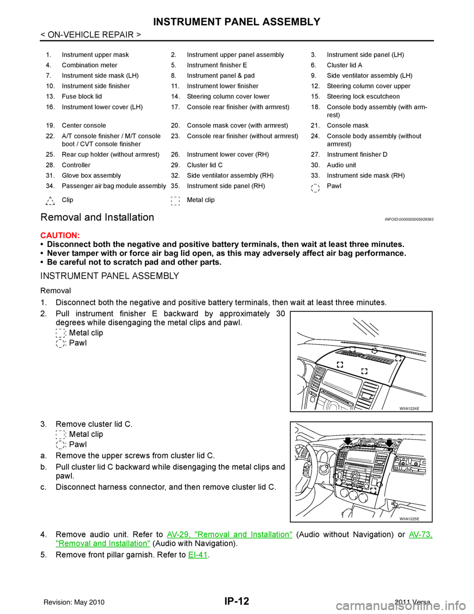
Removal
1. Disconnect both the negative and positive battery terminals, then wait at least three minutes.
2. Pull instrument finisher E backward by approximately 30
degrees while disengaging the metal clips and pawl.
: Metal clip
: Pawl
3. Remove cluster lid C. : Metal clip
: Pawl
a. Remove the upper screws from cluster lid C.
b. Pull cluster lid C backward while disengaging the metal clips and pawl.
c. Disconnect harness connector, and then remove cluster lid C.
4. Remove audio unit. Refer to AV-29, "
Removal and Installation" (Audio without Navigation) or AV-73,
"Removal and Installation" (Audio with Navigation).
5. Remove front pillar garnish. Refer to EI-41
.
1. Instrument upper mask 2. Instrument upper panel assembly 3. Instrument side panel (LH)
4. Combination meter 5. Instrument finisher E 6. Cluster lid A
7. Instrument side mask (LH) 8. Instrument panel & pad 9. Side ventilator assembly (LH)
10. Instrument side finisher 11. Instrument lower finisher 12. Steering column cover upper
13. Fuse block lid 14. Steering column cover lower 15. Steering lock escutcheon
16. Instrument lower cover (LH) 17. Console rear finisher (with armrest) 18. Console body assembly (with arm- rest)
19. Center console 20. Console mask cover (with armrest) 21. Console mask
22. A/T console finisher / M/T console boot / CVT console finisher 23. Console rear finisher (without armrest) 24. Console body assembly (without
armrest)
25. Rear cup holder (without armrest) 26. Instrument lower cover (RH) 27. Instrument finisher D
28. Controller 29. Cluster lid C 30. Audio unit
31. Glove box assembly 32. Side ventilator assembly (RH) 33. Instrument side mask (RH)
34. Passenger air bag module assembly 35. Instrument side panel (RH) Pawl
Clip Metal clip
WIIA1224E
WIIA1225E
Revision: May 2010 2011 Versa