2011 NISSAN TIIDA seat adjustment
[x] Cancel search: seat adjustmentPage 3564 of 3787
COIL SPRINGRSU-11
< SERVICE INFORMATION >
C
DF
G H
I
J
K L
M A
B
RSU
N
O P
COIL SPRING
Removal and InstallationINFOID:0000000005931089
REMOVAL
1. Remove wheel and tire using power tool.
2. Remove wheel sensor from wheel hub and bearing assembly. Refer to BRC-33, "
Removal and Installa-
tion".
CAUTION:
Do not pull on wheel sensor harness.
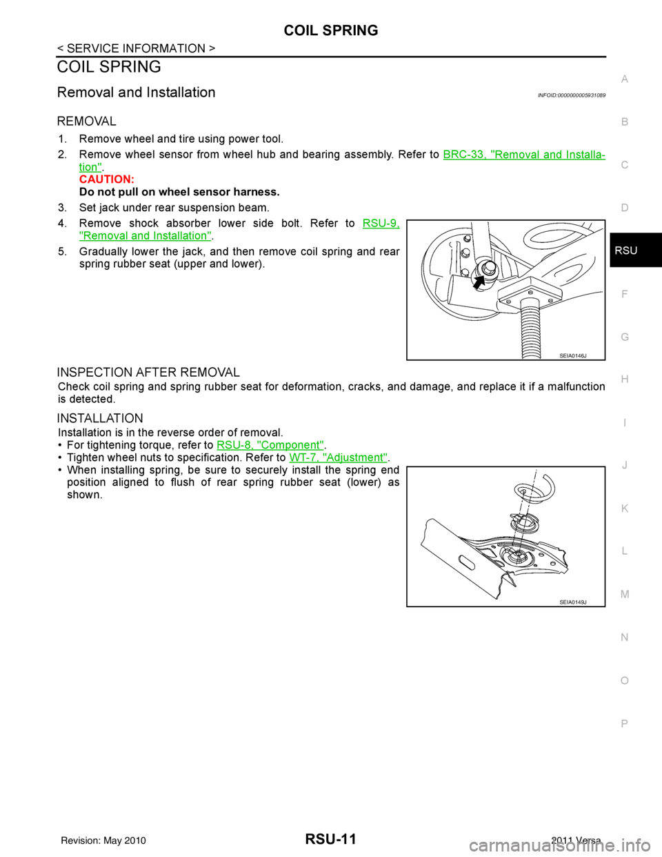
3. Set jack under rear suspension beam.
4. Remove shock absorber lower side bolt. Refer to RSU-9,
"Removal and Installation".
5. Gradually lower the jack, and then remove coil spring and rear spring rubber seat (upper and lower).
INSPECTION AFTER REMOVAL
Check coil spring and spring rubber seat for deformation, cracks, and damage, and replace it if a malfunction
is detected.
INSTALLATION
Installation is in the reverse order of removal.
• For tightening torque, refer to RSU-8, "
Component".
• Tighten wheel nuts to specification. Refer to WT-7, "
Adjustment".
• When installing spring, be sure to securely install the spring end position aligned to flush of rear spring rubber seat (lower) as
shown.
SEIA0146J
SEIA0149J
Revision: May 2010 2011 Versa
Page 3613 of 3787

SE-8
< SERVICE INFORMATION >
SQUEAK AND RATTLE TROUBLE DIAGNOSES
Most of these incidents can be repaired by adjusting, securing or insulating the item(s) or component(s) caus-
ing the noise.
SUNROOF/HEADLINING
Noises in the sunroof/headlining area c an often be traced to one of the following:
1. Sunroof lid, rail, linkage or seals making a rattle or light knocking noise
2. Sun visor shaft shaking in the holder
3. Front or rear windshield touching headliner and squeaking
Again, pressing on the components to stop the noise while duplicating the conditions can isolate most of these
incidents. Repairs usually consist of insulating with felt cloth tape.
OVERHEAD CONSOLE (FRONT AND REAR)
Overhead console noises are often caused by the c onsole panel clips not being engaged correctly. Most of
these incidents are repaired by pushing up on the c onsole at the clip locations until the clips engage.
In addition look for:
1. Loose harness or harness connectors.
2. Front console map/reading lamp lense loose.
3. Loose screws at console attachment points.
SEATS
When isolating seat noise it's important to note the pos ition the seat is in and the load placed on the seat when
the noise is present. These conditions should be duplicated when verifying and isolating the cause of the
noise.
Cause of seat noise include:
1. Headrest rods and holder
2. A squeak between the seat pad cushion and frame
3. The rear seatback lock and bracket
These noises can be isolated by moving or pressing on the suspected components while duplicating the con-
ditions under which the noise occurs. Most of thes e incidents can be repaired by repositioning the component
or applying urethane tape to the contact area.
UNDERHOOD
Some interior noise may be caused by components under the hood or on the engine wall. The noise is then
transmitted into the passenger compartment.
Causes of transmitted underhood noise include:
1. Any component mounted to the engine wall
2. Components that pass through the engine wall
3. Engine wall mounts and connectors
4. Loose radiator mounting pins
5. Hood bumpers out of adjustment
6. Hood striker out of adjustment
These noises can be difficult to isolate since they cannot be reached from the interior of the vehicle. The best
method is to secure, move or insulate one component at a time and test drive the \
vehicle. Also, engine RPM
or load can be changed to isolate the noise. Repairs can usually be made by moving, adjusting, securing, or
insulating the component causing the noise.
Revision: May 2010 2011 Versa
Page 3719 of 3787

WT-1
SUSPENSION
C
DF
G H
I
J
K L
M
SECTION WT
A
B
WT
N
O PCONTENTS
ROAD WHEELS & TIRES
SERVICE INFORMATION .. ..........................2
PRECAUTIONS .............................................. .....2
Precaution for Supplemental Restraint System
(SRS) "AIR BAG" and "SEAT BELT PRE-TEN-
SIONER" ............................................................. ......
2
Precaution Necessary for Steering Wheel Rota-
tion After Battery Disconnect ............................... ......
2
PREPARATION ...................................................4
Special Service Tool ........................................... ......4
Commercial Service Tool ..........................................4
NOISE, VIBRATION AND HARSHNESS
(NVH) TROUBLESHOOTING .............................
5
NVH Troubleshooting Chart ................................ ......5
ROAD WHEEL ....................................................6
Inspection ............................................................ ......6
ROAD WHEEL TIRE ASSEMBLY ......................7
Adjustment .......................................................... ......7
TIRE PRESSURE MONITORING SYSTEM ........9
System Component ............................................. ......9
System Description ...................................................9
CAN COMMUNICATION ....................................11
System Description ............................................. ....11
TROUBLE DIAGNOSES ....................................12
Wiring Diagram- T/WARN - .....................................12
Terminal and Reference Value for BCM .................12
ID Registration Procedure .......................................13
Transmitter Wake Up Operation .............................14
CONSULT-III Function (BCM) .................................14
How to Perform Trouble Diagnosis for Quick and
Accurate Repair ................................................... ....
15
Preliminary Check ...................................................16
Self-Diagnosis (With CONSULT-III) ........................16
Self-Diagnosis (Without CONSULT-III) ...................17
TROUBLE DIAGNOSIS FOR SELF-DIAG-
NOSTIC ITEMS .................................................
20
Data from Transmitter Not Being Received .............20
Transmitter Malfunction ...........................................20
Transmitter Pressure Malfunction ............................21
Vehicle Speed Signal .......................................... ....21
Vehicle Ignition Signal .............................................22
TROUBLE DIAGNOSIS FOR SYMPTOMS ......23
Low Tire Pressure Warning Lamp Does Not Come
On When Ignition Switch Is Turned On ...................
23
Low Tire Pressure Warning Lamp Stays On When
Ignition Switch Is Turned On ............................... ....
23
Low Tire Pressure Warning Lamp Flashes When
Ignition Switch Is Turned On ...................................
24
Hazard Warning Lamps Flash When Ignition
Switch Is Turned On ................................................
25
ID Registration Cannot Be Completed ....................25
REMOVAL AND INSTALLATION .....................26
Transmitter (Pressure Sens or) ................................26
SERVICE DATA AND SPECIFICATIONS
(SDS) .................................................................
28
Road Wheel ......................................................... ....28
Tire ..........................................................................28
Revision: May 2010 2011 Versa
Page 3747 of 3787

WW-1
ELECTRICAL
C
DE
F
G H
I
J
L
M
SECTION WW
A
B
WW
N
O P
CONTENTS
WIPER, WASHER & HORN
SERVICE INFORMATION .. ..........................2
PRECAUTION ................................................ .....2
Precaution for Supplemental Restraint System
(SRS) "AIR BAG" and "SEAT BELT PRE-TEN-
SIONER" ............................................................. ......
2
Precaution Necessary for Steering Wheel Rota-
tion After Battery Disconnect ............................... ......
2
Precaution for Procedure without Cowl Top Cover ......3
PREPARATION ...................................................4
Special Service Tool ........................................... ......4
FRONT WIPER AND WASHER SYSTEM ..........5
Component Parts and Harness Connector Loca-
tion ...................................................................... ......
5
System Description ...................................................5
CAN Communication System Description .................7
Schematic .................................................................8
Wiring Diagram - WIPER - ........................................9
Terminal and Reference Value for BCM .................12
Terminal and Reference Value for IPDM E/R .........12
How to Proceed with Trouble Diagnosis .................12
Preliminary Check ...................................................12
CONSULT-III Function (BCM) .................................12
CONSULT-III Function (IPDM E/R) .........................13
Front Wiper Does Not Operate ...............................14
Front Wiper Does Not Return to Stop Position (Af-
ter Front Wiper Operates for 10 Seconds, They
Stop for 20 Seconds, and After Repeating the Op-
eration Five Times, They Become Inoperative) ......
16
Only Front Wiper Low Does Not Operate ...............17
Only Front Wiper High Does Not Operate ...............18
Only Front Wiper Intermittent Does Not Operate ....19
Front Wiper Intermittent Operation Switch Posi-
tion Cannot Be Adjusted .........................................
20
Wiper Does Not Wipe When Front Washer Oper-
ates .........................................................................
20
Front Wiper Does Not Stop .....................................20
Removal and Installation of Front Wiper Arms ........20
Adjustment of Wiper Arm Stop Location .............. ....21
Removal and Installation of Front Wiper Drive As-
sembly .....................................................................
22
Removal and Installation of Front Washer Nozzle ....22
Inspection for Washer Nozzle ..................................23
Washer Nozzle Adjustment ................................. ....24
Washer Tube Layout ...............................................24
Removal and Installation of Front Wiper and
Washer Switch .........................................................
25
Inspection of Front Wiper and Washer Switch Cir-
cuit ...........................................................................
25
Removal and Installation of Washer Tank ...............25
Removal and Installation of Front Washer Motor ....26
REAR WIPER AND WASHER SYSTEM ..........27
Component Parts and Harness Connector Loca-
tion ....................................................................... ....
27
System Description ..................................................27
Wiring Diagram - WIP/R - ........................................29
Terminal and Reference Value for BCM ..................31
How to Proceed with Trou ble Diagnosis ..................31
Preliminary Check ............................................... ....31
CONSULT-III Function (BCM) .................................31
Rear Wiper Does Not Operate ............................ ....31
Rear Wiper Stop Position Is Incorrect .....................33
Only Rear Wiper Does Not Operate ........................34
Only Rear Wiper Intermittent Does Not Operate .....34
Wiper Does Not Wipe When Rear Washer Oper-
ates ..........................................................................
34
Removal and Installation .........................................34
Washer Nozzle Adjustment .....................................37
POWER SOCKET .............................................38
Wiring Diagram - P/SCKT - .....................................38
Removal and Installation .........................................38
HORN ................................................................40
Wiring Diagram - HORN - ........................................40
Removal and Installation .........................................40
Revision: May 2010 2011 Versa