2011 NISSAN TIIDA Cruis speed control
[x] Cancel search: Cruis speed controlPage 16 of 3787
ACS-1
ELECTRICAL
C
DE
F
G H
I
J
L
M
SECTION ACS
A
B
ACS
N
O P
CONTENTS
AUTO CRUISE CONTROL SYSTEM
SERVICE INFORMATION .. ..........................2
AUTOMATIC SPEED CONTROL DEVICE
(ASCD) ........................................................... .....
2
Precaution for Supplemental Restraint System
(SRS) "AIR BAG" and "SEAT BELT PRE-TEN-
SIONER" ............................................................. .....
2
Description ................................................................2
Revision: May 2010 2011 Versa
Page 18 of 3787
AT-1
TRANSMISSION/TRANSAXLE
DE
F
G H
I
J
K L
M
SECTION AT
A
B
AT
N
O P
CONTENTS
AUTOMATIC TRANSAXLE
SERVICE INFORMATION .. ..........................5
INDEX FOR DTC ............................................ .....5
Alphabetical Index ............................................... ......5
DTC No. Index ..........................................................5
PRECAUTIONS ...................................................7
Precaution for Supplemental Restraint System
(SRS) "AIR BAG" and "SEAT BELT PRE-TEN-
SIONER" ............................................................. ......
7
Precaution Necessary for Steering Wheel Rota-
tion After Battery Disconnect ............................... ......
7
Precaution for On Board Diagnosis (OBD) System
of A/T and Engine .....................................................
8
Precaution .................................................................8
Service Notice or Precaution .....................................9
PREPARATION ..................................................11
Special Service Tool ........................................... ....11
Commercial Service Tool ........................................14
A/T FLUID ...........................................................17
Checking A/T Fluid ..................................................17
Changing A/T Fluid .................................................17
A/T Fluid Cooler Cleaning .......................................18
A/T CONTROL SYSTEM ....................................21
Cross-Sectional View ..............................................21
Shift Mechanism .................................................. ....22
TCM Function ..........................................................30
CAN Communication ...............................................31
Input/Output Signal of TCM .....................................31
Line Pressure Control .............................................32
Shift Control ........................................................ ....33
Lock-up Control .......................................................34
Engine Brake Control (Overrun Clutch Control) ......35
Control Valve ....................................................... ....37
Centrifugal Cancel Mechanism ...............................37
ON BOARD DIAGNOSTIC (OBD) SYSTEM ......39
Introduction ......................................................... ....39
OBD-II Function for A/T System ..............................39
One or Two Trip Detection Logic of OBD-II ......... ....39
OBD-II Diagnostic Trouble Code (DTC) ..................39
Malfunction Indicator Lamp (MIL) ............................41
TROUBLE DIAGNOSIS ....................................42
DTC Inspection Priority Chart ..................................42
Fail-Safe ..................................................................42
How to Perform Trouble Diagnosis for Quick and
Accurate Repair .......................................................
43
A/T Electrical Parts Location ...................................49
Circuit Diagram ........................................................50
Inspections Before Trouble Diagnosis .....................51
Road Test ................................................................55
Check Before Engine Is Started ..............................56
Check at Idle ............................................................56
Cruise Test - Part 1 .................................................58
Cruise Test - Part 2 .................................................61
Cruise Test - Part 3 .................................................62
Vehicle Speed at Which Gear Shifting Occurs ........64
Vehicle Speed at Which Lock-up Occurs/Releas-
es .............................................................................
64
Symptom Chart ........................................................65
TCM Terminal and Reference Value .......................75
CONSULT-III Function (TRANSMISSION) .......... ....77
Diagnosis Procedure without CONSULT-III ............82
U1000 CAN COMM CIRCUIT ...........................87
Description ........................................................... ....87
On Board Diagnosis Logic .......................................87
Possible Cause ........................................................87
DTC Confirmation Procedure ..................................87
Wiring Diagram - AT - CAN .....................................88
Diagnosis Procedure ...............................................89
P0705 TRANSMISSION RANGE SWITCH A ...90
Description ...............................................................90
CONSULT-III Reference Value in Data Monitor
Mode .................................................................... ....
90
On Board Diagnosis Logic .......................................90
Possible Cause ........................................................90
DTC Confirmation Procedure ..................................90
Revision: May 2010 2011 Versa
Page 65 of 3787

AT-48
< SERVICE INFORMATION >
TROUBLE DIAGNOSIS
4. 4-3. “Cruise Test”AT- 5 8
Part 1
�†AT- 1 8 7 , "
Vehicle Cannot Be Started from D1" .
�† AT- 1 8 9 , "
A/T Does Not Shift: D1→ D2or Does Not Kickdown: D4→ D2" .
�† AT- 1 9 0 , "
A/T Does Not Shift: D2→ D3" .
�† AT- 1 9 2 , "
A/T Does Not Shift: D3→ D4" .
�† AT- 1 9 3 , "
A/T Does Not Perform Lock-up" .
�† AT- 1 9 4 , "
A/T Does Not Hold Lock-up Condition" .
�† AT- 1 9 5 , "
Lock-up Is Not Released" .
�† AT- 1 9 6 , "
Engine Speed Does Not Return to Idle (Light Braking D4→ D3)" .
Part 2 AT- 6 1
�†AT- 1 8 7 , "Vehicle Cannot Be Started from D1" .
�† AT- 1 8 9 , "
A/T Does Not Shift: D1→ D2or Does Not Kickdown: D4→ D2" .
�† AT- 1 9 0 , "
A/T Does Not Shift: D2→ D3" .
�† AT- 1 9 2 , "
A/T Does Not Shift: D3→ D4" .
Part 3 AT- 6 2
�†AT- 1 9 7 , "A/T Does Not Shift: D4→ D3, When OD OFF" .
�† AT- 1 9 8 , "
A/T Does Not Shift: D3→ 22, When Selector Lever "D" → "2" Position" .
�† AT- 1 9 9 , "
A/T Does Not Shift: 22→ 11, When Selector Lever "2" → "1" Position" .
�† AT- 2 0 1 , "
Vehicle Does Not Decelerate by Engine Brake" .
�† Perform self-diagnosis. Enter checks for detected items. AT- 7 7
, AT- 8 2 .
�† CAN COMM CIRCUIT AT- 8 7
.
�† TRANSMISSION RANGE SWITCH A AT- 9 0
.
�† TRANSMISSION FLUID TEMPERATURE SENSOR A AT- 9 5
.
�† OUTPUT SPEED SENSOR AT- 1 0 0
.
�† ENGINE SPEED AT- 1 0 5
.
�† 1GR INCORRECT RATIO AT- 1 0 9
�† 2GR INCORRECT RATIO AT- 11 2 .
�† 3GR INCORRECT RATIO AT- 11 5
.
�† 4GR INCORRECT RATIO AT- 11 8
.
�† TORQUE CONVERTER AT-123
.
�† TORQUE CONVERTER AT-128
.
�† PRESSURE CONTROL SOLENOID A AT- 1 3 3
.
�† SHIFT SOLENOID A AT- 1 3 8
.
�† SHIFT SOLENOID B AT- 1 4 3
.
�† OVERRUN CLUTCH SOLENOID AT- 1 4 8
.
�† VEHICLE SPEED SIGNAL AT- 1 5 3
.
�† BATT/FLUID TEMP SEN AT-156
.
�† INPUT SPEED SENSOR A AT- 1 6 2
.
�† CONTROL UNIT (RAM), CONTROL UNIT (ROM) AT-167
.
�† MAIN POWER SUPPLY AND GROUND CIRCUIT AT- 1 6 8
.
5. �† For self-diagnosis NG items, inspect each component. Repair or replace the damaged parts. AT- 7 7
,
AT- 8 2
6. �† Perform “Road Test”. AT- 5 5
7.�† Perform the Diagnostic Procedures for all remaining items marked NG. Repair or replace the damaged parts.
Refer to the Symptom Chart when you perform the procedures. (The chart also shows some other possible symp-
toms and the component inspection orders.) AT- 6 5
8.
�† Erase DTC from TCM and ECM memories. AT- 3 9,
AT- 8 2
Revision: May 2010 2011 Versa
Page 72 of 3787
TROUBLE DIAGNOSISAT-55
< SERVICE INFORMATION >
DE
F
G H
I
J
K L
M A
B
AT
N
O P
Line Pressure
Judgement of Line Pressure Test
Road TestINFOID:0000000005928095
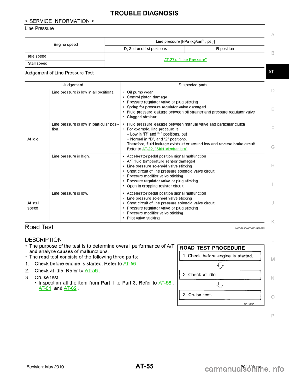
DESCRIPTION
• The purpose of the test is to det
ermine overall performance of A/T
and analyze causes of malfunctions.
• The road test consists of the following three parts:
1. Check before engine is started. Refer to AT- 5 6
.
2. Check at idle. Refer to AT- 5 6
.
3. Cruise test • Inspection all the item from Part 1 to Part 3. Refer to AT- 5 8
,
AT- 6 1
and AT- 6 2 .
Engine speed Line pressure [kPa (kg/cm
2 , psi)]
D, 2nd and 1st positions R position
Idle speed AT- 3 7 4 , "
Line Pressure"Sta ll sp ee d
JudgementSuspected parts
At idle Line pressure is low in all positions. • Oil pump wear
• Control piston damage
• Pressure regulator valve or plug sticking
• Spring for pressure regulator valve damaged
• Fluid pressure leakage between oil strainer and pressure regulator valve
• Clogged strainer
Line pressure is low in particular posi-
tion. • Fluid pressure leakage between manual valve and particular clutch
• For example, line pressure is:
− Low in “R” and “1 ” positions, but
− Normal in “D”, and “2” positions.
Therefore, fluid leakage exists at or around low and reverse brake circuit.
Refer to AT- 2 2 , "
Shift Mechanism".
Line pressure is high. • Accelerator pedal position signal malfunction
• A/T fluid temperature sensor damaged
• Line pressure solenoid valve sticking
• Short circuit of line pressure solenoid valve circuit
• Pressure modifier valve sticking
• Pressure regulator valve or plug sticking
• Open in dropping resistor circuit
At stall
speed Line pressure is low.
• Accelerator pedal position signal malfunction
• Line pressure solenoid valve sticking
• Short circuit of line pressure solenoid valve circuit
• Pressure regulator valve or plug sticking
• Pressure modifier valve sticking
• Pilot valve sticking
SAT786A
Revision: May 2010 2011 Versa
Page 78 of 3787

TROUBLE DIAGNOSISAT-61
< SERVICE INFORMATION >
DE
F
G H
I
J
K L
M A
B
AT
N
O P
• Continue “Road Test”.
8.CHECK SHIFT-DOWN (D4 TO D3 )
Decelerate vehicle by applying foot brake lightly. Read gear position and engine speed. Refer to AT-77, "
CON-
SULT-III Function (TRANSMISSION)" .
Does engine speed return to idle smoothly when A/T is shifted from
D4 to D3 ?
YES >> 1. Stop vehicle. 2. Go to AT-61, "
Cruise Test - Part 2" .
NO >> • Mark the box on the “D iagnostic Worksheet Chart”.
•Go to AT-196, "
Engine Speed Does Not Return to Idle
(Light Braking D4→ D3)" .
• Continue “Road Test”.
Cruise Test - Part 2INFOID:0000000005928099
1.CHECK STARTING GEAR (D1 ) POSITION
1. Push overdrive control switch. (OD OFF indicator lamp is off.)
2. Move selector lever to “D” position.
3. Accelerate vehicle by half throttle again. Read gear position. Refer to AT-77, "
CONSULT-III Func-
tion (TRANSMISSION)" .
Does vehicle start from D
1 ?
YES >> GO TO 2.
NO >> • Mark the box on the “D iagnostic Worksheet Chart”.
•Go to AT-187, "
Vehicle Cannot Be Started from D1" .
• Continue “Road Test”.
2.CHECK SHIFT-UP AND SHIFT-DOWN (D3 TO D4 TO D2 )
1. Accelerate vehicle to 80 km/h (50 MPH) as shown in the figure.
2. Release accelerator pedal and then quickly depress it fully. Read gear position and th rottle opening. Refer to AT-77,
"CONSULT-III Function (TRANSMISSION)" .
Does A/T shift from D
4 to D2 as soon as accelerator pedal is
depressed fully?
YES >> GO TO 3.
NO >> • Mark the box on the “D iagnostic Worksheet Chart”.
•Go to AT-189, "
A/T Does Not Shift: D1→ D2or Does
Not Kickdown: D4→ D2" .
• Continue “Road Test”.
3.CHECK SHIFT-UP (D2 TO D3 )
Check shift-up (D
2 to D3 )
Specified speed when shifting from D
2 to D3 . Refer to AT-64, "Vehicle Speed at Which Gear Shifting Occurs" .
SAT959I
SAT495G
SCIA7192E
Revision: May 2010 2011 Versa
Page 79 of 3787
AT-62
< SERVICE INFORMATION >
TROUBLE DIAGNOSIS
Read gear position, throttle opening and vehicle speed.
Refer to AT-77, "
CONSULT-III Function (TRANSMISSION)" .
Does A/T shift from D
2 to D3 at the specified speed?
YES >> GO TO 4.
NO >> • Mark the box on the “Diagnostic Worksheet Chart”. •Go to AT-190, "
A/T Does Not Shift: D2→ D3" .
• Continue “Road Test”.
4.CHECK SHIFT-UP (D3 TO D4 ) AND ENGINE BRAKE
Release accelerator pedal after shifting from D
2 to D3 .
Read gear position, throttle opening and vehicle speed.
Refer to AT-77, "
CONSULT-III Function (TRANSMISSION)" .
Does A/T shift from D
3 to D4 and does vehicle decelerate by engine
brake?
YES >> 1. Stop vehicle. 2. Go to AT-62, "
Cruise Test - Part 3" .
NO >> • Mark the box on the “Diagnostic Worksheet Chart”.
•Go to AT-192, "
A/T Does Not Shift: D3→ D4" .
• Continue “Road Test”.
Cruise Test - Part 3INFOID:0000000005928100
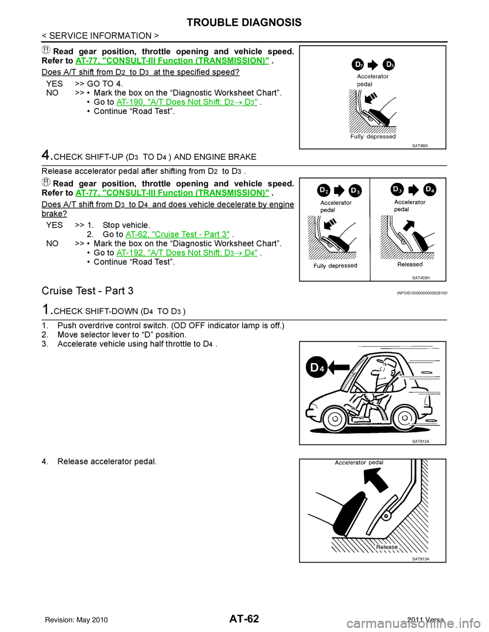
1.CHECK SHIFT-DOWN (D4 TO D3 )
1. Push overdrive control switch. (OD OFF indicator lamp is off.)
2. Move selector lever to “D” position.
3. Accelerate vehicle using half throttle to D
4 .
4. Release accelerator pedal.
SAT960I
SAT405H
SAT812A
SAT813A
Revision: May 2010 2011 Versa
Page 98 of 3787
TROUBLE DIAGNOSISAT-81
< SERVICE INFORMATION >
DE
F
G H
I
J
K L
M A
B
AT
N
O P
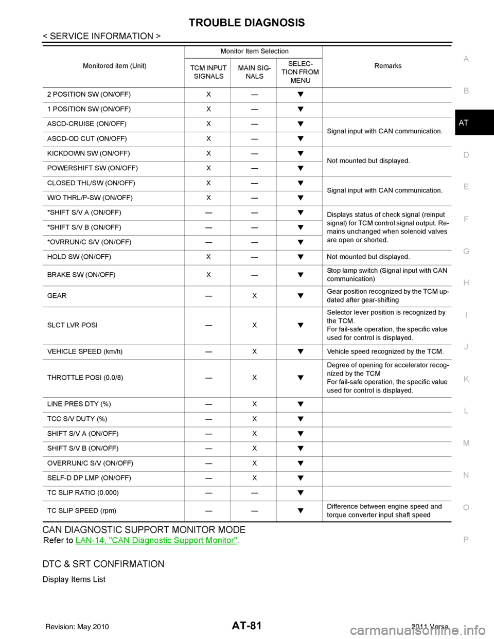
CAN DIAGNOSTIC SUPPORT MONITOR MODE
Refer to LAN-14, "CAN Diagnostic Support Monitor".
DTC & SRT CONFIRMATION
Display Items List
2 POSITION SW (ON/OFF) X—
1 POSITION SW (ON/OFF) X—
ASCD-CRUISE (ON/OFF) X—
Signal input with CAN communication.
ASCD-OD CUT (ON/OFF) X—
KICKDOWN SW (ON/OFF) X—
Not mounted but displayed.
POWERSHIFT SW (ON/OFF) X—
CLOSED THL/SW (ON/OFF) X—
Signal input with CAN communication.
W/O THRL/P-SW (ON/OFF) X—
*SHIFT S/V A (ON/OFF) ——
Displays status of check signal (reinput
signal) for TCM control signal output. Re-
mains unchanged when solenoid valves
are open or shorted.
*SHIFT S/V B (ON/OFF)
——
*OVRRUN/C S/V (ON/OFF) ——
HOLD SW (ON/OFF) X— Not mounted but displayed.
BRAKE SW (ON/OFF) X— Stop lamp switch (Signal input with CAN
communication)
GEAR —X Gear position recognized by the TCM up-
dated after gear-shifting
SLCT LVR POSI —X Selector lever position is recognized by
the TCM.
For fail-safe operation, the specific value
used for control is displayed.
VEHICLE SPEED (km/h) —X Vehicle speed reco gnized by the TCM.
THROTTLE POSI (0.0/8) —X Degree of opening for accelerator recog-
nized by the TCM
For fail-safe operation, the specific value
used for control is displayed.
LINE PRES DTY (%) —X
TCC S/V DUTY (%) —X
SHIFT S/V A (ON/OFF) —X
SHIFT S/V B (ON/OFF) —X
OVERRUN/C S/V (ON/OFF) —X
SELF-D DP LMP (ON/OFF) —X
TC SLIP RATIO (0.000) ——
TC SLIP SPEED (rpm) —— Difference between engine speed and
torque converter input shaft speed
Monitored item (Unit)
Monitor Item Selection
Remarks
TCM INPUT
SIGNALS MAIN SIG-
NALS SELEC-
TION FROM
MENU
Revision: May 2010 2011 Versa
Page 138 of 3787
P0734 4GR INCORRECT RATIOAT-121
< SERVICE INFORMATION >
DE
F
G H
I
J
K L
M A
B
AT
N
O P
- Valve, sleeve and plug slide along valve bore under their own weight.
- Valve, sleeve and plug are free from burrs, dents and scratches.
- Control valve springs are free from damage, deformation and fatigue.
- Hydraulic line is free from obstacles.
OK or NG
OK >> GO TO 6.
NG >> Repair control valve.
6.CHECK SHIFT-UP (D3 TO D4)
During AT-58, "
Cruise Test - Part 1".
Does A/T shift from D
3 to D4 at the specified speed?
YES >> GO TO 11.
NO >> Check control valve again. Repair or replace control valve assembly.
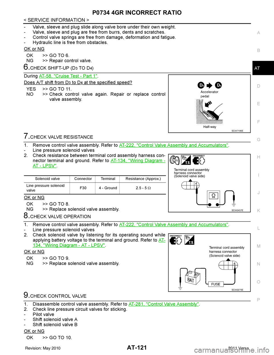
7.CHECK VALVE RESISTANCE
1. Remove control valve assembly. Refer to AT-222, "
Control Valve Assembly and Accumulators".
- Line pressure solenoid valves
2. Check resistance between terminal cord assembly harness con- nector terminal and ground. Refer to AT-134, "
Wiring Diagram -
AT - L P S V".
OK or NG
OK >> GO TO 8.
NG >> Replace solenoid valve assembly.
8.CHECK VALVE OPERATION
1. Remove control valve assembly. Refer to AT-222, "
Control Valve Assembly and Accumulators".
- Line pressure solenoid valves
2. Check solenoid valve by listening for its operating sound while applying battery voltage to the terminal and ground. Refer to AT-
134, "Wiring Diagram - AT - LPSV".
OK or NG
OK >> GO TO 9.
NG >> Replace solenoid valve assembly.
9.CHECK CONTROL VALVE
1. Disassemble control valve assembly. Refer to AT-281, "
Control Valve Assembly".
2. Check line pressure circuit valves for sticking.
- Pilot valve
- Shift solenoid valve A
- Shift solenoid valve B
OK or NG
OK >> GO TO 10.
SCIA7190E
Solenoid valve Connector Terminal Resistance (Approx.)
Line pressure solenoid
valve F30 4 - Ground 2.5 - 5
Ω
SCIA3457E
SCIA3275E
Revision: May 2010 2011 Versa