2011 NISSAN TIIDA steering wheel adjustment
[x] Cancel search: steering wheel adjustmentPage 3172 of 3787

MA-1
MAINTENANCE
C
DE
F
G H
I
J
K
M
SECTION MA
A
B
MA
N
O P
CONTENTS
MAINTENANCE
SERVICE INFORMATION .. ..........................3
PRECAUTIONS .............................................. .....3
Precaution for Supplemental Restraint System
(SRS) "AIR BAG" and "SEAT BELT PRE-TEN-
SIONER" ............................................................. ......
3
Precaution Necessary for Steering Wheel Rota-
tion After Battery Disconnect ............................... ......
3
PREPARATION ...................................................5
Special Service Tool ........................................... ......5
Commercial Service Tool ..........................................6
GENERAL MAINTENANCE ........................... .....7
Explanation of General Maintenance .................. ......7
General Maintenance ................................................7
PERIODIC MAINTENANCE ................................9
Introduction of Periodic Maintenance .................. ......9
Schedule 1 ................................................................9
Schedule 2 ..............................................................11
RECOMMENDED FLUIDS AND LUBRI-
CANTS ................................................................
14
Fluids and Lubricants .......................................... ....14
SAE Viscosity Number ............................................15
Anti-freeze Coolant Mixture Ratio ...........................15
ENGINE MAINTENANCE (HR16DE) .................16
DRIVE BELT .......................................................... ....16
DRIVE BELT : Checking .........................................16
DRIVE BELT : Tension Adjustment ........................16
ENGINE COOLANT ............................................... ....17
ENGINE COOLANT : Inspection .............................17
ENGINE COOLANT : Changing Engine Coolant ....17
FUEL LINES .......................................................... ....19
FUEL LINES : Checking Fuel Line ..........................19
AIR CLEANER FILTER ......................................... ....19
AIR CLEANER FILTER : Removal and Installation
....
20
ENGINE OIL ........................................................... ....20
ENGINE OIL : Inspection .........................................20
ENGINE OIL : Draining ............................................22
ENGINE OIL : Refilling ............................................22
OIL FILTER ............................................................ ....23
OIL FILTER : Removal and Installation ...................23
SPARK PLUG (HR16DE) ...................................... ....23
SPARK PLUG (HR16DE) : Exploded View .............24
SPARK PLUG (HR16DE) : Removal and Installa-
tion ....................................................................... ....
24
EVAP VAPOR LINES ............................................ ....25
EVAP VAPOR LINES : Checking EVAP Vapor
Line ..........................................................................
25
ENGINE MAINTENANCE (MR18DE) ...............26
DRIVE BELT .......................................................... ....26
DRIVE BELT : Component ......................................26
DRIVE BELT : Checking Drive Belts .......................26
DRIVE BELT : Tension Adjustment .........................26
ENGINE COOLANT ............................................... ....26
ENGINE COOLANT : Inspection .............................26
ENGINE COOLANT : Changing Engine Coolant ....27
FUEL LINES ........................................................... ....29
FUEL LINES : Checking Fuel Line ..........................29
AIR CLEANER FILTER ......................................... ....29
AIR CLEANER FILTER : Component ......................29
AIR CLEANER FILTER : Changing Air Cleaner
Filter .........................................................................
30
ENGINE OIL ........................................................... ....30
ENGINE OIL : Inspection .........................................30
ENGINE OIL : Changing Engine Oil ........................32
OIL FILTER ............................................................ ....33
Revision: May 2010 2011 Versa
Page 3317 of 3787

MTC-1
AIR CONDITIONER
C
DE
F
G H
I
K L
M
SECTION MTC
A
B
MTC
N
O P
CONTENTS
MANUAL AIR CONDITIONER
SERVICE INFORMATION .. ..........................3
PRECAUTIONS .............................................. .....3
Precaution for Supplemental Restraint System
(SRS) "AIR BAG" and "SEAT BELT PRE-TEN-
SIONER" ............................................................. ......
3
Precaution Necessary for Steering Wheel Rota-
tion After Battery Disconnect ............................... ......
3
Precaution for Procedure without Cowl Top Cover ......4
Precaution for Working with HFC-134a (R-134a) ......4
General Refrigerant Precaution ................................4
Oil Precaution ............................................................5
Precaution for Refrigerant Connection ......................5
Precaution for Service of Compressor ................ ......8
Precaution for Service Equipment ....................... ......8
Precaution for Leak Detection Dye ...........................9
PREPARATION ..................................................11
HFC-134a (R-134a) Service Tool and Equipment ....11
Commercial Service Tool ........................................14
REFRIGERATION SYSTEM ..............................15
Refrigerant Cycle ................................................ ....15
Refrigerant System Protection ................................15
Component Part Location ................................... ....16
OIL ......................................................................17
Maintenance of Oil Quantity in Compressor ....... ....17
AIR CONDITIONER CONTROL .........................19
Control Operation ................................................ ....19
Discharge Air Flow ..................................................20
System Description .................................................20
TROUBLE DIAGNOSIS .....................................22
CONSULT-III Function (BCM) ............................. ....22
How to Perform Trouble Diagnosis for Quick and
Accurate Repair ......................................................
23
Component Parts and Harness Connector Loca-
tion ...................................................................... ....
23
Schematic ...............................................................26
Wiring Diagram - Heater - .......................................27
Wiring Diagram - A/C,M - .................................... ....28
Operational Check ...................................................31
Mode Door ...............................................................32
Air Mix Door .............................................................33
Intake Door ..............................................................34
Front Blower Motor Circuit .......................................34
Magnet Clutch Circuit (If Equipped) ..................... ....38
Insufficient Cooling ..................................................46
Insufficient Heating ..................................................53
Noise .......................................................................54
CONTROLLER ..................................................56
Removal and Installation .........................................56
Disassembly and Assembly .....................................57
THERMO CONTROL AMPLIFIER ....................58
Removal and Installation .........................................58
A/C UNIT ASSEMBLY ......................................59
Removal and Installation .........................................59
Disassembly and Assembly .....................................61
BLOWER MOTOR ............................................63
Removal and Installation .........................................63
INTAKE DOOR ..................................................64
Intake Door Cable Adjustment .................................64
AIR MIX DOOR .................................................65
Air Mix Door Cable Adjustment ...............................65
MODE DOOR ....................................................66
Mode Door Cable Adjustment .................................66
BLOWER FAN RESISTOR ...............................67
Removal and Installation .........................................67
HEATER CORE .................................................68
Removal and Installation .........................................68
DUCTS AND GRILLES .....................................69
Removal and Installation .........................................69
Revision: May 2010 2011 Versa
Page 3500 of 3787

PS-6
< SERVICE INFORMATION >
STEERING WHEEL
STEERING WHEEL
On-Vehicle Inspection and ServiceINFOID:0000000006416714
CHECKING CONDITION OF INSTALLATION
• Check installation conditions of steering gear assembly, front suspension assembly, axle and steering col-
umn assembly.
• Check if movement exists when steering wheel is mo ved up and down, to the left and right and to the axial
direction.
• Check steering gear assembly bolts and nuts for looseness. Refer to PS-15, "
Removal and Installation".
CHECKING STEERING WHEEL PLAY
• Turn steering wheel so that front wheels come to the straight-ahead position. Start engine and lightly turn
steering wheel to the left and right until front wheels start to move. Measure steering wheel movement on the
outer circumference.
• When the measurement value is outside the standard val ue, check backlash for each joint of steering col-
umn assembly and installation condition of steering gear assembly.
CHECKING NEUTRAL POSITION STEERING WHEEL
• Make sure that steering gear assembly, steering column assembly and steering wheel are installed in the correct position.
• Perform neutral position inspection after wheel alignment. Refer to PS-2, "
Precaution for Supplemental
Restraint System (SRS) "AIR BAG" and "SEAT BELT PRE-TENSIONER"".
• Set vehicle to the straight-ahead position and c onfirm steering wheel is in the neutral position.
• Loosen outer socket lock nut and turn inner socket to left and right equally to make fine adjustments if steer-
ing wheel is not in the neutral position.
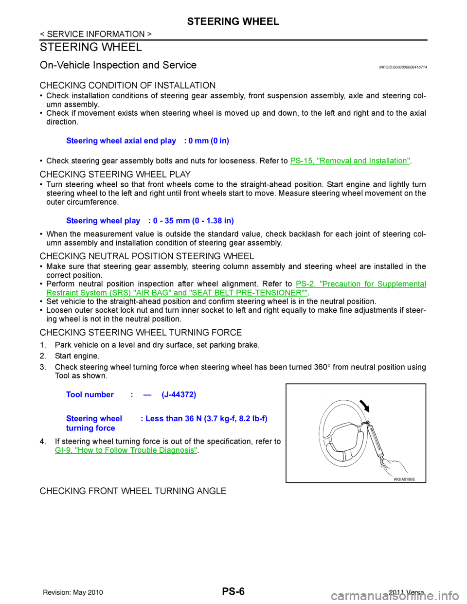
CHECKING STEERING WHEEL TURNING FORCE
1. Park vehicle on a level and dry surface, set parking brake.
2. Start engine.
3. Check steering wheel turning force when steering wheel has been turned 360 ° from neutral position using
Tool as shown.
4. If steering wheel turning force is out of the specification, refer to GI-9, "
How to Follow Trouble Diagnosis".
CHECKING FRONT WHEEL TURNING ANGLE
Steering wheel axial end play : 0 mm (0 in)
Steering wheel play : 0 - 35 mm (0 - 1.38 in)
Tool number : — (J-44372)
Steering wheel
turning force : Less than 36 N (3.7 kg-f, 8.2 lb-f)
WGIA0180E
Revision: May 2010
2011 Versa
Page 3512 of 3787

PS-18
< SERVICE INFORMATION >
POWER STEERING GEAR
3. Install inner socket to rack assembly. Torque to specified value while holding the flat portion of the racknext to the inner socket using a suitable tool.
4. Apply recommended grease to inner socket.
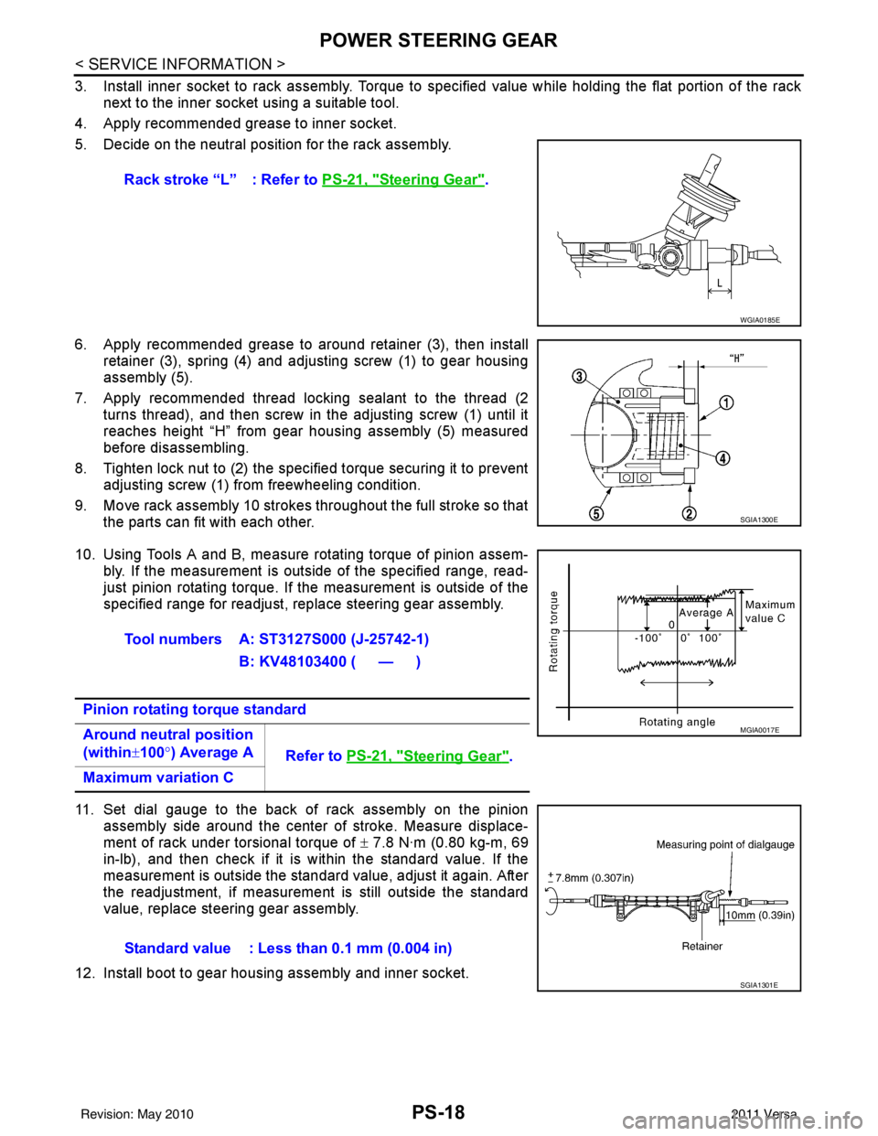
5. Decide on the neutral position for the rack assembly.
6. Apply recommended grease to around retainer (3), then install retainer (3), spring (4) and adjusting screw (1) to gear housing
assembly (5).
7. Apply recommended thread locking sealant to the thread (2 turns thread), and then screw in the adjusting screw (1) until it
reaches height “H” from gear housing assembly (5) measured
before disassembling.
8. Tighten lock nut to (2) the specified torque securing it to prevent adjusting screw (1) from freewheeling condition.
9. Move rack assembly 10 strokes throughout the full stroke so that the parts can fit with each other.
10. Using Tools A and B, measure rotating torque of pinion assem- bly. If the measurement is out side of the specified range, read-
just pinion rotating torque. If the measurement is outside of the
specified range for readjust, replace steering gear assembly.
11. Set dial gauge to the back of rack assembly on the pinion assembly side around the center of stroke. Measure displace-
ment of rack under torsional torque of ± 7.8 N·m (0.80 kg-m, 69
in-lb), and then check if it is within the standard value. If the
measurement is outside the standard value, adjust it again. After
the readjustment, if measurement is still outside the standard
value, replace steering gear assembly.
12. Install boot to gear housing assembly and inner socket. Rack stroke “L” : Refer to
PS-21, "
Steering Gear".
WGIA0185E
SGIA1300E
Tool numbers A: ST3127S000 (J-25742-1)
B: KV48103400 ( — )
Pinion rotating torque standard
Around neutral position
(within ±100° ) Average A
Refer to PS-21, "
Steering Gear".
Maximum variation C
MGIA0017E
Standard value : Less than 0.1 mm (0.004 in)
SGIA1301E
Revision: May 2010 2011 Versa
Page 3513 of 3787

POWER STEERING GEARPS-19
< SERVICE INFORMATION >
C
DE
F
H I
J
K L
M A
B
PS
N
O P
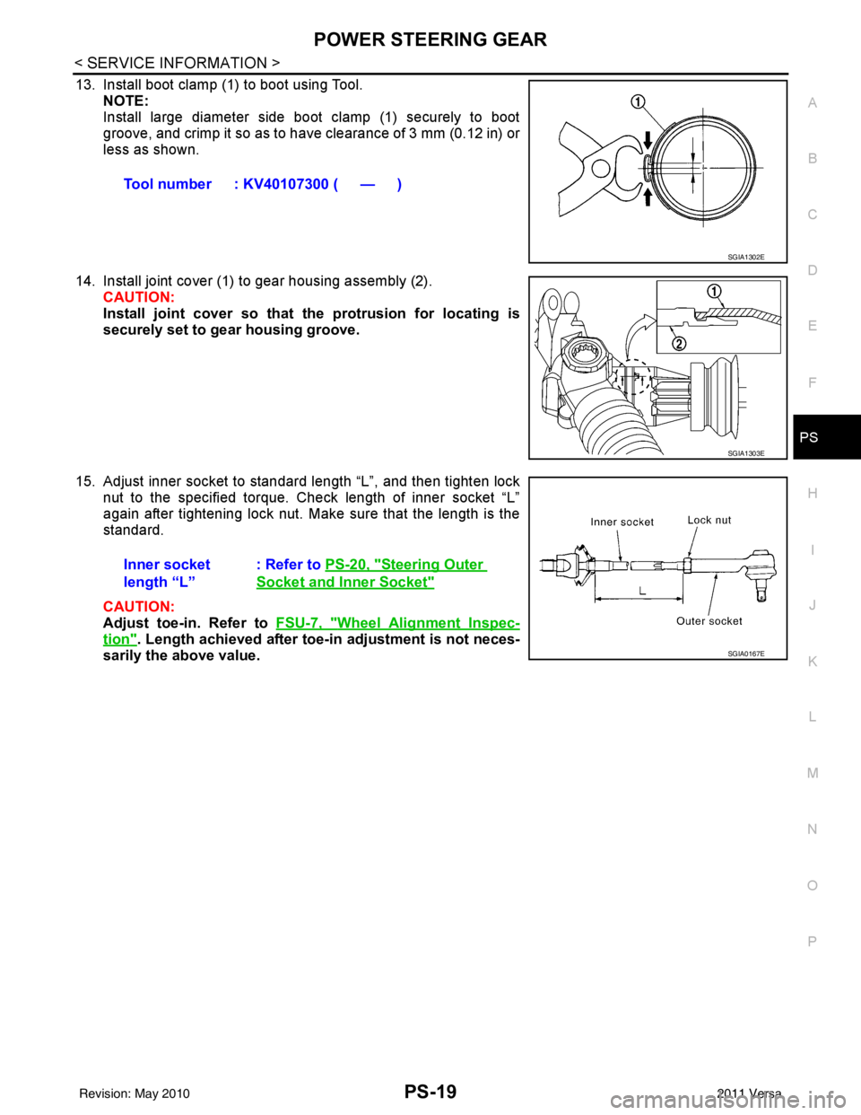
13. Install boot clamp (1) to boot using Tool. NOTE:
Install large diameter side boot clamp (1) securely to boot
groove, and crimp it so as to have clearance of 3 mm (0.12 in) or
less as shown.
14. Install joint cover (1) to gear housing assembly (2). CAUTION:
Install joint cover so that the protrusion for locating is
securely set to gear housing groove.
15. Adjust inner socket to standard length “L”, and then tighten lock nut to the specified torque. Check length of inner socket “L”
again after tightening lock nut. Make sure that the length is the
standard.
CAUTION:
Adjust toe-in. Refer to FSU-7, "
Wheel Alignment Inspec-
tion". Length achieved after toe-in adjustment is not neces-
sarily the above value. Tool number : KV40107300 ( — )
SGIA1302E
SGIA1303E
Inner socket
length “L”
: Refer to
PS-20, "Steering Outer
Socket and Inner Socket"
SGIA0167E
Revision: May 2010 2011 Versa
Page 3524 of 3787

RF-1
BODY
C
DE
F
G H
J
K L
M
SECTION RF
A
B
RF
N
O P
CONTENTS
ROOF
PRECAUTION ....... ........................................2
PRECAUTIONS .............................................. .....2
Precaution for Supplemental Restraint System
(SRS) "AIR BAG" and "SEAT BELT PRE-TEN-
SIONER" ............................................................. ......
2
Precaution Necessary for Steering Wheel Rota-
tion After Battery Disconnect ............................... ......
2
Precaution .................................................................3
PREPARATION ............................................4
PREPARATION .............................................. .....4
Commercial Service Tool .................................... ......4
SYMPTOM DIAGNOSIS ...............................5
SQUEAK AND RATTLE TROUBLE DIAG-
NOSES ........................ ........................................
5
Work Flow ........................................................... ......5
Generic Squeak and Rattle Troubleshooting ............7
Diagnostic Worksheet ...............................................9
FUNCTION DIAGNOSIS ..............................11
TROUBLE DIAGNOSIS ................................. ....11
Component Parts and Harness Connector Loca-
tion ....................................................................... ....
11
System Description ..................................................11
CAN Communication System Description ...............13
Wiring Diagram - SROOF - ......................................14
Terminal and Reference Value for BCM ..................15
Terminal and Reference Value for Sunroof Motor
Assembly ............................................................. ....
16
Work Flow ................................................................16
CONSULT-III Function (BCM) .................................16
Work Support ....................................................... ....17
Active Test ...............................................................17
Data Monitor ............................................................17
Trouble Diagnosis Chart by Symptom .....................17
BCM Power Supply and Ground Circuit Inspection
....
17
Sunroof Switch System Inspection ..........................17
Sunroof Motor Assembly Power Supply and
Ground Circuit Inspection ........................................
19
Door Switch Check ..................................................20
ON-VEHICLE REPAIR .................................22
SUNROOF .........................................................22
Removal and Installation ..................................... ....22
Fitting Adjustment ....................................................27
Inspection ................................................................28
Revision: May 2010 2011 Versa
Page 3715 of 3787
![NISSAN TIIDA 2011 Service Repair Manual STC-28
< SYMPTOM DIAGNOSIS >[EPS]
UNBALANCE STEERING WHEEL TURNING FORCE AND RETURN BETWEEN
RIGHT AND LEFT
UNBALANCE STEERING WHEEL TU RNING FORCE AND RETURN BE-
TWEEN RIGHT AND LEFT
DescriptionINFOI NISSAN TIIDA 2011 Service Repair Manual STC-28
< SYMPTOM DIAGNOSIS >[EPS]
UNBALANCE STEERING WHEEL TURNING FORCE AND RETURN BETWEEN
RIGHT AND LEFT
UNBALANCE STEERING WHEEL TU RNING FORCE AND RETURN BE-
TWEEN RIGHT AND LEFT
DescriptionINFOI](/manual-img/5/57396/w960_57396-3714.png)
STC-28
< SYMPTOM DIAGNOSIS >[EPS]
UNBALANCE STEERING WHEEL TURNING FORCE AND RETURN BETWEEN
RIGHT AND LEFT
UNBALANCE STEERING WHEEL TU RNING FORCE AND RETURN BE-
TWEEN RIGHT AND LEFT
DescriptionINFOID:0000000005931265
Unbalance steering wheel turning force and return between right and left.
Diagnosis ProcedureINFOID:0000000005931266
1.CHECK THE ILLUMINATION OF THE EPS WARNING LAMP
Check that the EPS warning lamp turns ON when igni tion switch turns ON. Then, EPS warning lamp turns
OFF after the engine is started.
Is the inspection result normal?
YES >> GO TO 2.
NO >> Refer to STC-26, "
Diagnosis Procedure".
2.CHECK WHEEL ALIGNMENT
1. Check the wheel alignment. Refer to FSU-7, "
On-Vehicle Inspection and Service".
2. Perform EPS control unit self-diagnosis.
Is the inspection result normal?
YES >> GO TO 3.
NO >> Adjustment of wheel alignment.
3.CHECK EPS CONTROL UNIT SIGNAL
With CONSULT-III
1. Start the engine. CAUTION:
Stop the vehicle.
2. Turn steering wheel from full left stop to full right stop.
3. Select “TORQUE SENSOR” of “DATA MONITOR” for EPS control unit.
Is the inspection result normal?
YES >> GO TO 5.
NO >> GO TO 4.
4.CHECK EPS MOTOR
Perform the trouble diagnosis of EPS motor. Refer to STC-13, "
Diagnosis Procedure".
Is the inspection result normal?
YES >> GO TO 5.
NO >> Repair or replace the specific malfunctioning part.
5.CHECK STEERING WHEEL TURNING FORCE
Check the steering wheel turning force. Refer to PS-6, "
On-Vehicle Inspection and Service".
Is the inspection result normal?
YES >> Inspection End.
NO >> Check the steering wheel turning force for mechanical malfunction. Refer to PS-6, "
On-Vehicle
Inspection and Service".
Monitor item ConditionDisplay value
TORQUE SENSOR Steering wheel: Not steer-
ing (There is no steering
force)
Approx. 0 Nm
Steering wheel: Right turn Positive value (Nm)
Steering wheel: Left turn Negative value (Nm)
Revision: May 2010 2011 Versa
Page 3719 of 3787

WT-1
SUSPENSION
C
DF
G H
I
J
K L
M
SECTION WT
A
B
WT
N
O PCONTENTS
ROAD WHEELS & TIRES
SERVICE INFORMATION .. ..........................2
PRECAUTIONS .............................................. .....2
Precaution for Supplemental Restraint System
(SRS) "AIR BAG" and "SEAT BELT PRE-TEN-
SIONER" ............................................................. ......
2
Precaution Necessary for Steering Wheel Rota-
tion After Battery Disconnect ............................... ......
2
PREPARATION ...................................................4
Special Service Tool ........................................... ......4
Commercial Service Tool ..........................................4
NOISE, VIBRATION AND HARSHNESS
(NVH) TROUBLESHOOTING .............................
5
NVH Troubleshooting Chart ................................ ......5
ROAD WHEEL ....................................................6
Inspection ............................................................ ......6
ROAD WHEEL TIRE ASSEMBLY ......................7
Adjustment .......................................................... ......7
TIRE PRESSURE MONITORING SYSTEM ........9
System Component ............................................. ......9
System Description ...................................................9
CAN COMMUNICATION ....................................11
System Description ............................................. ....11
TROUBLE DIAGNOSES ....................................12
Wiring Diagram- T/WARN - .....................................12
Terminal and Reference Value for BCM .................12
ID Registration Procedure .......................................13
Transmitter Wake Up Operation .............................14
CONSULT-III Function (BCM) .................................14
How to Perform Trouble Diagnosis for Quick and
Accurate Repair ................................................... ....
15
Preliminary Check ...................................................16
Self-Diagnosis (With CONSULT-III) ........................16
Self-Diagnosis (Without CONSULT-III) ...................17
TROUBLE DIAGNOSIS FOR SELF-DIAG-
NOSTIC ITEMS .................................................
20
Data from Transmitter Not Being Received .............20
Transmitter Malfunction ...........................................20
Transmitter Pressure Malfunction ............................21
Vehicle Speed Signal .......................................... ....21
Vehicle Ignition Signal .............................................22
TROUBLE DIAGNOSIS FOR SYMPTOMS ......23
Low Tire Pressure Warning Lamp Does Not Come
On When Ignition Switch Is Turned On ...................
23
Low Tire Pressure Warning Lamp Stays On When
Ignition Switch Is Turned On ............................... ....
23
Low Tire Pressure Warning Lamp Flashes When
Ignition Switch Is Turned On ...................................
24
Hazard Warning Lamps Flash When Ignition
Switch Is Turned On ................................................
25
ID Registration Cannot Be Completed ....................25
REMOVAL AND INSTALLATION .....................26
Transmitter (Pressure Sens or) ................................26
SERVICE DATA AND SPECIFICATIONS
(SDS) .................................................................
28
Road Wheel ......................................................... ....28
Tire ..........................................................................28
Revision: May 2010 2011 Versa