2011 NISSAN TIIDA steering wheel adjustment
[x] Cancel search: steering wheel adjustmentPage 2392 of 3787
EM-2
IGNITION COIL, SPARK PLUG AND ROCK-
ER COVER .........................................................
46
Exploded View ........................................................46
Removal and Installation ........................................46
TIMING CHAIN ............................................... ...49
Exploded View ..................................................... ...49
Removal and Installation ........................................49
Inspection ...............................................................57
CAMSHAFT .......................................................59
Exploded View ..................................................... ...59
Removal and Installation ........................................59
Inspection ...............................................................65
OIL SEAL ...........................................................70
VALVE OIL SEAL .................................................. ...70
VALVE OIL SEAL : Removal and Installation .........70
FRONT OIL SEAL .................................................. ...70
FRONT OIL SEAL : Removal and Installation ........71
REAR OIL SEAL .................................................... ...71
REAR OIL SEAL : Removal and Installation ..........71
CYLINDER HEAD ........................................... ...73
Removal and Installation ..................................... ...73
Disassembly and Assembly ....................................76
REMOVAL AND INSTALLATION ...............82
ENGINE ASSEMBLY ...................................... ...82
Exploded View ..................................................... ...82
Removal and Installation ........................................82
Inspection ...............................................................85
DISASSEMBLY AND ASSEMBLY .............87
ENGINE STAND SETTING ............................. ...87
Setting ................................................................. ...87
ENGINE UNIT ....................................................88
Disassembly ........................................................ ...88
Assembly ................................................................88
CYLINDER BLOCK ...........................................89
Exploded View ..................................................... ...89
Disassembly and Assembly ....................................90
Inspection ...............................................................97
HOW TO SELECT PISTON AND BEARING ...106
Description ........................................................... ..106
Connecting Rod Bearing .......................................106
Main Bearing .........................................................108
SERVICE DATA AND SPECIFICATIONS
(SDS) ........................................................ ..
111
SERVICE DATA AND SPECIFICATIONS
(SDS) ............................................................... .
111
General Specification .......................................... ..111
Drive Belts ............................................................ .111
Spark Plug ............................................................112
Exhaust Manifold ..................................................112
Camshaft ...............................................................112
Cylinder Head .......................................................114
Cylinder Block .......................................................116
Connecting Rod Bearing .......................................119
Main Bearing .........................................................120
MR18DE
SERVICE INFORMATION .. .......................
122
PRECAUTIONS .............................................. ..122
Precaution for Supplemental Restraint System
(SRS) "AIR BAG" and "SEAT BELT PRE-TEN-
SIONER" .............................................................. .
122
Precaution Necessary for Steering Wheel Rota-
tion After Battery Disconnect ................................
122
Precaution for Procedure without Cowl Top Cover .123
Precaution for Drain Coolant .................................123
Precaution for Disconnecting Fuel Piping ............ .123
Precaution for Removal and Disassembly ............123
Precaution for Inspection, Repair and Replace-
ment ......................................................................
123
Precaution for Assembly and Installation ............. .123
Parts Requiring Angular Tightening ......................124
Precaution for Liquid Gasket .................................124
PREPARATION ................................................126
Special Service Tool ............................................ .126
Commercial Service Tool ......................................128
NOISE, VIBRATION AND HARSHNESS
(NVH) TROUBLESHOOTING ...........................
130
NVH Troubleshooting - Engine Noise .................. .130
Use the Chart Below to Help You Find the Cause
of the Symptom .................................................... .
131
DRIVE BELTS ..................................................132
Component .......................................................... .132
Checking Drive Belts .............................................132
Tension Adjustment ..............................................132
Removal and Installation .......................................132
Component .......................................................... .133
Removal and Installation of Drive Belt Auto Ten-
sioner ....................................................................
133
AIR CLEANER AND AIR DUCT .......................135
Component .......................................................... .135
Removal and Installation .......................................135
Changing Air Cleaner Filter ...................................136
INTAKE MANIFOLD ....................................... ..137
Component .......................................................... .137
Removal and Installation .......................................137
Inspection ............................................................. .139
EXHAUST MANIFOLD .....................................141
Component .......................................................... .141
Removal and Installation .......................................141
Revision: May 2010 2011 Versa
Page 2473 of 3787
![NISSAN TIIDA 2011 Service Repair Manual ENGINE ASSEMBLYEM-83
< REMOVAL AND INSTALLATION > [HR16DE]
C
D
E
F
G H
I
J
K L
M A
EM
NP
O
• If items or work required are not covered by the engine section, follow the procedures in the applica-
bl NISSAN TIIDA 2011 Service Repair Manual ENGINE ASSEMBLYEM-83
< REMOVAL AND INSTALLATION > [HR16DE]
C
D
E
F
G H
I
J
K L
M A
EM
NP
O
• If items or work required are not covered by the engine section, follow the procedures in the applica-
bl](/manual-img/5/57396/w960_57396-2472.png)
ENGINE ASSEMBLYEM-83
< REMOVAL AND INSTALLATION > [HR16DE]
C
D
E
F
G H
I
J
K L
M A
EM
NP
O
• If items or work required are not covered by the engine section, follow the procedures in the applica-
ble sections.
• Always use the support poin t specified for lifting.
• Use either 2-pole lift type or separate type lift as best you can. If board-on type is used for unavoid-
able reasons, support at the rear axle jacking point with a transmission jack or similar tool before
starting work, in preparation for the backward shif t of center of gravity.
• For supporting points fo r lifting and jacking point at rear axle, refer to GI-38, "
Garage Jack and
Safety Stand and 2-Pole Lift".
REMOVAL
Outline
Remove the engine and the transaxle assembly from t he vehicle downward. Separate the engine and the tran-
saxle.
Preparation
1. Remove the hood assembly. Refer to BL-14, "Removal and Installation".
2. Remove the cowl top cover and cowl top extension assembly. Refer to EI-24, "
Removal and Installation".
3. Release fuel pressure. Refer to EC-499, "
Inspection".
4. Drain engine coolant from radiator. Refer to CO-11, "
Changing Engine Coolant".
CAUTION:
• Perform this step when the engine is cold.
• Never spill engine coolant on drive belt.
5. Remove the following parts. • Engine under cover. Refer to EI-15, "
Removal and Installation".
• Front road wheels and tires. Refer to WT-7, "
Adjustment".
• Front fender protector (RH and LH). Refer to EI-26, "
Removal and Installation".
• Battery and battery tray. Refer to SC-7, "
Removal and Installation".
• Drive belt. Refer to EM-14, "
Removal and Installation".
• Air duct and air cleaner case assembly. Refer to EM-25, "
Exploded View".
• Radiator hose (upper and lower). Refer to CO-16, "
Component".
• Disconnect cooling fan controller wiring harness.
• Remove coolant reservoir tank.
• Remove fan shroud and cooling fan assembly. Refer to CO-18, "
Component (Models with A/C)" or CO-
18, "Component (Models without A/C)".
Engine Room LH
1. Disconnect all connections of engine harness around the engine mounting insulator (LH), and then tem-
porarily secure the engine harness into the engine side.
CAUTION:
Protect connectors using a resin bag against foreign materials.
2. Remove ground cable at transaxle side.
3. Disconnect fuel feed hose at engine side. Refer to EM-33, "
Exploded View".
4. Disconnect EVAP purge hose and brake booster vacuum hose.
5. Disconnect heater hoses, and install plugs them to prevent engine coolant from draining. Refer to CO-16,
"Component".
6. Disconnect control linkage from transaxle. Refer to AT-213, "
A/T Shift Selector Removal and Installation"
(A/T), MT-14, "Exploded View" (M/T).
7. Disconnect the clutch tube at tr ansmission side (if equipped). Refer to CL-15, "
Removal and Installation".
Engine Room RH
1. Remove ground cable between front cover and vehicle.
2. Remove generator and generator br acket (A/C models). Refer to SC-25, "
Removal and Installation".
3. Remove A/C compressor with piping connected from t he engine. Temporarily secure it on the vehicle side
with a rope to avoid putting load on it (if equipped). Refer to MTC-78, "
Removal and Installation of Com-
pressor - HR16DE".
Vehicle Underbody
1. Remove front wheel sensor (LH and RH) for ABS from steering knuckle (if equipped). Refer to BRC-33,
"Removal and Installation" (ABS) or BRC-86, "Removal and Installation" (VDC/TCS/ABS).
Revision: May 2010 2011 Versa
Page 2648 of 3787
FAX-6
< SERVICE INFORMATION >
FRONT WHEEL HUB AND KNUCKLE
FRONT WHEEL HUB AND KNUCKLE
On-Vehicle Inspection and ServiceINFOID:0000000005931068
• Check the axle and suspension parts for excessive play, wear, or damage.
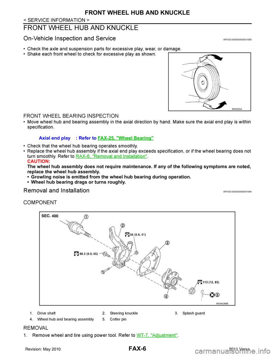
• Shake each front wheel to check for excessive play as shown.
FRONT WHEEL BEARING INSPECTION
• Move wheel hub and bearing assembly in the axial direction by hand. Make sure the axial end play is within
specification.
• Check that the wheel hub bearing operates smoothly.
• Replace the wheel hub assembly if the axial end play exceeds specification, or if the wheel bearing does not turn smoothly. Refer to RAX-6, "
Removal and Installation".
CAUTION:
The wheel hub assembly does not requ ire maintenance. If any of the following symptoms are noted,
replace the wheel hub assembly.
• Growling noise is emitted from the wheel hub bearing during operation.
• Wheel hub bearing drags or turns roughly.
Removal and InstallationINFOID:0000000005931069
COMPONENT
REMOVAL
1. Remove wheel and tire using power tool. Refer to WT-7, "Adjustment".
SMA525A
Axial end play : Refer to FAX-25, "Wheel Bearing"
1. Drive shaft 2. Steering knuckle3. Splash guard
4. Wheel hub and bearing assembly 5. Cotter pin
WDIA0366E
Revision: May 2010 2011 Versa
Page 2651 of 3787
FRONT DRIVE SHAFTFAX-9
< SERVICE INFORMATION >
CEF
G H
I
J
K L
M A
B
FA X
N
O P
FRONT DRIVE SHAFT
On-Vehicle Inspection and ServiceINFOID:0000000005931070
• Check drive shaft mounting point and joint for looseness and other damage.
• Check boot for cracks and other damage.
Replace or repair components as necessary. Refer to FAX-9, "
Removal and Installation (Left Side)", FAX-10,
"Removal and Installation (Right Side)", FAX-13, "Disassembly and Assembly (Left Side)", or FAX-18, "Disas-
sembly and Assembly (Right Side)".
CAUTION:
Replace entire drive shaft assembly when noi se or vibration occur from drive shaft.
Removal and Installation (Left Side)INFOID:0000000005931071
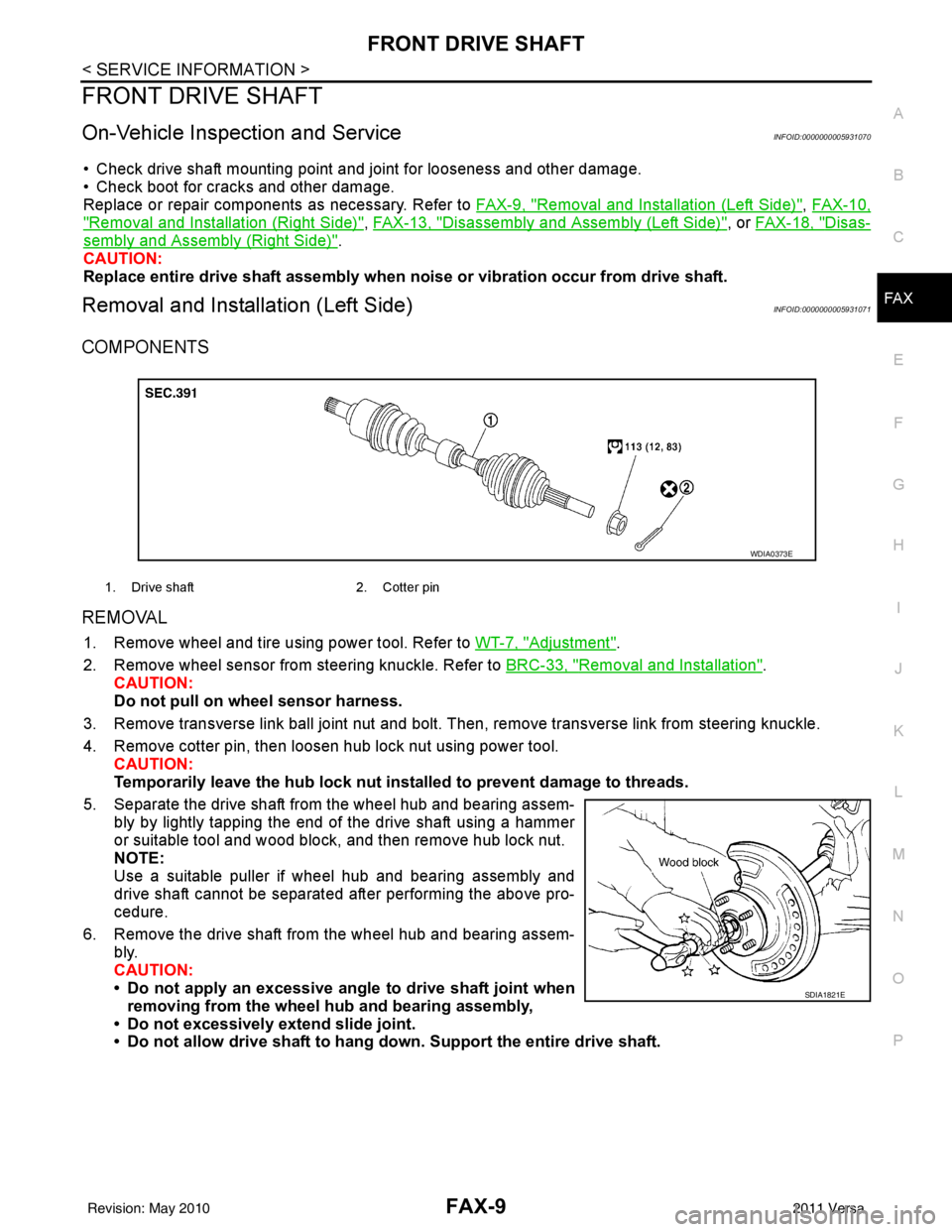
COMPONENTS
REMOVAL
1. Remove wheel and tire using power tool. Refer to WT-7, "Adjustment".
2. Remove wheel sensor from steering knuckle. Refer to BRC-33, "
Removal and Installation".
CAUTION:
Do not pull on wheel sensor harness.
3. Remove transverse link ball joint nut and bolt. Then, remove transverse link from steering knuckle.
4. Remove cotter pin, then loosen hub lock nut using power tool. CAUTION:
Temporarily leave the hub lock nut inst alled to prevent damage to threads.
5. Separate the drive shaft from the wheel hub and bearing assem- bly by lightly tapping the end of the drive shaft using a hammer
or suitable tool and wood block, and then remove hub lock nut.
NOTE:
Use a suitable puller if wheel hub and bearing assembly and
drive shaft cannot be separated after performing the above pro-
cedure.
6. Remove the drive shaft from the wheel hub and bearing assem- bly.
CAUTION:
• Do not apply an excessive angle to drive shaft joint when
removing from the wheel hub and bearing assembly,
• Do not excessively extend slide joint.
• Do not allow drive shaft to hang do wn. Support the entire drive shaft.
1. Drive shaft 2. Cotter pin
WDIA0373E
SDIA1821E
Revision: May 2010 2011 Versa
Page 2653 of 3787
FRONT DRIVE SHAFTFAX-11
< SERVICE INFORMATION >
CEF
G H
I
J
K L
M A
B
FA X
N
O P
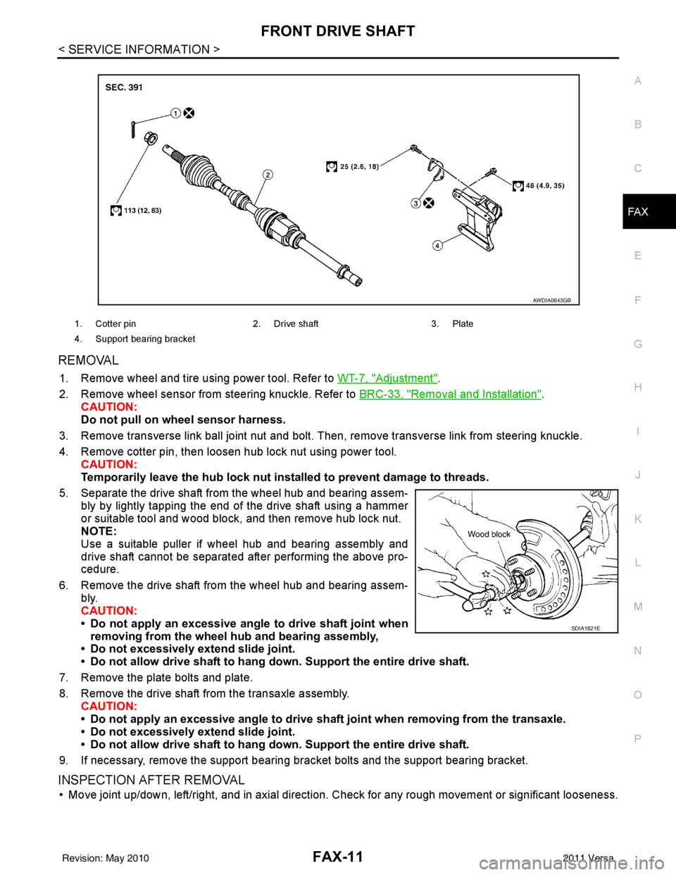
REMOVAL
1. Remove wheel and tire using power tool. Refer to WT-7, "Adjustment".
2. Remove wheel sensor from steering knuckle. Refer to BRC-33, "
Removal and Installation".
CAUTION:
Do not pull on wheel sensor harness.
3. Remove transverse link ball joint nut and bolt. Then, remove transverse link from steering knuckle.
4. Remove cotter pin, then loosen hub lock nut using power tool. CAUTION:
Temporarily leave the hub lock nut inst alled to prevent damage to threads.
5. Separate the drive shaft from the wheel hub and bearing assem- bly by lightly tapping the end of the drive shaft using a hammer
or suitable tool and wood block, and then remove hub lock nut.
NOTE:
Use a suitable puller if wheel hub and bearing assembly and
drive shaft cannot be separated after performing the above pro-
cedure.
6. Remove the drive shaft from the wheel hub and bearing assem- bly.
CAUTION:
• Do not apply an excessive angle to drive shaft joint when
removing from the wheel hub and bearing assembly,
• Do not excessively extend slide joint.
• Do not allow drive shaft to hang do wn. Support the entire drive shaft.
7. Remove the plate bolts and plate.
8. Remove the drive shaft from the transaxle assembly. CAUTION:
• Do not apply an excessive angle to drive shaf t joint when removing from the transaxle.
• Do not excessively extend slide joint.
• Do not allow drive shaft to hang do wn. Support the entire drive shaft.
9. If necessary, remove the support bearing bracket bolts and the support bearing bracket.
INSPECTION AFTER REMOVAL
• Move joint up/down, left/right, and in axial direction. Check for any rough movement or significant looseness.
1. Cotter pin 2. Drive shaft 3. Plate
4. Support bearing bracket
AWDIA0643GB
SDIA1821E
Revision: May 2010 2011 Versa
Page 2692 of 3787
FRONT SUSPENSION ASSEMBLYFSU-7
< SERVICE INFORMATION >
C
DF
G H
I
J
K L
M A
B
FSU
N
O P
FRONT SUSPENSION ASSEMBLY
On-Vehicle Inspection and ServiceINFOID:0000000005930898
Make sure the mounting conditions (looseness, back lash) of each component and component conditions
(wear, damage) are normal.
INSPECTION OF LOWER BALL JOINT END PLAY
1. Set front wheels in a straight-ahead position. Do not depress brake pedal.
2. Place an iron bar or similar tool between transverse link and steering knuckle.
3. Measure axial end play by prying it up and down.
CAUTION:
Be careful not to damage ball joint boot. Do not damage the installation position by applying
excessive force.
STRUT INSPECTION
Check for oil leakage, damage and replace as necessary.
Wheel Alignment InspectionINFOID:0000000005930899
PRELIMINARY INSPECTION
WARNING:
Always adjust the alignment with the vehicle on a flat surface.
NOTE:
If alignment is out of specification, inspect and replace any damaged or worn rear suspension parts before
making any adjustments.
1. Check and adjust the wheel alignment with the vehicle under unladen conditions. “Unladen conditions”
means that the fuel, coolant, and lubricant are full; and that the spare tire, jack, hand tools and mats are in
their designated positions.
2. Check the tires for incorrect air pressure and excessive wear.
3. Check the wheels for run out and damage. Refer to WT-6, "
Inspection".
4. Check the wheel bearing axial end play. Refer to FAX-6, "
On-Vehicle Inspection and Service".
5. Check the shock absorbers for leaks or damage.
6. Check each mounting point of the suspension components for any excessive looseness or damage.
7. Check each link, arm, and the suspension member for any damage.
8. Check the vehicle height. Refer to FSU-19, "
Wheelarch Height (Unladen*)".
GENERAL INFORMATION AND RECOMMENDATIONS
1. A Four-Wheel Thrust Alignment should be performed.
• This type of alignment is re commended for any NISSAN vehicle.
• The four-wheel “thrust” process helps ensure that the vehicle is properly aligned and the steering wheel
is centered.
• The alignment machine itself should be ca pable of accepting any NISSAN vehicle.
• The alignment machine should be checked to ensure that it is level.
2. Make sure the alignment machine is properly calibrated. • Your alignment machine should be regularly calibrated in order to give correct information.
• Check with the manufacturer of your specific a lignment machine for their recommended Service/Cali-
bration Schedule.
THE ALIGNMENT PROCESS
IMPORTANT: Use only the alignment specifications listed in this Service Manual. Refer to FSU-17, "Wheel
Alignment (Unladen*)".
1. When displaying the alignment settings, many alignm ent machines use “indicators”: (Green/red, plus or
minus, Go/No Go). Do NOT use these indicators.
• The alignment specifications programmed into your alignment machine that operate these indicators may not be correct.Axial end play : 0 mm (0 in)
Revision: May 2010
2011 Versa
Page 2700 of 3787
TRANSVERSE LINKFSU-15
< SERVICE INFORMATION >
C
DF
G H
I
J
K L
M A
B
FSU
N
O P
TRANSVERSE LINK
Removal and InstallationINFOID:0000000006414956
REMOVAL
1. Remove wheel and tire. Refer to WT-7, "Adjustment".
2. Remove transverse link ball joint nut and bolt. Then, remove transverse link from steering knuckle.
3. Remove transverse link nuts and bolts, then remove transverse link from front suspension member.
NOTE:
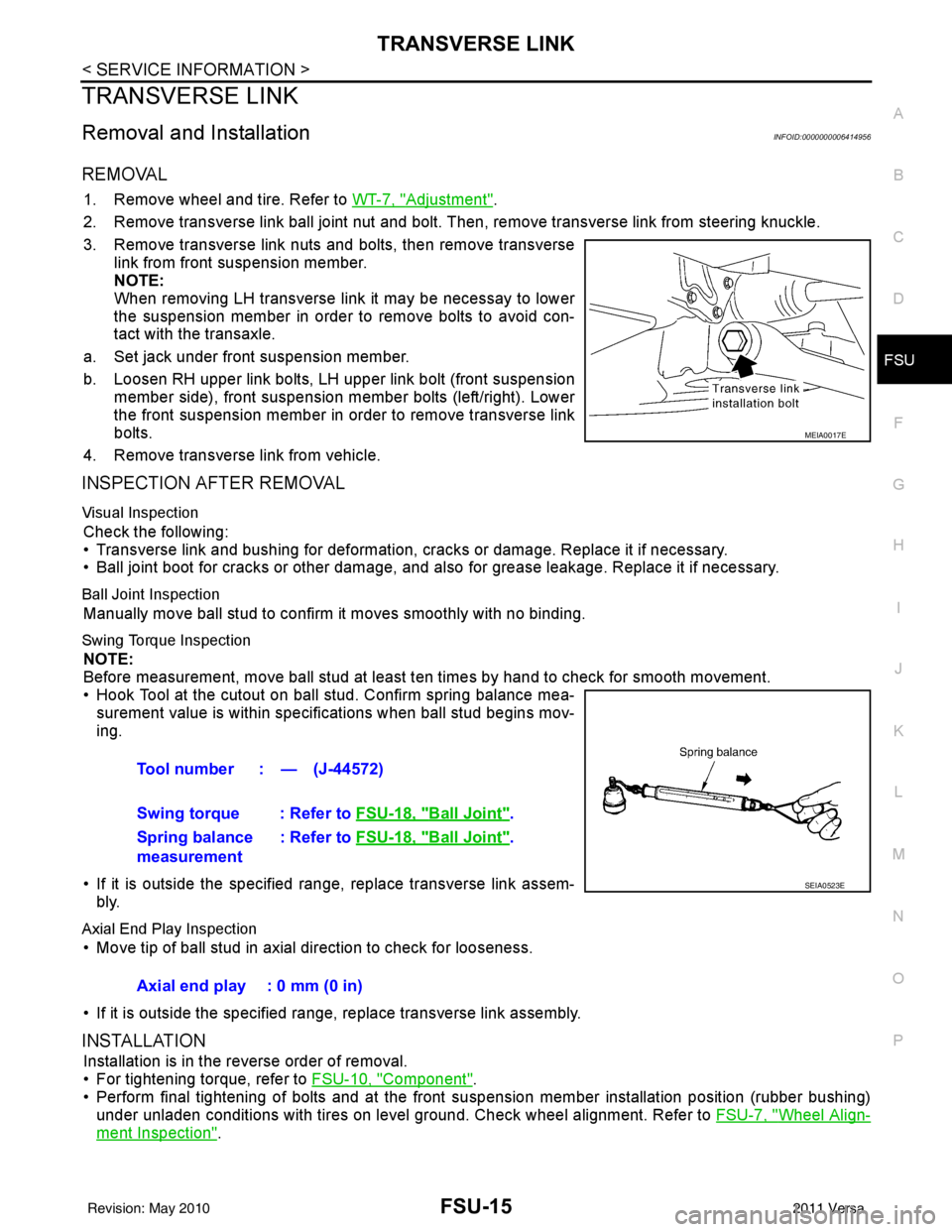
When removing LH transverse link it may be necessay to lower
the suspension member in order to remove bolts to avoid con-
tact with the transaxle.
a. Set jack under front suspension member.
b. Loosen RH upper link bolts, LH upper link bolt (front suspension member side), front suspension member bolts (left/right). Lower
the front suspension member in order to remove transverse link
bolts.
4. Remove transverse link from vehicle.
INSPECTION AFTER REMOVAL
Visual Inspection
Check the following:
• Transverse link and bushing for deformation, cracks or damage. Replace it if necessary.
• Ball joint boot for cracks or other damage, and also for grease leakage. Replace it if necessary.
Ball Joint Inspection
Manually move ball stud to confirm it moves smoothly with no binding.
Swing Torque Inspection
NOTE:
Before measurement, move ball stud at least ten times by hand to check for smooth movement.
• Hook Tool at the cutout on ball stud. Confirm spring balance mea- surement value is within specifications when ball stud begins mov-
ing.
• If it is outside the specified range, replace transverse link assem- bly.
Axial End Play Inspection
• Move tip of ball stud in axial direction to check for looseness.
• If it is outside the specified range, replace transverse link assembly.
INSTALLATION
Installation is in the reverse order of removal.
• For tightening torque, refer to FSU-10, "
Component".
• Perform final tightening of bolts and at the front suspension member installation position (rubber bushing)
under unladen conditions with tires on level ground. Check wheel alignment. Refer to FSU-7, "
Wheel Align-
ment Inspection".
MEIA0017E
Tool number : — (J-44572)
Swing torque : Refer to FSU-18, "
Ball Joint".
Spring balance
measurement : Refer to
FSU-18, "
Ball Joint".
SEIA0523E
Axial end play : 0 mm (0 in)
Revision: May 2010 2011 Versa
Page 3033 of 3787
LT-1
ELECTRICAL
C
DE
F
G H
I
J
L
M
SECTION LT
A
B
LT
N
O P
CONTENTS
LIGHTING SYSTEM
SERVICE INFORMATION .. ..........................3
PRECAUTIONS .............................................. .....3
Precaution for Supplemental Restraint System
(SRS) "AIR BAG" and "SEAT BELT PRE-TEN-
SIONER" ............................................................. ......
3
Precaution Necessary for Steering Wheel Rota-
tion After Battery Disconnect ............................... ......
3
HEADLAMP (FOR USA) .....................................5
Component Parts and Harness Connector Loca-
tion ...................................................................... ......
5
System Description ...................................................5
CAN COMMUNICATION SYSTEM DESCRIP-
TION .................................................................... ......
6
Schematic .................................................................7
Wiring Diagram .........................................................8
Terminal and Reference Value for BCM .................11
Terminal and Reference Value for IPDM E/R .........11
How to Perform Trouble Diagnosis .........................12
Preliminary Check ...................................................12
CONSULT-III Function (BCM) .................................12
CONSULT-III Function (IPDM E/R) .........................13
Headlamp High Beam Does Not Illuminate (Both
Sides) .................................................................. ....
15
Headlamp High Beam Does Not Illuminate (One
Side) .................................................................... ....
17
High Beam Indicator Lamp Does Not Illuminate .....18
Headlamp Low Beam Does Not Illuminate (Both
Sides) .................................................................. ....
19
Headlamp Low Beam Does Not Illuminate (One
Side) .................................................................... ....
21
Headlamps Do Not Turn OFF .................................22
Aiming Adjustment ..................................................23
Bulb Replacement ...................................................24
Removal and Installation .........................................25
Disassembly and Assembly ................................ ....25
HEADLAMP (FOR CANADA) - DAYTIME
LIGHT SYSTEM - ........................................... ....
27
Component Parts and Harness Connector Loca-
tion ....................................................................... ....
27
System Description ..................................................27
CAN Communication System Description ...............29
Schematic ................................................................30
Wiring Diagram - DTRL - .........................................31
Terminal and Reference Value for BCM ..................34
Terminal and Reference Value for IPDM E/R ...... ....34
How to Perform Trouble Diagnosis ..........................35
Preliminary Check ...................................................35
CONSULT-III Function (BCM) .................................35
CONSULT-III Function (IPDM E/R) ..................... ....35
Daytime Light Control Does Not Operate Properly
(High Beam Headlamps Operate Properly) .............
35
Aiming Adjustment ...................................................37
Bulb Replacement ...................................................38
Removal and Installation .........................................39
Disassembly and Assembly .....................................39
FRONT FOG LAMP ..........................................41
Component Parts and Harness Connector Loca-
tion ...........................................................................
41
System Description ..................................................41
CAN Communication System Description ...............42
Wiring Diagram - F/FOG - .......................................43
Terminal and Reference Value for BCM ..................44
Terminal and Reference Value for IPDM E/R ...... ....44
How to Proceed with Trouble Diagnosis ..................45
Preliminary Check ............................................... ....45
CONSULT-III Function (BCM) .................................45
CONSULT-III Function (IPDM E/R) ..................... ....45
Front Fog lamps Do Not Illuminate (Both Sides) .....45
Front Fog Lamp Does Not Illuminate (One Side) ....47
Aiming Adjustment ...................................................48
Bulb Replacement ...................................................49
Removal and Installation .........................................49
TURN SIGNAL AND HAZARD WARNING
LAMPS ..............................................................
50
Component Parts and Harness Connector Loca-
tion ...........................................................................
50
Revision: May 2010 2011 Versa