2011 NISSAN TIIDA Adjust the belt tension
[x] Cancel search: Adjust the belt tensionPage 3362 of 3787
MTC-46
< SERVICE INFORMATION >
TROUBLE DIAGNOSIS
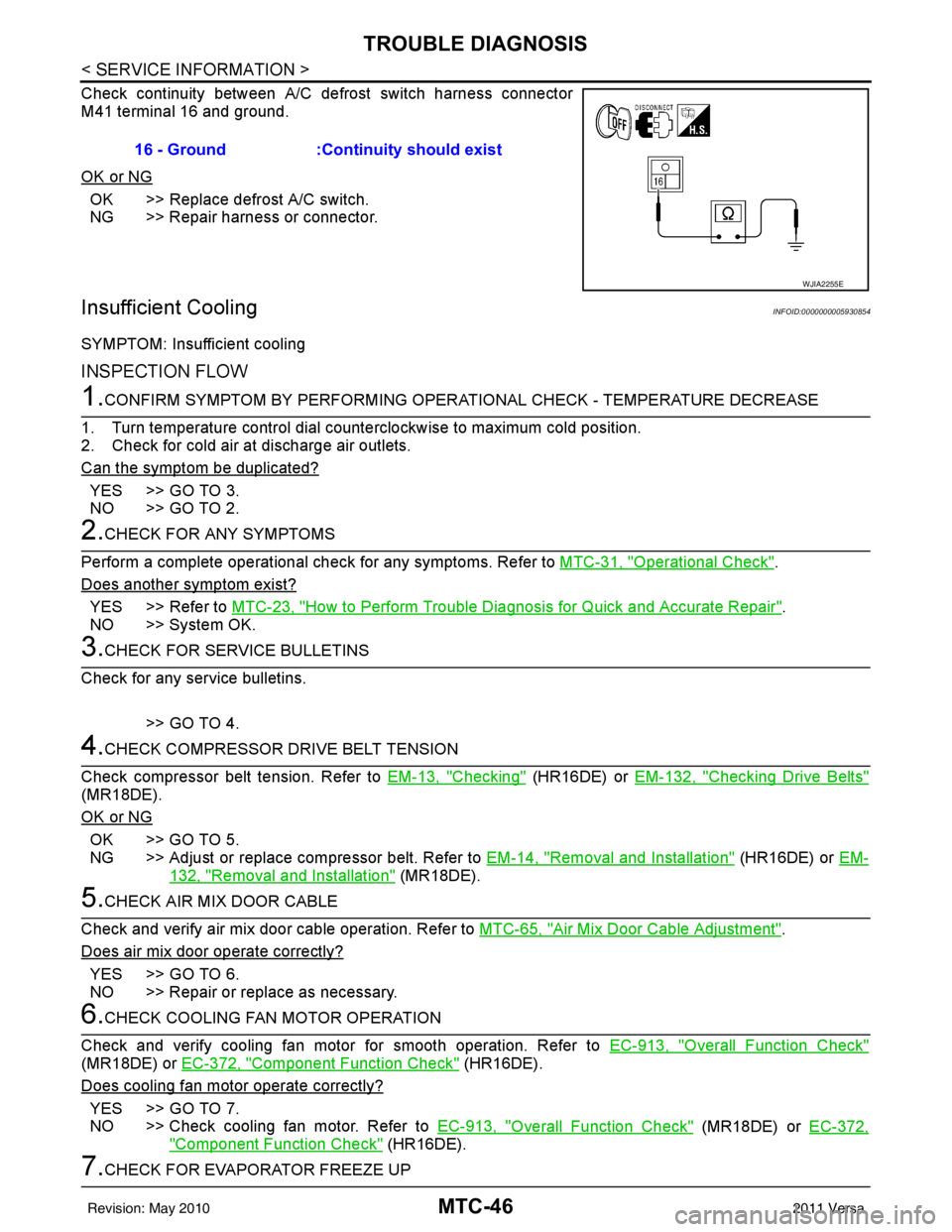
Check continuity between A/C defrost switch harness connector
M41 terminal 16 and ground.
OK or NG
OK >> Replace defrost A/C switch.
NG >> Repair harness or connector.
Insufficient CoolingINFOID:0000000005930854
SYMPTOM: Insufficient cooling
INSPECTION FLOW
1.CONFIRM SYMPTOM BY PERFORMING OPERATIONAL CHECK - TEMPERATURE DECREASE
1. Turn temperature control dial counterclockwise to maximum cold position.
2. Check for cold air at discharge air outlets.
Can the symptom be duplicated?
YES >> GO TO 3.
NO >> GO TO 2.
2.CHECK FOR ANY SYMPTOMS
Perform a complete operational check for any symptoms. Refer to MTC-31, "
Operational Check".
Does another symptom exist?
YES >> Refer to MTC-23, "How to Perform Trouble Diagnosis for Quick and Accurate Repair".
NO >> System OK.
3.CHECK FOR SERVICE BULLETINS
Check for any service bulletins.
>> GO TO 4.
4.CHECK COMPRESSOR DRIVE BELT TENSION
Check compressor belt tension. Refer to EM-13, "
Checking" (HR16DE) or EM-132, "Checking Drive Belts"
(MR18DE).
OK or NG
OK >> GO TO 5.
NG >> Adjust or replace compressor belt. Refer to EM-14, "
Removal and Installation" (HR16DE) or EM-
132, "Removal and Installation" (MR18DE).
5.CHECK AIR MIX DOOR CABLE
Check and verify air mix door cable operation. Refer to MTC-65, "
Air Mix Door Cable Adjustment".
Does air mix door operate correctly?
YES >> GO TO 6.
NO >> Repair or replace as necessary.
6.CHECK COOLING FAN MOTOR OPERATION
Check and verify cooling fan motor for smooth operation. Refer to EC-913, "
Overall Function Check"
(MR18DE) or EC-372, "Component Function Check" (HR16DE).
Does cooling fan motor operate correctly?
YES >> GO TO 7.
NO >> Check cooling fan motor. Refer to EC-913, "
Overall Function Check" (MR18DE) or EC-372,
"Component Function Check" (HR16DE).
7.CHECK FOR EVAPORATOR FREEZE UP16 - Ground :Continuity should exist
WJIA2255E
Revision: May 2010
2011 Versa
Page 3500 of 3787
PS-6
< SERVICE INFORMATION >
STEERING WHEEL
STEERING WHEEL
On-Vehicle Inspection and ServiceINFOID:0000000006416714
CHECKING CONDITION OF INSTALLATION
• Check installation conditions of steering gear assembly, front suspension assembly, axle and steering col-
umn assembly.
• Check if movement exists when steering wheel is mo ved up and down, to the left and right and to the axial
direction.
• Check steering gear assembly bolts and nuts for looseness. Refer to PS-15, "
Removal and Installation".
CHECKING STEERING WHEEL PLAY
• Turn steering wheel so that front wheels come to the straight-ahead position. Start engine and lightly turn
steering wheel to the left and right until front wheels start to move. Measure steering wheel movement on the
outer circumference.
• When the measurement value is outside the standard val ue, check backlash for each joint of steering col-
umn assembly and installation condition of steering gear assembly.
CHECKING NEUTRAL POSITION STEERING WHEEL
• Make sure that steering gear assembly, steering column assembly and steering wheel are installed in the correct position.
• Perform neutral position inspection after wheel alignment. Refer to PS-2, "
Precaution for Supplemental
Restraint System (SRS) "AIR BAG" and "SEAT BELT PRE-TENSIONER"".
• Set vehicle to the straight-ahead position and c onfirm steering wheel is in the neutral position.
• Loosen outer socket lock nut and turn inner socket to left and right equally to make fine adjustments if steer-
ing wheel is not in the neutral position.
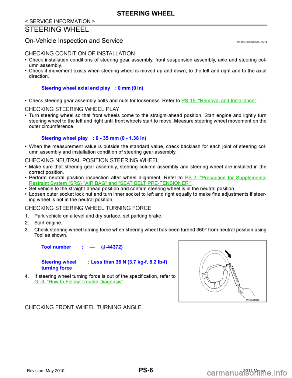
CHECKING STEERING WHEEL TURNING FORCE
1. Park vehicle on a level and dry surface, set parking brake.
2. Start engine.
3. Check steering wheel turning force when steering wheel has been turned 360 ° from neutral position using
Tool as shown.
4. If steering wheel turning force is out of the specification, refer to GI-9, "
How to Follow Trouble Diagnosis".
CHECKING FRONT WHEEL TURNING ANGLE
Steering wheel axial end play : 0 mm (0 in)
Steering wheel play : 0 - 35 mm (0 - 1.38 in)
Tool number : — (J-44372)
Steering wheel
turning force : Less than 36 N (3.7 kg-f, 8.2 lb-f)
WGIA0180E
Revision: May 2010
2011 Versa
Page 3570 of 3787
SB-4
< ON-VEHICLE REPAIR >
SEAT BELTS
ON-VEHICLE REPAIR
SEAT BELTS
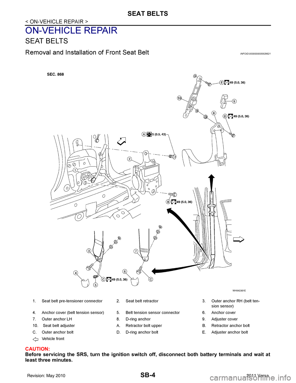
Removal and Installation of Front Seat BeltINFOID:0000000005929621
CAUTION:
Before servicing the SRS, turn th e ignition switch off, disconnect both battery terminals and wait at
least three minutes.
1. Seat belt pre-tensioner connector 2. Seat belt retractor 3. Outer anchor RH (belt ten-
sion sensor)
4. Anchor cover (belt tension sensor) 5. Belt tension sensor connector 6. Anchor cover
7. Outer anchor LH 8. D-ring anchor 9. Adjuster cover
10. Seat belt adjuster A. Retractor bolt upper B. Retractor anchor bolt
C. Outer anchor bolt D. D-ring anchor bolt E. Adjuster anchor bolt
Vehicle front
WHIA0361E
Revision: May 2010 2011 Versa
Page 3571 of 3787
SEAT BELTSSB-5
< ON-VEHICLE REPAIR >
C
DE
F
G
I
J
K L
M A
B
SB
N
O P
REMOVAL OF SEAT BELT RETRACTOR
1. Disconnect both the negative and positive battery te rminals, then wait at least three minutes.
2. Remove the adjuster cover and D-ring anchor bolt.
3. Remove both the center pillar upper and lower garnish. Refer to EI-41
.
WARNING:
Do not reuse center pillar upper garnish if removed.
4. Pull the floor trim away from center pillar.
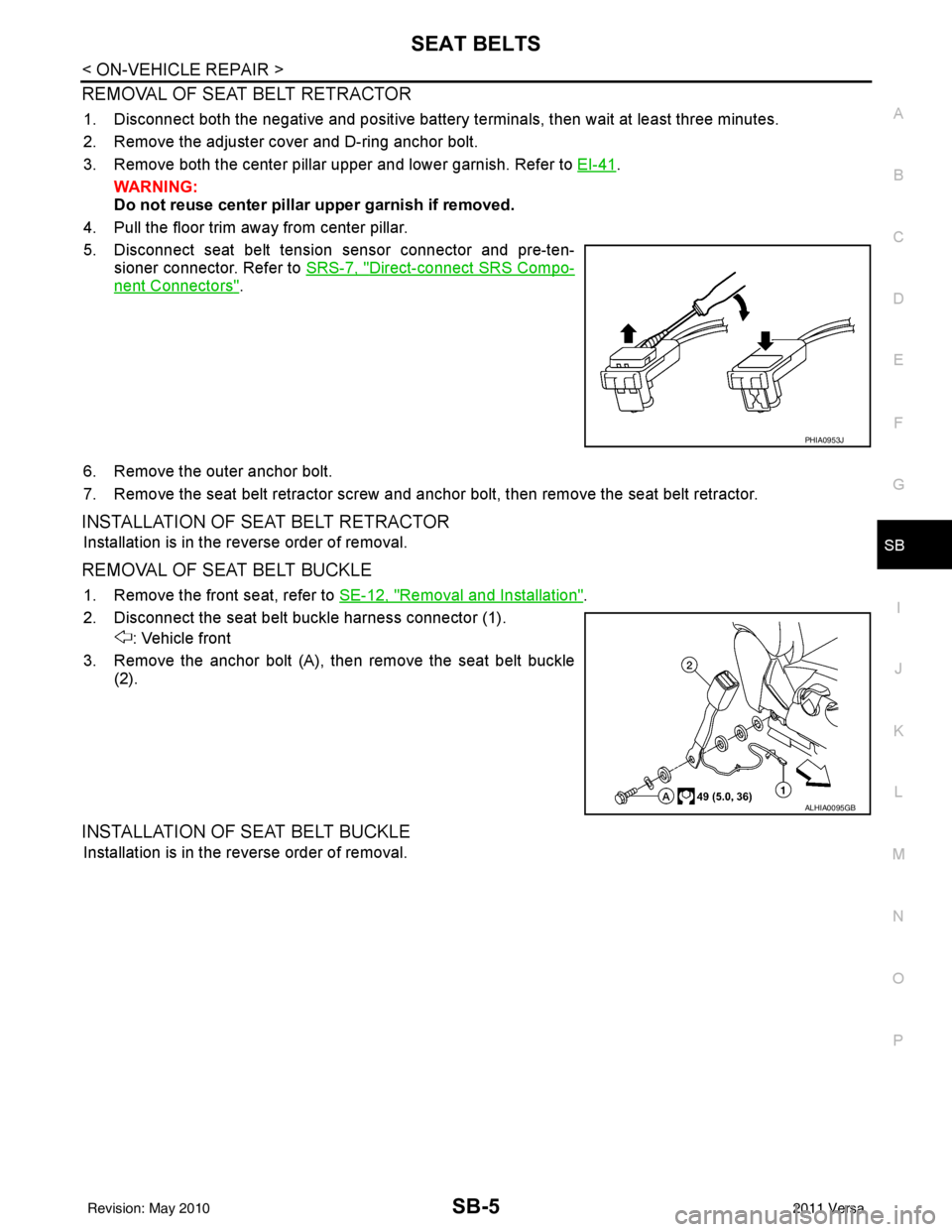
5. Disconnect seat belt tension sensor connector and pre-ten- sioner connector. Refer to SRS-7, "
Direct-connect SRS Compo-
nent Connectors".
6. Remove the outer anchor bolt.
7. Remove the seat belt retractor screw and anchor bolt, then remove the seat belt retractor.
INSTALLATION OF SEAT BELT RETRACTOR
Installation is in the reverse order of removal.
REMOVAL OF SEAT BELT BUCKLE
1. Remove the front seat, refer to SE-12, "Removal and Installation".
2. Disconnect the seat belt buckle harness connector (1). : Vehicle front
3. Remove the anchor bolt (A), then remove the seat belt buckle (2).
INSTALLATION OF SEAT BELT BUCKLE
Installation is in the reverse order of removal.
PHIA0953J
ALHIA0095GB
Revision: May 2010 2011 Versa
Page 3575 of 3787
SEAT BELTSSB-9
< ON-VEHICLE REPAIR >
C
DE
F
G
I
J
K L
M A
B
SB
N
O P
• The seat belt was in use at the time of a collision (except for minor collisions and the belts, retractors and buckles show no damage and continue to operate properly).
• The seat belt was damaged in an accident. (i.e. torn webbing, bent retractor or guide, etc.)
• The seat belt attaching point was damaged in an accident. Inspect the seat belt attaching area for damage
or distortion and repair as necessary before installing a new seat belt assembly.
• Anchor bolts are deformed or worn out.
• The seat belt pre-tensioner should be replaced even if the seat belts are not in use during a frontal collision
in which the air bags are deployed.
PRELIMINARY CHECKS
1. Check the seat belt warning lamp/chime for proper operation as follows:
a. Switch ignition ON. The seat belt warning lamp should illuminate. Also, the seat belt warning chime should sound for about seven seconds.
b. Fasten driver's seat belt. The seat belt warning lamp should go out and the chime (if sounding) should stop.
2. If the air bag warning lamp is blinking, conduct self-diagnosis using CONSULT-III, and air bag warning
lamp. Refer to SRS-19, "
SRS Operation Check".
3. Check that the seat belt retractor, seat belt anchor and buckle bolts are securely attached.
4. Check the shoulder seat belt guide and shoulder belt height adjuster for front seats. Make sure guide
swivels freely and that webbing lays flat and does not bind in guide. Make sure height adjuster operates
properly and holds securely.
5. Check retractor operation:
a. Fully extend the seat belt webbing and check for twists, tears or other damage.
b. Allow the seat belt to retract. Make sure that webbing returns smoothly and completely into the retractor. If the seat belt does not return smoothly, wipe the inside of the loops with a clean paper cloth. Dirt build-up
in the loops of the upper anchors can caus e the seat belts to retract slowly.
c. Fasten the seat belt. Check the seat belt returns sm oothly and completely to the retractor. If the webbing
does not return smoothly, the cause may be an accu mulation of dust or dirt. Use the “SEAT BELT TAPE
SET” and perform the following steps.
Inspect the front seat belt though-anchor
1. Pull the seat belt out to a length of 500 mm (19.69 in) or more.
2. Use a clip or other device to attach t he seat belt at the center pillar webbing opening.
3. Pass a thin wire though the D-ring anchor webbing opening. Hold both end\
s of the wire and pull taut while moving it up and down several times along the webbing opening surface to remove matter stuck
there.
4. Any dirt that cannot be removed with the wire can be removed by cleaning the opening with a clean
cloth.
5. Apply tape at the point where the webbing contacts the though-anchor webbing opening.
NOTE:
Apply the tape so that there is no looseness or wrinkling.
6. Remove the clip attaching the seat bel t and check that the webbing returns smoothly.
6. Repeat steps above as necessary to check the other seat belts.
SEAT BELT RETRACTOR ON-VEHICLE CHECK
Emergency Locking Retractors (ELR) and Automatic Locking Retractors (ALR)
NOTE:
All seat belt retractors are of the Emergency Locki ng Retractors (ELR) type. In an emergency (sudden stop)
the retractor will lock and prevent the webbing from extending any further. All 3-point type seat belt retractors
except the driver's seat belt also have an Automati c Locking Retractors (ALR) mode. The ALR mode (also
called child restraint mode) is used when installing child seats. The ALR mode is activated when the seat belt
is fully extended. When the webbing is then retracted part ially, the ALR mode automatically locks the seat belt
in a specific position so the webbing cannot be extended any further. To cancel the ALR mode, allow the seat
belt to fully wind back into the retractor.
Check the seat belt retractors using the following test(s ) to determine if a retractor assembly is operating prop-
erly.
ELR Function Stationary Check
Revision: May 2010 2011 Versa
Page 3683 of 3787
COLLISION DIAGNOSISSRS-49
< ON-VEHICLE REPAIR >
C
DE
F
G
I
J
K L
M A
B
SRS
N
O P
FOR FRONTAL COLLISION: When SRS is not activated in a collision
CAUTION:
Due to varying models and option levels, not all parts listed in the chart below apply to all vehicles.
WORK PROCEDURE
1. Before performing any of the following steps, ensur e that all vehicle body and structural repairs have been
completed.
2. Check the SRS components using the table below: Replace any SRS components showing visible signs of damage. (dents, cracks and deformation, etc.)
3. Perform self-diagnosis using CONSULT-III or air bag warning lamp. Refer to SRS-18, "
Self-Diagnosis
Function (Without CONSULT-III)" for details.
Ensure entire SRS operates properly.
4. After the work is completed, perform self-diagnosis to check that no malfunction is detected. Refer to
SRS-19, "
SRS Operation Check".
SRS INSPECTION (FOR FRONTAL COLLISION)
Harness and connectors 1. Check connectors for poor connection, damage, and terminals for deformities.
2. Check harness for binding, chafing, cuts, or deformities.
3. If no damage is found, reinstall the harness and connectors.
4. If damaged—REPLACE the damaged harness. Do not attempt to repair, splice or modify any SRS harness.
Instrument panel assembly If the passenger front air bag has deployed: REPLACE the instrument panel assembly. (integrated type)
Part
Inspection
Part Inspection
Driver air bag module If the driver air bag has NOT been activated:
1. Remove driver air bag module. Check harness cover and connectors for damage, terminals for deformities, and harness for binding.
2. Install driver air bag module into the steering wheel to check fit and alignment with the wheel.
3. If no damage is found, reinstall with new fasteners.
4. If damaged—REPLACE. Install driver air bag modules with new fasteners.
Front passenger air bag module
(if equipped) If the front passenger air bag has NOT been activated:
1. Remove front passenger air bag module. Check harness cover and connectors for damage,
terminals for deformities, and harness for binding.
2. Install front passenger air bag module into the instrument panel to check fit with the instrument panel.
3. If no damage is found, reinstall with new fasteners.
4. If damaged—REPLACE. Install front passenger air bag modules with new fasteners.
Crash zone sensor If the front air bags or seat belt pre-tensioners have NOT been activated:
1. Remove the crash zone sensor. Check harness connectors for damage, terminals for defor- mities, and harness for binding.
2. Check for visible signs of damage (dents, cracks, deformation) of the crash zone sensor and bracket.
3. Install the crash zone sensor to check fit.
4. If no damage is found, reinstall with new fasteners.
5. If damaged—REPLACE the crash zone sensor and bracket with new fasteners.
Seat belt pre-tensioner assem-
blies
(All applicable locations: buckle,
retractor, lap outer) If the pre-tensioners have NOT been activated:
1. Remove seat belt pre-tensioners.
Check harness cover and connectors for damage, terminals for deformities, and harness for
binding.
2. Check belts for damage and anchors for loose mounting.
3. Check retractor for smooth operation.
4. Check seat belt adjuster for damage.
5. Check for deformities of the center pillar inner.
6. If the center pillar inner has no damage, REPLACE the seat belt pre-tensioner assembly.
7. If no damage is found, reinstall seat belt pre-tensioner assembly.
8. If damaged—REPLACE. Install the seat belt pre-tensioners with new fasteners.
Revision: May 2010 2011 Versa
Page 3686 of 3787

SRS-52
< ON-VEHICLE REPAIR >
COLLISION DIAGNOSIS
PartInspection
Side curtain air bag module LH If the side curtain air bag LH has NOT deployed: 1. Check for visible signs of damage (dents, tears, deformation) of the center pillar on the colli-sion side.
2. If damaged—Remove the side curtain air bag module LH.
3. Check for visible signs of damaged (tears etc.) of the side curtain air bag module LH.
4. Check harness and connectors for damage, and terminals for deformities.
5. If no damage is found, reinstall the side curtain air bag module LH with new fasteners.
6. If damaged—REPLACE the side curtain air bag module LH with new fasteners.
Side curtain air bag module RH If the side curtain air bag RH has NOT deployed: 1. Check for visible signs of damage (dents, tears, deformation) of the center pillar on the colli-
sion side.
2. If damaged—Remove the side curtain air bag module RH.
3. Check for visible signs of damaged (tears etc.) of the side curtain air bag module RH.
4. Check harness and connectors for damage, and terminals for deformities.
5. If no damage is found, reinstall the side curtain air bag module RH with new fasteners.
6. If damaged—REPLACE the side curtain air bag module RH with new fasteners.
Front side air bag module LH If the front LH side air bag has NOT deployed: 1. Check for visible signs of damage (dents, tears, deformation) of the seat back on the collision side.
2. Check harness and connectors for damage, and terminals for deformities.
3. If damaged—REPLACE the front seatback assembly LH.
Front side air bag module RH If the front side air bag RH has NOT deployed: 1. Check for visible signs of damage (dents, tears, deformation) of the seat back on the collision side.
2. Check harness and connectors for damage, and terminals for deformities.
3. If damaged—REPLACE the front seatback assembly RH.
Side air bag (satellite) sensor (LH
or RH) If none of the SRS components have been activated:
1. Remove the side air bag (satellite) sensor (LH or RH) on the collision side. Check harness
connectors for damage, te rminals for deformities, and harness for binding.
2. Check for visible signs of damage (dents, cracks, deformation) of the side air bag (satellite) sensor (LH or RH).
3. Install the side air bag (satellite) sensor (LH or RH) to check fit.
4. If no damage is found, reinstall the side sir bag (satellite) sensor (LH or RH) with new fasten- ers.
5. If damaged—REPLACE the side air bag (satellite) sensor (LH or RH) with new fasteners.
Diagnosis sensor unit If none of the SRS components have been activated:
1. Check case and bracket for dents, cracks or deformities.
2. Check connectors for damage, and terminals for deformities.
3. If no damage is found, reinstall the diagnosis sensor unit with new fasteners.
4. If damaged—REPLACE the diagnosis sensor unit with new fasteners.
Seat belt pre-tensioner assem-
blies
(All applicable locations: buckle,
retractor, lap outer) If the pre-tensioners have NOT been activated:
1. Remove seat belt pre-tensioners.
Check harness cover and connectors for damage, terminals for deformities, and harness for
binding.
2. Check belts for damage and anchors for loose mounting.
3. Check retractor for smooth operation.
4. Check seat belt adjuster for damage.
5. Check for deformities of the center pillar inner.
6. If the center pillar inner has no damage, REPLACE the seat belt pre-tensioner assembly.
7. If no damage is found, reinstall seat belt pre-tensioner assembly.
8. If damaged—REPLACE. Install the seat belt pre-tensioners with new fasteners.
Seat (with front side air bag) If the front LH or front RH side air bag modules have NOT deployed: 1. Visually check the seat on the collision side.
2. Remove the seat on the collision side and check the following for damage and deformities.
- Harness, connectors and terminals
- Frame and recliner (for front and rear seat), and also adjuster and slides (for front seat)
3. If no damage is found, reinstall the seat.
4. If damaged—REPLACE the damaged seat parts using new fasteners. If the front seat back is damaged, the front seat back assembly must be replaced.
Revision: May 2010 2011 Versa