Page 783 of 3787

BODY REPAIRBL-273
< SERVICE INFORMATION >
C
DE
F
G H
J
K L
M A
B
BL
N
O P
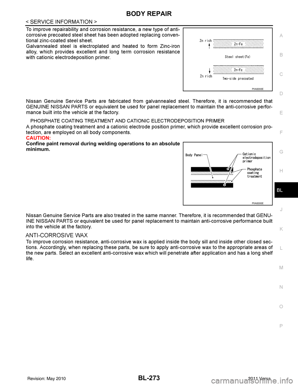
To improve repairability and corrosion resistance, a new type of anti-
corrosive precoated steel sheet has been adopted replacing conven-
tional zinc-coated steel sheet.
Galvannealed steel is electroplated and heated to form Zinc-iron
alloy, which provides excellent and long term corrosion resistance
with cationic electrodeposition primer.
Nissan Genuine Service Parts are fabricated from galvannealed steel. Therefore, it is recommended that
GENUINE NISSAN PARTS or equivalent be used for panel replacement to maintain the anti-corrosive perfor-
mance built into the vehicle at the factory.
PHOSPHATE COATING TREATMENT AND CA TIONIC ELECTRODEPOSITION PRIMER
A phosphate coating treatment and a cationic electrode posit ion primer, which provide excellent corrosion pro-
tection, are employed on all body components.
CAUTION:
Confine paint removal during weld ing operations to an absolute
minimum.
Nissan Genuine Service Parts are also treated in the same manner. Therefore, it is recommended that GENU-
INE NISSAN PARTS or equivalent be used for panel repl acement to maintain anti-corrosive performance built
into the vehicle at the factory.
ANTI-CORROSIVE WAX
To improve corrosion resistance, anti-corrosive wax is applied inside the body sill and inside other closed sec-
tions. Accordingly, when replacing these parts, be sure to apply anti-corrosive wax to the appropriate areas of
the new parts. Select an excellent anti-corrosive wax which will penetrate after application and has a long shelf
life.
PIIA0093E
PIIA0095E
Revision: May 2010 2011 Versa
Page 815 of 3787

BODY REPAIRBL-305
< SERVICE INFORMATION >
C
DE
F
G H
J
K L
M A
B
BL
N
O P
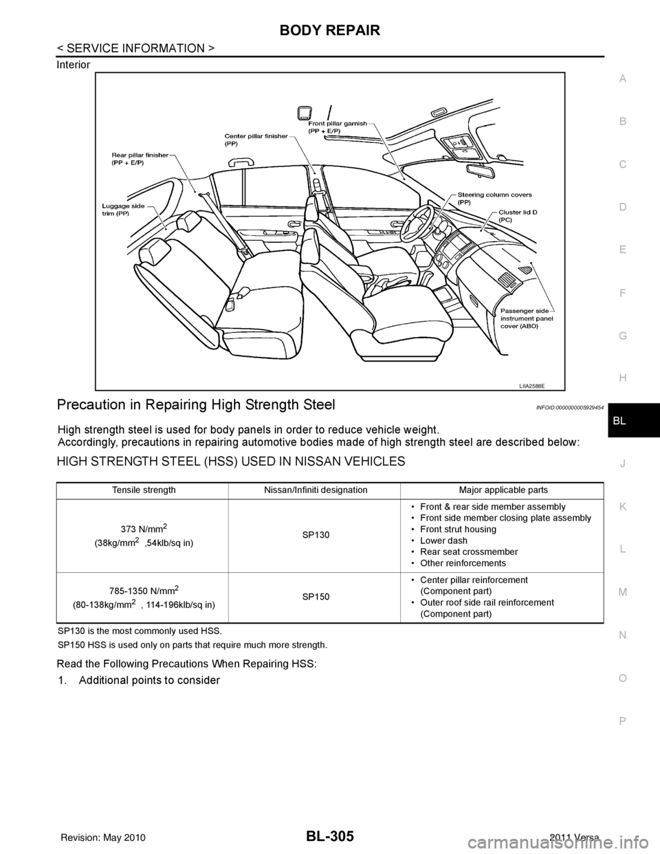
Interior
Precaution in Repairing High Strength SteelINFOID:0000000005929454
High strength steel is used for body panels in order to reduce vehicle weight.
Accordingly, precautions in repairing automotive bodies made of high strength steel are described below:
HIGH STRENGTH STEEL (HSS) USED IN NISSAN VEHICLES
SP130 is the most commonly used HSS.
SP150 HSS is used only on parts that require much more strength.
Read the Following Precautions When Repairing HSS:
1. Additional points to consider
LIIA2588E
Tensile strength
Nissan/Infiniti designation Major applicable parts
373 N/mm
2
(38kg/mm2 ,54klb/sq in) SP130• Front & rear side member assembly
• Front side member closing plate assembly
• Front strut housing
• Lower dash
• Rear seat crossmember
• Other reinforcements
785-1350 N/mm
2
(80-138kg/mm2 , 114-196klb/sq in) SP150• Center pillar reinforcement
(Component part)
• Outer roof side rail reinforcement (Component part)
Revision: May 2010 2011 Versa
Page 816 of 3787

BL-306
< SERVICE INFORMATION >
BODY REPAIR
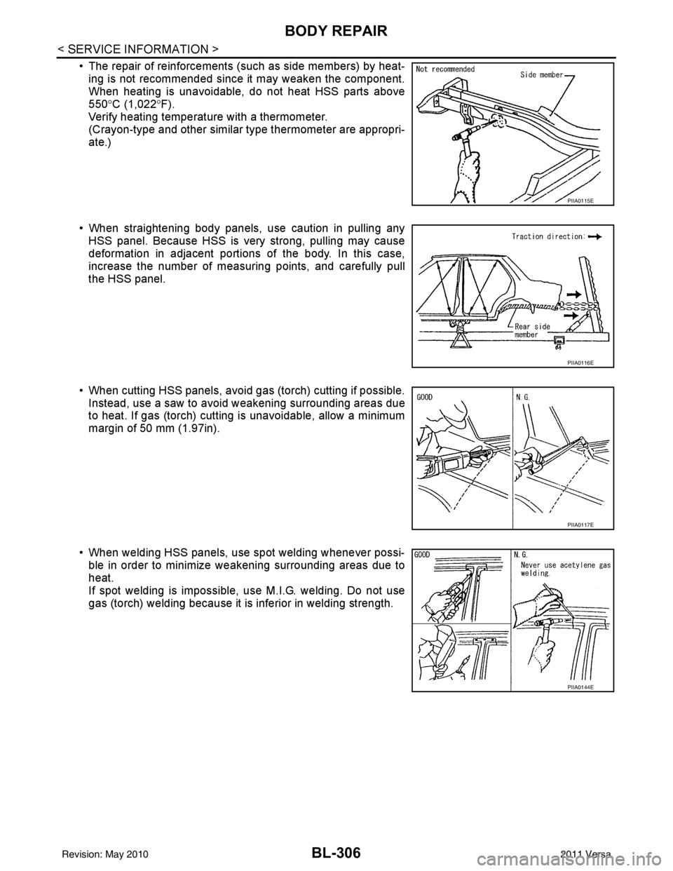
• The repair of reinforcements (such as side members) by heat-ing is not recommended since it may weaken the component.
When heating is unavoidable, do not heat HSS parts above
550° C (1,022° F).
Verify heating temperature with a thermometer.
(Crayon-type and other similar type thermometer are appropri-
ate.)
• When straightening body panels, use caution in pulling any HSS panel. Because HSS is very strong, pulling may cause
deformation in adjacent portions of the body. In this case,
increase the number of measuring points, and carefully pull
the HSS panel.
• When cutting HSS panels, avoid gas (torch) cutting if possible. Instead, use a saw to avoid weakening surrounding areas due
to heat. If gas (torch) cutting is unavoidable, allow a minimum
margin of 50 mm (1.97in).
• When welding HSS panels, use spot welding whenever possi- ble in order to minimize weakening surrounding areas due to
heat.
If spot welding is impossible, use M.I.G. welding. Do not use
gas (torch) welding because it is inferior in welding strength.
PIIA0115E
PIIA0116E
PIIA0117E
PIIA0144E
Revision: May 2010 2011 Versa
Page 820 of 3787
BL-310
< SERVICE INFORMATION >
BODY REPAIR
Sedan
1. Body side outer2. Front pillar lower reinforcement 3. Body side insulation (foam) front pil-
lar
4. Roof panel assembly 5. Body side insulation (Foam) rear
roof rail 6. Rear roof rail assembly
7. Body side insulation strip, center pil- lar 8. Body side insulation strip, rear pillar
lower 9. Body side insulation strip, rear pillar
upper
LIIA2665E
Revision: May 2010 2011 Versa
Page 821 of 3787
BODY REPAIRBL-311
< SERVICE INFORMATION >
C
DE
F
G H
J
K L
M A
B
BL
N
O P
Replacement OperationINFOID:0000000005929456
DESCRIPTION
1. Body side outer 2. Front pillar lower reinforcement 3. Body side insulation (foam) front pil-
lar
4. Parcel shelf 5. Body side insulation (Foam) rear pil-
lar 6. Rear body side inner
7. Body side insulation strip, center pil- lar 8. Body side insulation strip, rear pillar
lower 9. Body side insulation (foam) roof side
LIIA2891E
Revision: May 2010
2011 Versa
Page 824 of 3787

BL-314
< SERVICE INFORMATION >
BODY REPAIR
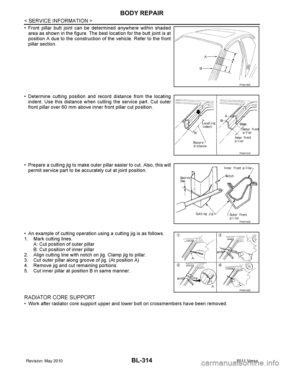
• Front pillar butt joint can be determined anywhere within shadedarea as shown in the figure. The best location for the butt joint is at
position A due to the construction of the vehicle. Refer to the front
pillar section.
• Determine cutting position and record distance from the locating indent. Use this distance when cutt ing the service part. Cut outer
front pillar over 60 mm above inner front pillar cut position.
• Prepare a cutting jig to make outer pillar easier to cut. Also, this will permit service part to be accurately cut at joint position.
• An example of cutting operation using a cutting jig is as follows.
1. Mark cutting lines. A: Cut position of outer pillar
B: Cut position of inner pillar
2. Align cutting line with notch on jig. Clamp jig to pillar.
3. Cut outer pillar along groove of jig. (At position A)
4. Remove jig and cut remaining portions.
5. Cut inner pillar at position B in same manner.
RADIATOR CORE SUPPORT
• Work after radiator core support upper and lower bolt on crossmembers have been removed.
PIIA0150E
PIIA0151E
PIIA0152E
PIIA0153E
Revision: May 2010 2011 Versa
Page 826 of 3787
BL-316
< SERVICE INFORMATION >
BODY REPAIR
HOODLEDGE RH
• Work after radiator core support upper and lower have been removed.
Change Parts�z Hoodledge reinforcement assembly �zFront strut housing �zFender bracket
�z Cowl top side upper �zHoodledge upper �zHoodledge connector
LIIA2893E
Revision: May 2010 2011 Versa
Page 827 of 3787
BODY REPAIRBL-317
< SERVICE INFORMATION >
C
DE
F
G H
J
K L
M A
B
BL
N
O P
FRONT SIDE MEMBER
• Work after hoodledge and radiator core support have been removed.
Change Parts �z Hoodledge reinforcement assembly �zFront strut housing �zFender bracket
�z Cowl top side upper �zHoodledge upper �zHoodledge connector
LIIA2894E
Revision: May 2010 2011 Versa