2011 NISSAN TIIDA RON 91
[x] Cancel search: RON 91Page 848 of 3787

BR-1
BRAKES
C
DE
G H
I
J
K L
M
SECTION BR
A
B
BR
N
O P
CONTENTS
BRAKE SYSTEM
SERVICE INFORMATION .. ..........................2
PRECAUTIONS .............................................. .....2
Precaution for Supplemental Restraint System
(SRS) "AIR BAG" and "SEAT BELT PRE-TEN-
SIONER" ............................................................. ......
2
Precaution Necessary for Steering Wheel Rota-
tion After Battery Disconnect ............................... ......
2
Precaution for Brake System ....................................3
PREPARATION ...................................................4
Special Service Tool ........................................... ......4
Commercial Service Tool ..........................................4
NOISE, VIBRATION AND HARSHNESS
(NVH) TROUBLESHOOTING .............................
5
NVH Troubleshooting Chart ................................ ......5
BRAKE PEDAL .............................................. .....6
Inspection and Adjustment .................................. ......6
Removal and Installation ...........................................7
BRAKE FLUID ................................................ .....9
On Board Inspection ........................................... ......9
Drain and Refill ..........................................................9
Bleeding Brake System .............................................9
BRAKE TUBE AND HOSE ................................11
Hydraulic Circuit .................................................. ....11
Front Brake Tube and Hose ....................................12
Rear Brake Tube and Hose ....................................12
Inspection After Installation .....................................13
DUAL PROPORTIONING VALVE .....................14
Removal and Installation .........................................14
Inspection ............................................................ ....14
BRAKE MASTER CYLINDER ........................ ....15
On-Board Inspection ........................................... ....15
Removal and Installation ..................................... ....15
Disassembly and Assembly .....................................16
BRAKE BOOSTER ...........................................20
On Board Inspection ............................................ ....20
Removal and Installation .........................................21
VACUUM LINES ...............................................23
Component ..............................................................23
Removal and Installation .........................................23
Inspection ................................................................23
FRONT DISC BRAKE .......................................25
On Board Inspection ............................................ ....25
Component ..............................................................25
Removal and Installation of Brake Pad ...................26
Removal and Installation of Brake Caliper Assem-
bly ........................................................................ ....
30
Disassembly and Assembly of Brake Caliper As-
sembly .....................................................................
31
Brake Burnishing Procedure ....................................34
REAR DRUM BRAKE .......................................35
Component .......................................................... ....35
Removal and Installation of Drum Brake Assembly
....
36
Removal and Installation of Wheel Cylinder ............39
Disassembly and Assembly of Wheel Cylinder .......39
SERVICE DATA AND SPECIFICATIONS
(SDS) .................................................................
40
General Specification ..............................................40
Brake Pedal .............................................................41
Check Valve ............................................................41
Brake Booster ..........................................................42
Front Disc Brake ......................................................42
Rear Drum Brake .....................................................42
Revision: May 2010 2011 Versa
Page 849 of 3787
BR-2
< SERVICE INFORMATION >
PRECAUTIONS
SERVICE INFORMATION
PRECAUTIONS
Precaution for Supplemental Restraint System (SRS) "AIR BAG" and "SEAT BELT
PRE-TENSIONER"
INFOID:0000000005928385
The Supplemental Restraint System such as “A IR BAG” and “SEAT BELT PRE-TENSIONER”, used along
with a front seat belt, helps to reduce the risk or severity of injury to the driver and front passenger for certain
types of collision. This system includes seat belt switch inputs and dual stage front air bag modules. The SRS
system uses the seat belt switches to determine the front air bag deployment, and may only deploy one front
air bag, depending on the severity of a collision and w hether the front occupants are belted or unbelted.
Information necessary to service the system safely is included in the SRS and SB section of this Service Man-
ual.
WARNING:
• To avoid rendering the SRS inopera tive, which could increase the risk of personal injury or death in
the event of a collision which would result in air bag inflation, all maintenance must be performed by
an authorized NISSAN/INFINITI dealer.
• Improper maintenance, including incorrect removal and installation of the SRS can lead to personal
injury caused by unintent ional activation of the system. For re moval of Spiral Cable and Air Bag
Module, see the SRS section.
• Do not use electrical test equipmen t on any circuit related to the SRS unless instructed to in this
Service Manual. SRS wiring harn esses can be identified by yellow and/or orange harnesses or har-
ness connectors.
PRECAUTIONS WHEN USING POWER TOOLS (AIR OR ELECTRIC) AND HAMMERS
WARNING:
• When working near the Airbag Diagnosis Sensor Unit or other Airbag System sensors with the Igni-
tion ON or engine running, DO NOT use air or electri c power tools or strike near the sensor(s) with a
hammer. Heavy vibration could activate the sensor( s) and deploy the air bag(s), possibly causing
serious injury.
• When using air or electric power tools or hammers , always switch the Ignition OFF, disconnect the
battery, and wait at least 3 minu tes before performing any service.
Precaution Necessary for Steering W heel Rotation After Battery Disconnect
INFOID:0000000005928386
NOTE:
• This Procedure is applied only to models with Intelligent Key system and NATS (NISSAN ANTI-THEFT SYS-
TEM).
• Remove and install all control units after disconnecting both battery cables with the ignition knob in the
″LOCK ″ position.
• Always use CONSULT-III to perform self-diagnosis as a part of each function inspection after finishing work.
If DTC is detected, perform trouble diagnosis according to self-diagnostic results.
For models equipped with the Intelligent Key system and NATS, an electrically controlled steering lock mech-
anism is adopted on the key cylinder.
For this reason, if the battery is disconnected or if the battery is discharged, the steering wheel will lock and
steering wheel rotation will become impossible.
If steering wheel rotation is required when battery pow er is interrupted, follow the procedure below before
starting the repair operation.
OPERATION PROCEDURE
1. Connect both battery cables. NOTE:
Supply power using jumper cables if battery is discharged.
2. Use the Intelligent Key or mechanical key to turn the ignition switch to the ″ACC ″ position. At this time, the
steering lock will be released.
3. Disconnect both battery cables. The steering lock will remain released and the steering wheel can be rotated.
4. Perform the necessary repair operation.
Revision: May 2010 2011 Versa
Page 857 of 3787

BR-10
< SERVICE INFORMATION >
BRAKE FLUID
3. With brake pedal depressed, loosen bleed valve to let the air out, and then tighten it immediately.
4. Repeat steps 2, 3 until no more air comes out.
5. Tighten bleed valve to specified torque. Refer to BR-25, "
Component" (front disc brake), BR-35, "Compo-
nent" (rear drum brake).
6. Following the steps 1 to 5 above, with master cylinder reservoir tank filled at least half way, bleed air from
the rear right, front left, rear left, and front right brake, in that order.
Revision: May 2010 2011 Versa
Page 858 of 3787
BRAKE TUBE AND HOSEBR-11
< SERVICE INFORMATION >
C
DE
G H
I
J
K L
M A
B
BR
N
O P
BRAKE TUBE AND HOSE
Hydraulic CircuitINFOID:0000000005928396
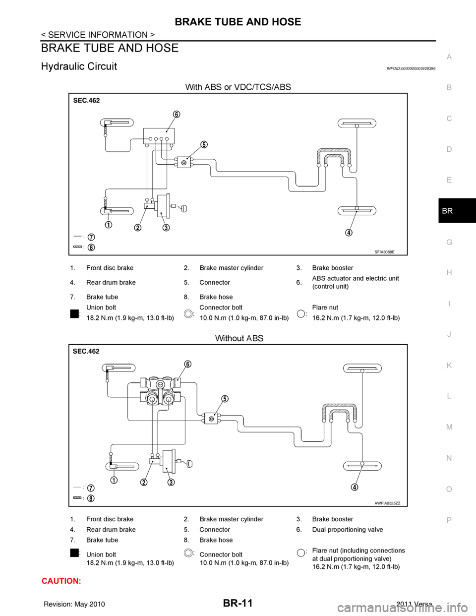
With ABS or VDC/TCS/ABS
Without ABS
CAUTION:
SFIA3068E
1. Front disc brake 2. Brake master cylinder3. Brake booster
4. Rear drum brake 5. Connector6.ABS actuator and electric unit
(control unit)
7. Brake tube 8. Brake hose
: Union bolt
:Connector bolt
:Flare nut
18.2 N.m (1.9 kg-m, 13.0 ft-lb) 10.0 N.m (1.0 kg-m, 87.0 in-lb) 16.2 N.m (1.7 kg-m, 12.0 ft-lb)
AWFIA0525ZZ
1. Front disc brake 2. Brake master cylinder3. Brake booster
4. Rear drum brake 5. Connector6. Dual proportioning valve
7. Brake tube 8. Brake hose
: Union bolt
18.2 N.m (1.9 kg-m, 13.0 ft-lb) :
Connector bolt
10.0 N.m (1.0 kg-m, 87.0 in-lb) :
Flare nut (including connections
at dual proportioning valve)
16.2 N.m (1.7 kg-m, 12.0 ft-lb)
Revision: May 2010
2011 Versa
Page 859 of 3787
BR-12
< SERVICE INFORMATION >
BRAKE TUBE AND HOSE
• All tubes and hoses must be free from excessive bending, twisting and pulling.
• Make sure there is no interference with other part s when turning steering both clockwise and coun-
terclockwise.
• Brake tubes and hoses are an important safety part. Always disassemble the parts and retighten
their fittings, if a brake fluid leak is detected. Replace applicable part with a new one, if damaged part
is detected.
• Be careful not to splash brake fluid on painted areas; it may cause paint damage. If brake fluid is
splashed on painted surfaces of body , immediately wipe them with cloth and then wash it away with
water.
• Do not bend or twist brake hose sharply, or strongly pull it.
• When removing components, cover brake line connect ions so that dirt, dust, or other foreign mat-
ters do not get in.
• Refill using recommended brake fluid. Refer to MA-14, "
Fluids and Lubricants".
• Never reuse drained brake fluid.
Front Brake Tube and HoseINFOID:0000000005928397
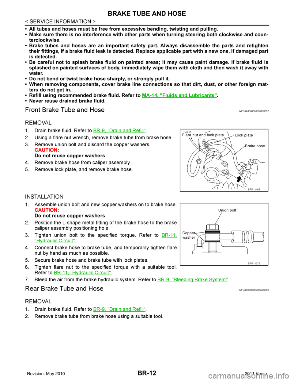
REMOVAL
1. Drain brake fluid. Refer to BR-9, "Drain and Refill".
2. Using a flare nut wrench, remove brake tube from brake hose.
3. Remove union bolt and discard the copper washers. CAUTION:
Do not reuse copper washers
4. Remove brake hose from caliper assembly.
5. Remove lock plate, and remove brake hose.
INSTALLATION
1. Assemble union bolt and new copper washers on to brake hose. CAUTION:
Do not reuse copper washers
2. Position the L-shape metal fitting of the brake hose to the brake caliper assembly positioning hole.
3. Tighten union bolt to the specified torque. Refer to BR-11,
"Hydraulic Circuit".
4. Connect brake hose to brake tube, and temporarily tighten flare nut by hand as much as possible.
5. Secure brake hose and brake tube with lock plates.
6. Tighten flare nut to the specified torque with a suitable tool. Refer to BR-11, "
Hydraulic Circuit".
7. Bleed the air from the brake hydraulic system. Refer to BR-9, "
Bleeding Brake System".
Rear Brake Tube and HoseINFOID:0000000005928398
REMOVAL
1. Drain brake fluid. Refer to BR-9, "Drain and Refill".
2. Remove brake tube from brake hose using a suitable tool.
SFIA1118E
SFIA1137E
Revision: May 2010 2011 Versa
Page 861 of 3787
BR-14
< SERVICE INFORMATION >
DUAL PROPORTIONING VALVE
DUAL PROPORTIONING VALVE
Removal and InstallationINFOID:0000000005928400
Removal
1. Remove the cowl top. Refer to EI-24, "Removal and Installation".
2. Disconnect brake lines from dual proportioning valve. • Mark brake lines for installation.
3. Remove dual proportioning valve bolt and dual proportioning valve.
4. Remove two bolts and bracket.
Installation
Installation is in the reverse order of removal.
• When installing brake lines to the dual proportioning valve, tighten to specifications. Refer to BR-11,
"Hydraulic Circuit".
InspectionINFOID:0000000005928401
CAUTION:
• Carefully monitor brake fluid level at master cylinder.
• Use the recommended new brake fluid. Refer to MA-14, "
Fluids and Lubricants".
• Be careful not to splash brake fluid on painted areas; it may cause paint damage. If brake fluid is
splashed on paint areas, wash it away with water immediately.
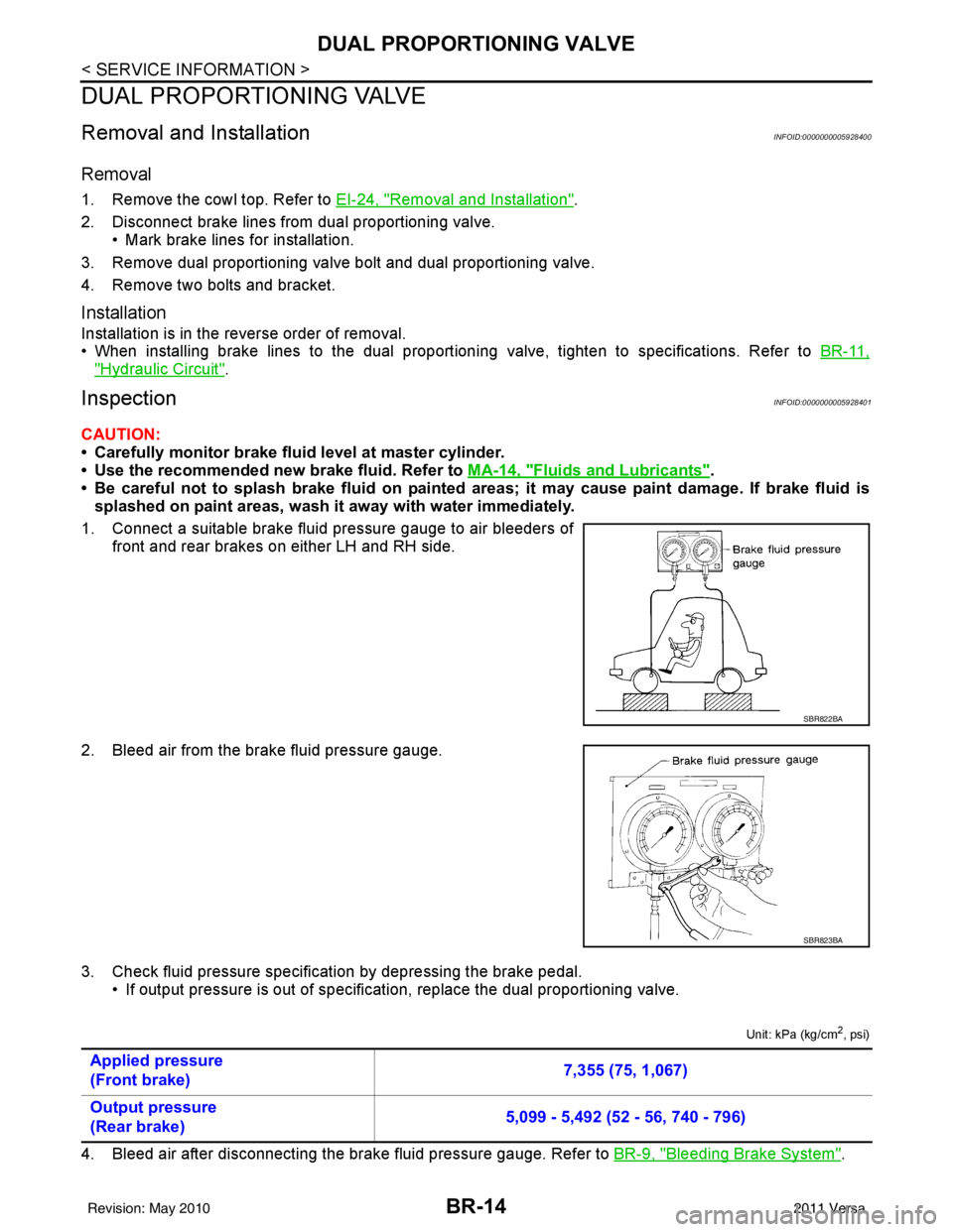
1. Connect a suitable brake fluid pressure gauge to air bleeders of front and rear brakes on either LH and RH side.
2. Bleed air from the brake fluid pressure gauge.
3. Check fluid pressure specific ation by depressing the brake pedal.
• If output pressure is out of specification, replace the dual proportioning valve.
Unit: kPa (kg/cm2, psi)
4. Bleed air after disconnecting the brake fluid pressure gauge. Refer to BR-9, "Bleeding Brake System".
SBR822BA
SBR823BA
Applied pressure
(Front brake) 7,355 (75, 1,067)
Output pressure
(Rear brake) 5,099 - 5,492 (52 - 56, 740 - 796)
Revision: May 2010
2011 Versa
Page 872 of 3787
FRONT DISC BRAKEBR-25
< SERVICE INFORMATION >
C
DE
G H
I
J
K L
M A
B
BR
N
O P
FRONT DISC BRAKE
On Board InspectionINFOID:0000000005928410
PAD WEAR INSPECTION
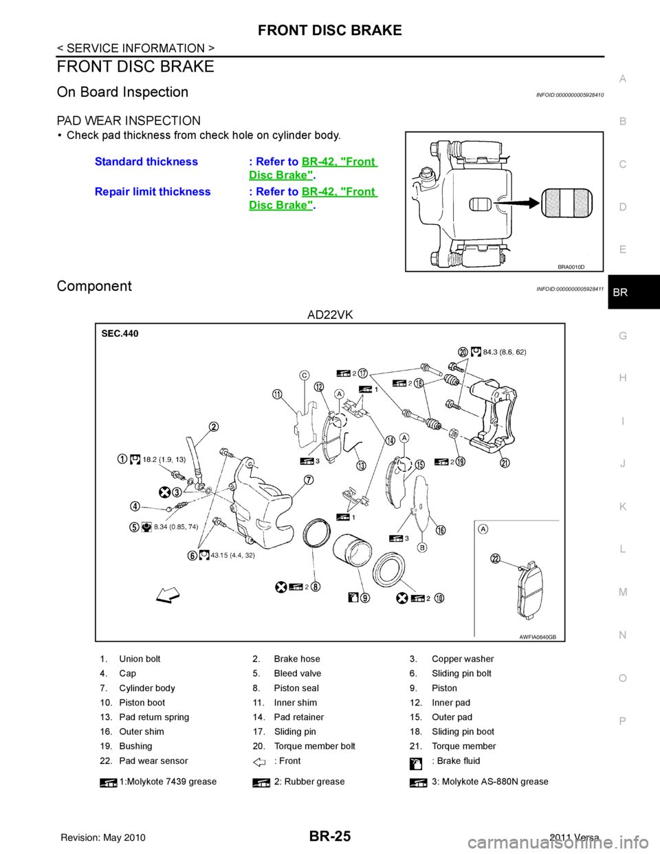
• Check pad thickness from check hole on cylinder body.
ComponentINFOID:0000000005928411
AD22VK
Standard thickness : Refer to BR-42, "Front
Disc Brake".
Repair limit thickness : Refer to BR-42, "
Front
Disc Brake".
BRA0010D
AWFIA0640GB
1. Union bolt2. Brake hose 3. Copper washer
4. Cap 5. Bleed valve 6. Sliding pin bolt
7. Cylinder body 8. Piston seal 9. Piston
10. Piston boot 11. Inner shim 12. Inner pad
13. Pad return spring 14. Pad retainer 15. Outer pad
16. Outer shim 17. Sliding pin 18. Sliding pin boot
19. Bushing 20. Torque member bolt 21. Torque member
22. Pad wear sensor : Front: Brake fluid
1:Molykote 7439 grease 2: Rubber grease 3: Molykote AS-880N grease
Revision: May 2010 2011 Versa
Page 873 of 3787
BR-26
< SERVICE INFORMATION >
FRONT DISC BRAKE
CLZ25VF
CAUTION:
• Clean dust on caliper and brake pad with a vacuum dust collector. Do not blow with compressed air.
• While removing brake pad or cylinder body, do not depress brake pedal because piston will pop out.
• It is not necessary to remove torque member mounting bolts and brake hose except for disassembly
or replacement of caliper assembly. In this case, hang cylinder body with a wire so that brake hose is
not under tension.
• Do not damage piston boot.
• If any shim is subject to serious corrosion, replace it with a new one.
• Keep rotor free from brake fluid.
• When replacing brake pad, replace shim with a new one.
Removal and Installation of Brake PadINFOID:0000000005928412
AD22VK
Removal
1. Partially drain brake fluid reservoir. Refer to BR-9, "Drain and Refill".
2. Remove front wheel and tire using power tools.
AWFIA0641GB
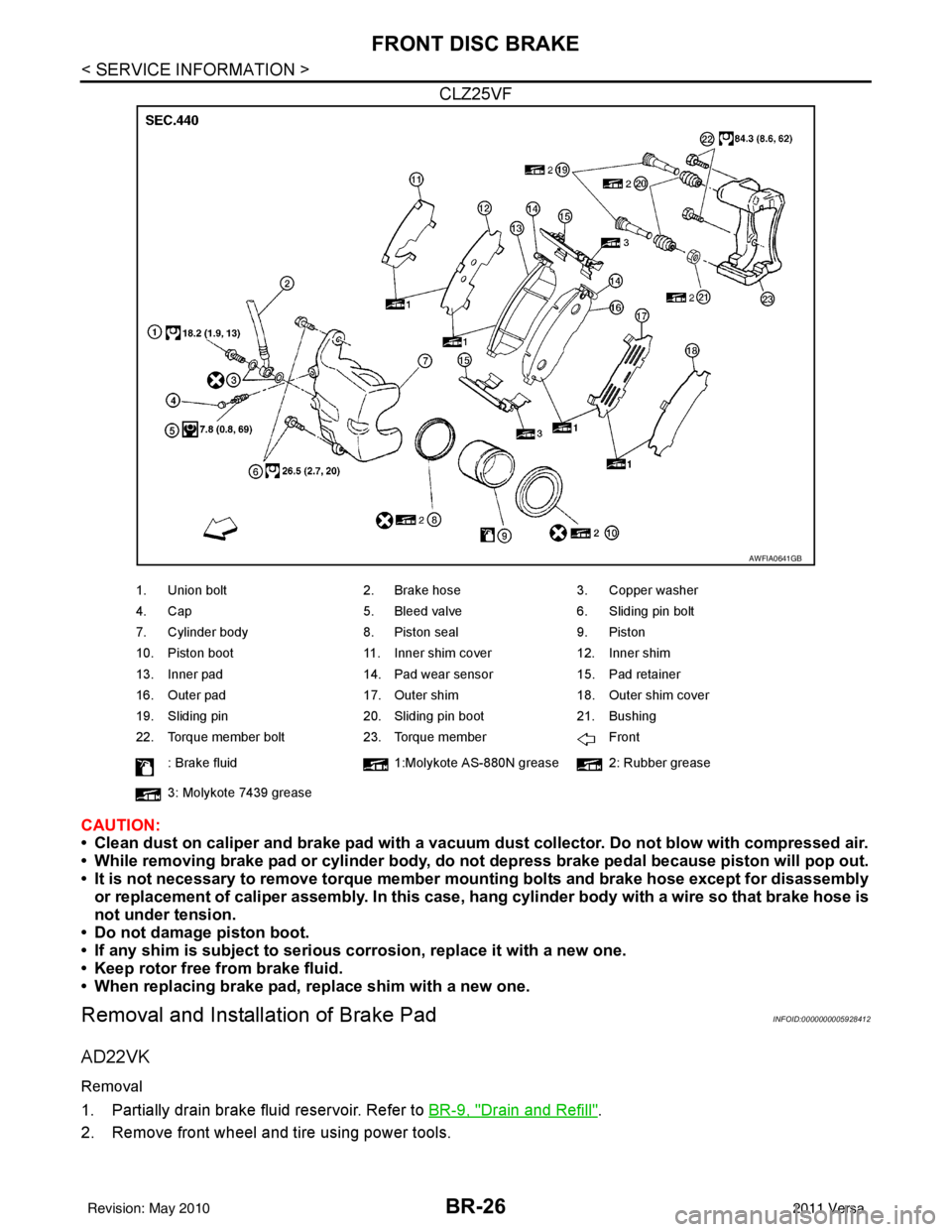
1. Union bolt 2. Brake hose3. Copper washer
4. Cap 5. Bleed valve6. Sliding pin bolt
7. Cylinder body 8. Piston seal9. Piston
10. Piston boot 11. Inner shim cover12. Inner shim
13. Inner pad 14. Pad wear sensor15. Pad retainer
16. Outer pad 17. Outer shim18. Outer shim cover
19. Sliding pin 20. Sliding pin boot21. Bushing
22. Torque member bolt 23. Torque member Front
: Brake fluid 1:Molykote AS-880N grease 2: Rubber grease
3: Molykote 7439 grease
Revision: May 2010 2011 Versa