2011 NISSAN TIIDA washer fluid
[x] Cancel search: washer fluidPage 877 of 3787

BR-30
< SERVICE INFORMATION >
FRONT DISC BRAKE
Removal and Installation of Brake Caliper Assembly
INFOID:0000000005928413
REMOVAL
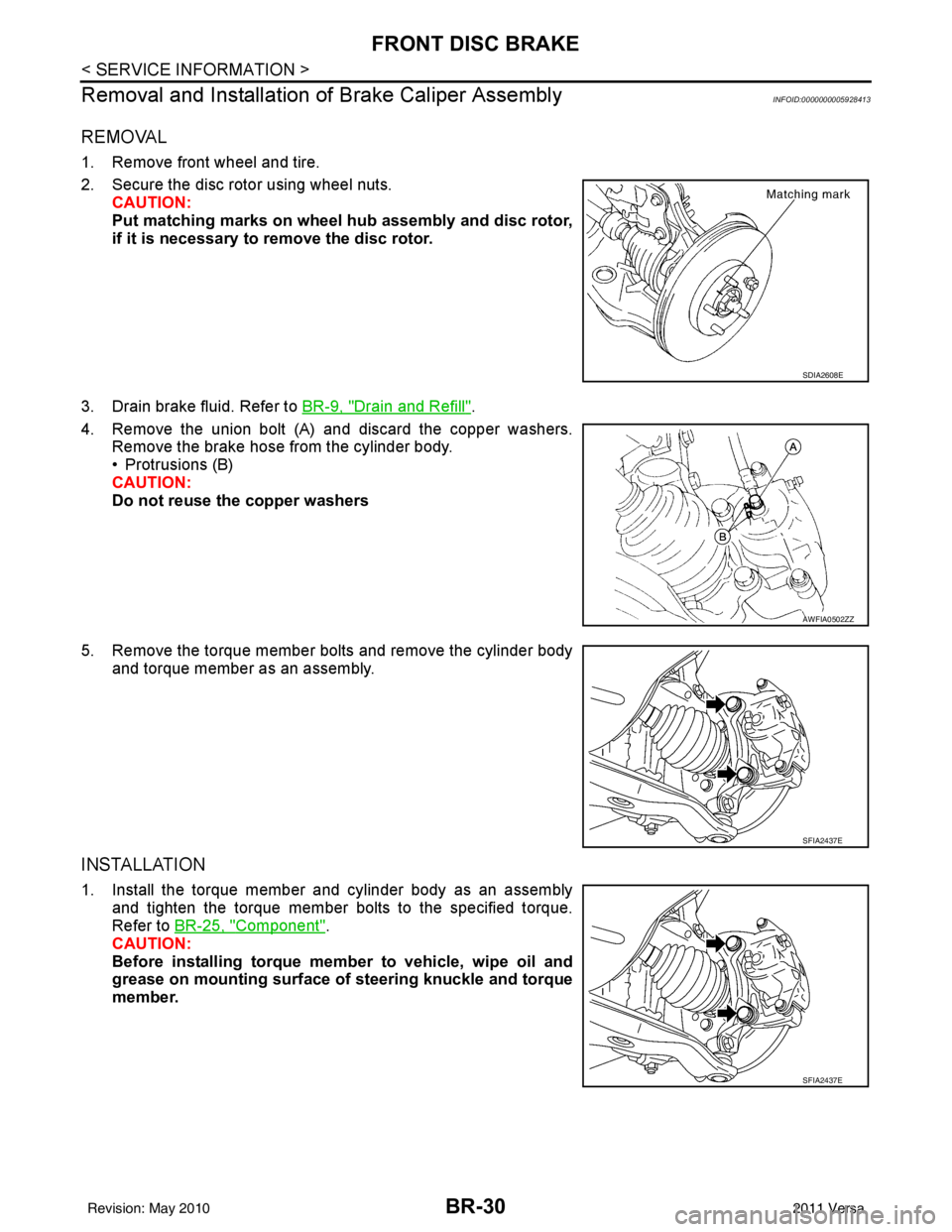
1. Remove front wheel and tire.
2. Secure the disc rotor using wheel nuts.
CAUTION:
Put matching marks on wheel hub assembly and disc rotor,
if it is necessary to remove the disc rotor.
3. Drain brake fluid. Refer to BR-9, "
Drain and Refill".
4. Remove the union bolt (A) and discard the copper washers. Remove the brake hose from the cylinder body.
• Protrusions (B)
CAUTION:
Do not reuse the copper washers
5. Remove the torque member bolts and remove the cylinder body and torque member as an assembly.
INSTALLATION
1. Install the torque member and cylinder body as an assemblyand tighten the torque member bolts to the specified torque.
Refer to BR-25, "
Component".
CAUTION:
Before installing torque member to vehicle, wipe oil and
grease on mounting surface of steering knuckle and torque
member.
SDIA2608E
AWFIA0502ZZ
SFIA2437E
SFIA2437E
Revision: May 2010 2011 Versa
Page 878 of 3787

FRONT DISC BRAKEBR-31
< SERVICE INFORMATION >
C
DE
G H
I
J
K L
M A
B
BR
N
O P
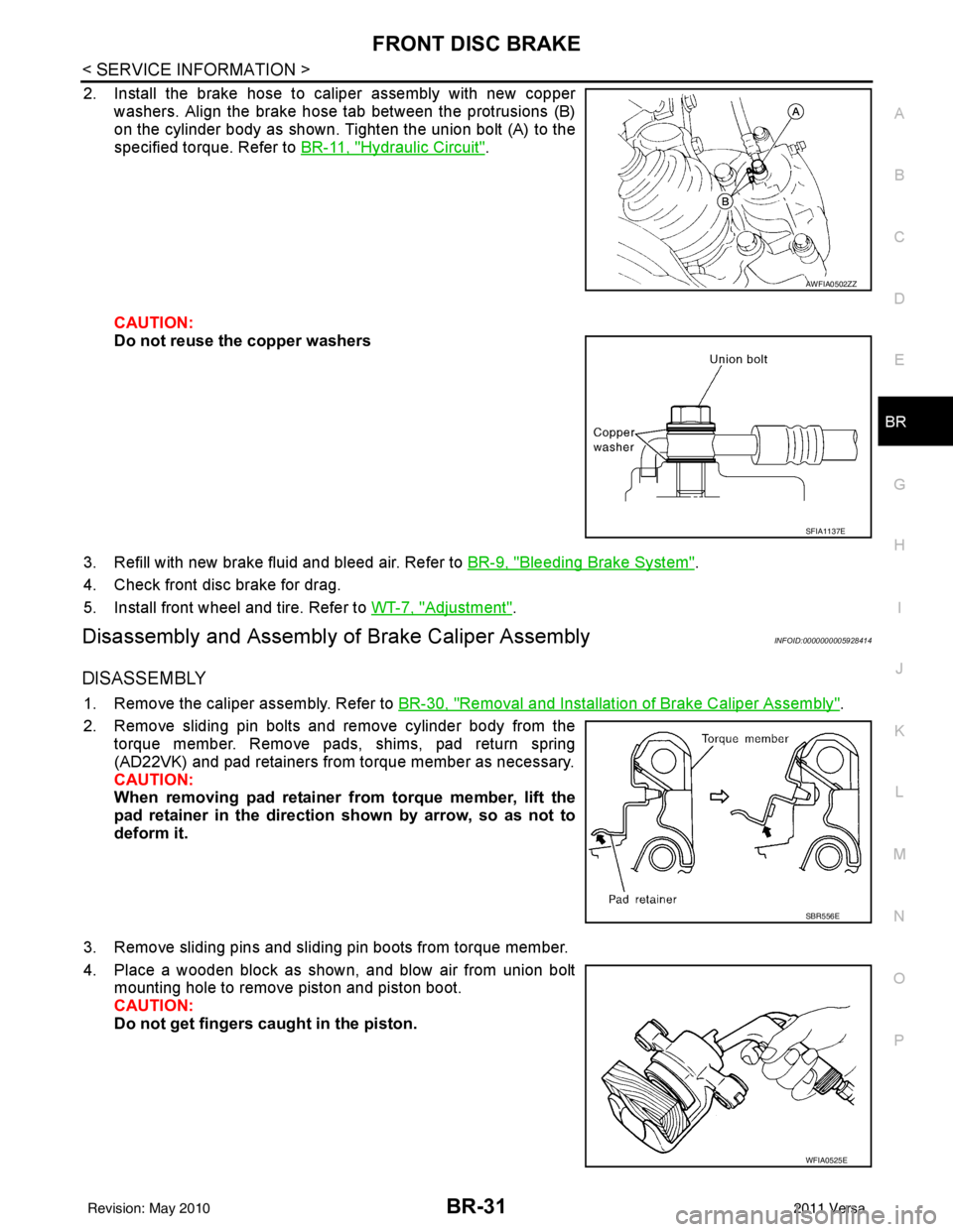
2. Install the brake hose to caliper assembly with new copper washers. Align the brake hose tab between the protrusions (B)
on the cylinder body as shown. Tighten the union bolt (A) to the
specified torque. Refer to BR-11, "
Hydraulic Circuit".
CAUTION:
Do not reuse the copper washers
3. Refill with new brake fluid and bleed air. Refer to BR-9, "
Bleeding Brake System".
4. Check front disc brake for drag.
5. Install front wheel and tire. Refer to WT-7, "
Adjustment".
Disassembly and Assembly of Brake Caliper AssemblyINFOID:0000000005928414
DISASSEMBLY
1. Remove the caliper assembly. Refer to BR-30, "Removal and Installation of Brake Caliper Assembly".
2. Remove sliding pin bolts and remove cylinder body from the torque member. Remove pads, shims, pad return spring
(AD22VK) and pad retainers from torque member as necessary.
CAUTION:
When removing pad retainer from torque member, lift the
pad retainer in the direction shown by arrow, so as not to
deform it.
3. Remove sliding pins and sliding pin boots from torque member.
4. Place a wooden block as shown, and blow air from union bolt mounting hole to remove piston and piston boot.
CAUTION:
Do not get fingers caught in the piston.
AWFIA0502ZZ
SFIA1137E
SBR556E
WFIA0525E
Revision: May 2010 2011 Versa
Page 1235 of 3787
![NISSAN TIIDA 2011 Service Repair Manual CVT-180
< SERVICE INFORMATION >[RE0F08B]
TRANSAXLE ASSEMBLY
TRANSAXLE ASSEMBLY
Removal and InstallationINFOID:0000000005928976
COMPONENTS
REMOVAL
WARNING:
Never remove the radiator cap when the engine NISSAN TIIDA 2011 Service Repair Manual CVT-180
< SERVICE INFORMATION >[RE0F08B]
TRANSAXLE ASSEMBLY
TRANSAXLE ASSEMBLY
Removal and InstallationINFOID:0000000005928976
COMPONENTS
REMOVAL
WARNING:
Never remove the radiator cap when the engine](/manual-img/5/57396/w960_57396-1234.png)
CVT-180
< SERVICE INFORMATION >[RE0F08B]
TRANSAXLE ASSEMBLY
TRANSAXLE ASSEMBLY
Removal and InstallationINFOID:0000000005928976
COMPONENTS
REMOVAL
WARNING:
Never remove the radiator cap when the engine is hot. Serious burns coul
d occur from high pressure
coolant escaping from the radiator.
CAUTION:
• Perform this step engine is cold.
• When replacing TCM and transaxle assembly as a set, replace transaxle assembly first and then replace TCM. Refer to CVT-8, "
Service After Replacing TCM and Transaxle Assembly".
1. Remove the engine and transaxle as an assembly. Refer to EM-197, "
Removal and Installation".
1. CVT fluid level gauge2. CVT fluid charging pipe 3. O-ring
4. Copper washer 5. Fluid cooler tube6. Transaxle assembly
7. Engine mounting bracket (LH) 8. Air breather hose A. Refer to "INSTALLATION".
WCIA0614E
Revision: May 2010 2011 Versa
Page 1236 of 3787
![NISSAN TIIDA 2011 Service Repair Manual TRANSAXLE ASSEMBLYCVT-181
< SERVICE INFORMATION > [RE0F08B]
D
E
F
G H
I
J
K L
M A
B
CVT
N
O P
2. Disconnect the primary speed sensor (A) and the secondary
speed sensor connector (B) and CVT unit conn NISSAN TIIDA 2011 Service Repair Manual TRANSAXLE ASSEMBLYCVT-181
< SERVICE INFORMATION > [RE0F08B]
D
E
F
G H
I
J
K L
M A
B
CVT
N
O P
2. Disconnect the primary speed sensor (A) and the secondary
speed sensor connector (B) and CVT unit conn](/manual-img/5/57396/w960_57396-1235.png)
TRANSAXLE ASSEMBLYCVT-181
< SERVICE INFORMATION > [RE0F08B]
D
E
F
G H
I
J
K L
M A
B
CVT
N
O P
2. Disconnect the primary speed sensor (A) and the secondary
speed sensor connector (B) and CVT unit connector (C). Refer
to CVT-9, "
Removal and Installation Procedure for CVT Unit
Connector".
3. Remove the harness from the transaxle.
4. Remove the four drive plate to torque converter nuts. NOTE:
Rotate the crankshaft clockwise as viewed from front of engine
for access to drive plate to torque converter nuts.
5. Put matching marks on the drive plate and torque converter alignment stud. CAUTION:
For matching marks, use paint. Never dama ge the drive plate or torque converter.
6. Remove the transaxle to engine and engine to transaxle bolts.
7. Separate the transaxle from the engine.
8. If necessary, remove the following from the transaxle: • CVT fluid charging pipe
• Engine mounting bracket (LH)
• Fluid cooler tubes
• Air breather hose
• Any necessary brackets
INSTALLATION
Installation is in the reverse order of removal.
CAUTION:
• When replacing an engine or transmission you must make sure any dowels are installed correctlyduring re-assembly.
• Improper alignment caused by missing dowels may cause vibration, oil leaks or breakage of drive train components.
• Do not reuse O-rings and copper washers.
• When turning crankshaft, turn it clockwise as viewed from the front of the engine.
• When tightening the nuts for the torque converter while securing the crankshaft pulley bolt, be sure
to confirm the tightening torque of the crankshaft pulley bolt. Refer to EM-159
.
• After converter is installed to drive plate, ro tate crankshaft several turns to check that transaxle
rotates freely without binding.
AWDIA0661GB
WCIA0616E
Revision: May 2010 2011 Versa
Page 1250 of 3787

COMBINATION METERSDI-11
< SERVICE INFORMATION >
C
DE
F
G H
I
J
L
M A
B
DI
N
O P
Self-Diagnosis Mode of Combination MeterINFOID:0000000005929166
SELF-DIAGNOSIS MODE FUNCTION
• Self-diagnosis can check for continuity between meter control circuit and each meter (speedometer, tachom- eter and fuel gauge).
• Self-diagnosis can check for odo/trip meter and A/T indi cator (with A/T) or CVT indicator (with CVT) seg-
ment, low-fuel level warning lamp, low water temperature indicator lamp, and high water temperature warn-
ing lamp.
OPERATION PROCEDURE
1. Turn the ignition switch ON, and switch the odo/trip meter to “trip A” or “trip B”. NOTE:
13 B Illumination control switch (-) — —Refer to LT- 1 0 9 , "System Description" .
17 G Washer fluid level switch
(Canada models)
ONWasher fluid level low
0
Washer fluid level normal Battery voltage
21 BGround —— 0
22
23
24 V Fuel level sensor ground (-) ON —0
26 B Vehicle speed sensor ground
(without ABS or CVT) ON
— 0
27 G Battery power supply OFF— Battery voltage
28 SB Ignition switch ON or START ON —Battery voltage
29 GR Seat belt buckle switch RH ON Unfastened (ON)
0
Fastened (OFF) Battery voltage
30 G Stop lamp switch ONBrake pedal depressed
Battery voltage
Brake pedal released 0
31 V A/T N-range input (with A/T) ON Transmission gear selector lever
in N position
Battery voltage
Transmission gear selector lever
other than N position 0
32 W A/T P-range input (with A/T) ON Transmission gear selector lever
in P position
Battery voltage
Transmission gear selector lever
other than P position 0
33 Y A/T PN output (with A/T) ON Transmission gear selector lever
in P or N position
0
Transmission gear selector lever
other than P or N position Battery voltage
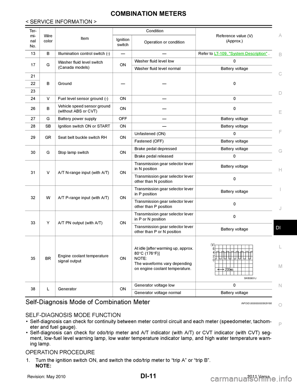
35 BR Engine coolant temperature
signal output
ONAt idle [after warming up, approx.
80
°C (176 °F)]
NOTE:
The waveforms vary depending
on engine coolant temperature.
38 L Generator ONGenerator voltage low
0
Generator voltage no rmal Battery voltage
Te r -
mi-
nal
No. Wire
color Item Condition
Reference value (V)
(Approx.)
Ignition
switch Operation or condition
SKIB3651J
Revision: May 2010
2011 Versa
Page 2435 of 3787
![NISSAN TIIDA 2011 Service Repair Manual OIL PAN (UPPER) AND OIL STRAINEREM-45
< ON-VEHICLE REPAIR > [HR16DE]
C
D
E
F
G H
I
J
K L
M A
EM
NP
O
• Press-fit to the dimensions specified.
CAUTION:
• Do not touch the grease applied to the oil NISSAN TIIDA 2011 Service Repair Manual OIL PAN (UPPER) AND OIL STRAINEREM-45
< ON-VEHICLE REPAIR > [HR16DE]
C
D
E
F
G H
I
J
K L
M A
EM
NP
O
• Press-fit to the dimensions specified.
CAUTION:
• Do not touch the grease applied to the oil](/manual-img/5/57396/w960_57396-2434.png)
OIL PAN (UPPER) AND OIL STRAINEREM-45
< ON-VEHICLE REPAIR > [HR16DE]
C
D
E
F
G H
I
J
K L
M A
EM
NP
O
• Press-fit to the dimensions specified.
CAUTION:
• Do not touch the grease applied to the oil seal lip.
• Be careful not to damage the rear oil seal mounting partof oil pan (upper) and cylinder block or the crankshaft.
• Install straight to make sure that oil seal does not curl or tilt.
d. After press-fitting the rear oil seal, completely wipe off any liquid gasket protruding to rear end surface side.
3. Install crankshaft sprocket, oil pump sprocket, oi l pump drive chain, and chain tensioner. Refer to EM-49,
"Exploded View".
4. Install timing chain and related parts. Refer to EM-49, "
Removal and Installation".
5. Install front cover and related parts. Refer to EM-49, "
Removal and Installation".
6. Install oil pan (lower). Refer to EM-39, "
Removal and Installation".
7. Install oil pan drain plug. • For installation direction of washer. Refer to EM-42, "
Component".
8. Installation of the remaining components is in the reverse order of removal. CAUTION:
Do not fill engine with engi ne oil until at least 30 minutes after oil pan is installed.
InspectionINFOID:0000000006413268
INSPECTION AFTER INSTALLATION
• Before starting engine, check oil/fluid levels incl uding engine coolant and engine oil. If less than required
quantity, fill to the specified level. Refer to MA-14, "
Fluids and Lubricants".
• Use procedure below to check for fuel leakage.
• Turn ignition switch ON (with engine stopped). With fuel pressure applied to fuel piping, check for fuel leak-
age at connection points.
• Start engine. With engine speed increased, check again for fuel leakage at connection points.
• Run engine to check for unusual noise and vibration.
• Warm up engine thoroughly to make sure there is no leak age of fuel, exhaust gas, or any oils/fluids including
engine oil and engine coolant.
• Bleed air from passages in lines and hoses, such as in cooling system.
• After cooling down engine, again check oil/fluid levels including engine oil and engine coolant. Refill to spec- ified level, if necessary.
• Summary of the inspection items:
*Power steering fluid, brake fluid, etc. 1. Rear oil seal
A. Rear end surface of cylinder block
PBIC3761E
Item
Before starting engine Engine runningAfter engine stopped
Engine coolant LevelLeakage Level
Engine oil LevelLeakage Level
Transmission/
transaxle fluid A/T and CVT Models
LeakageLevel/Leakage Leakage
M/T Models Level/Leakage LeakageLevel/Leakage
Other oils and fluids* LevelLeakage Level
Fuel LeakageLeakageLeakage
Exhaust gas —Leakage —
Revision: May 2010 2011 Versa
Page 2590 of 3787
![NISSAN TIIDA 2011 Service Repair Manual EM-200
< SERVICE INFORMATION >[MR18DE]
ENGINE ASSEMBLY
35. Separate the engine and the transaxle and mount the engine on a suitable engine stand. Refer to
AT-233
(A/T models), CVT-180, "Removal and I NISSAN TIIDA 2011 Service Repair Manual EM-200
< SERVICE INFORMATION >[MR18DE]
ENGINE ASSEMBLY
35. Separate the engine and the transaxle and mount the engine on a suitable engine stand. Refer to
AT-233
(A/T models), CVT-180, "Removal and I](/manual-img/5/57396/w960_57396-2589.png)
EM-200
< SERVICE INFORMATION >[MR18DE]
ENGINE ASSEMBLY
35. Separate the engine and the transaxle and mount the engine on a suitable engine stand. Refer to
AT-233
(A/T models), CVT-180, "Removal and Installation" (CVT models) or MT-61, "Removal and Installation"
(M/T models).
INSTALLATION
Installation is in the reverse order of removal.
Note the following during installation:
• When installation directions are specified, install parts according to the directions. Refer to EM-197, "
Com-
ponent".
• Do not allow engine oil to get on engine mounting insulator. Be careful not to damage engine mounting insu-
lator.
• Prior to installing the upper torque rod, apply a light coat of silicone lubricant (A) to the washer facing side of the bushing inner tube as
shown.
NOTE:
• Apply silicone lubricant (A) by dabbing the outward facing tubesurface with a sponge or suitable tool.
• Do not apply excess lubricant.
• Make sure that each mounting insulator is seated properly, and tighten nuts and bolts.
• Tighten engine mounting insulator (RH) bolts in the numerical order shown.
INSPECTION AFTER INSTALLATION
• Before starting engine, check oil/fluid levels incl uding engine coolant and engine oil. If less than required
quantity, fill to the specified level. Refer to MA-14, "
Fluids and Lubricants".
• Use procedure below to check for fuel leakage.
• Turn ignition switch ON (with engine stopped). With fuel pressure applied to fuel piping, check for fuel leak- age at connection points.
• Start engine. With engine speed increased, che ck again for fuel leakage at connection points.
• Run engine to check for unusual noise and vibration.
• Warm up engine thoroughly to make sure there is no leakage of fuel, exhaust gas, or any oils/fluids including
engine oil and engine coolant.
• Bleed air from passages in lines and hoses, such as in cooling system.
• After cooling down engine, again check oil/fluid levels including engine oil and engine coolant. Refill to spec- ified level, if necessary.
• Summary of the inspection items:
: Vehicle front
LBIA0470E
: Vehicle front
WBIA0785E
Item Before starting engine Engine runningAfter engine stopped
Engine coolant LevelLeakage Level
Engine oil LevelLeakage Level
Transmission/
transaxle fluid A/T and CVT Models
LeakageLevel/Leakage Leakage
M/T Models Level/Leakage LeakageLevel/Leakage
Revision: May 2010 2011 Versa
Page 2708 of 3787

GI-4
< SERVICE INFORMATION >
PRECAUTIONS
• Replace oil seals, gaskets, packings, O-rings, locking washers, cotter pins, self-locking nuts, etc. with new
ones.
• Replace inner and outer races of tapered roller bearings and needle bearings as a set.
• Arrange the disassembled parts in accordance with their assembled locations and sequence.
• Do not touch the terminals of electrical com ponents which use microcomputers (such as ECM).
Static electricity may damage internal electronic components.
• After disconnecting vacuum or air hoses, atta ch a tag to indicate the proper connection.
• Use only the fluids and lubricants specified in this manual.
• Use approved bonding agent, sealants or their equivalents when required.
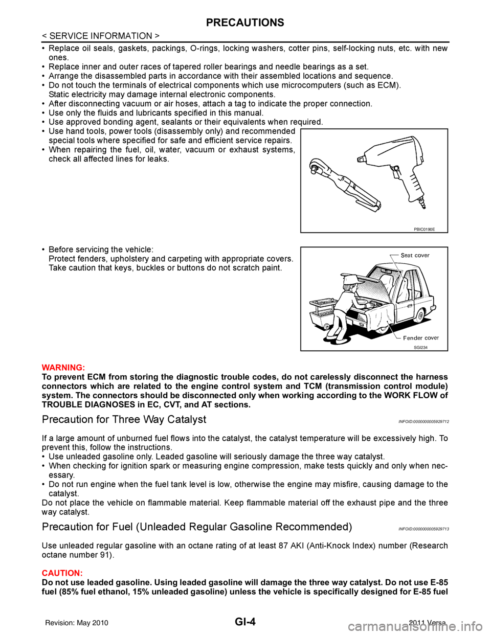
• Use hand tools, power tools (disassembly only) and recommended special tools where specified for safe and efficient service repairs.
• When repairing the fuel, oil, water, vacuum or exhaust systems, check all affected lines for leaks.
• Before servicing the vehicle: Protect fenders, upholstery and carpeting with appropriate covers.
Take caution that keys, buckles or buttons do not scratch paint.
WARNING:
To prevent ECM from storing the diagnostic tro uble codes, do not carelessly disconnect the harness
connectors which are related to the engine control system and TCM (transmission control module)
system. The connectors should be disconnected only when working according to the WORK FLOW of
TROUBLE DIAGNOSES in EC, CVT, and AT sections.
Precaution for Three Way CatalystINFOID:0000000005929712
If a large amount of unburned fuel flows into the catalyst , the catalyst temperature will be excessively high. To
prevent this, follow the instructions.
• Use unleaded gasoline only. Leaded gasoline will seriously damage the three way catalyst.
• When checking for ignition spark or measuring engine compression, make tests quickly and only when nec- essary.
• Do not run engine when the fuel tank level is low, otherwise the engine may misfire, causing damage to the
catalyst.
Do not place the vehicle on flammable material. Keep flammable material off the exhaust pipe and the three
way catalyst.
Precaution for Fuel (Unleade d Regular Gasoline Recommended)INFOID:0000000005929713
Use unleaded regular gasoline with an octane rating of at least 87 AKI (Anti-Knock Index) number (Research
octane number 91).
CAUTION:
Do not use leaded gasoline. Using leaded gasoline will damage the three way catalyst. Do not use E-85
fuel (85% fuel ethanol, 15% unleaded gasoline) unless the vehicle is specifically designed for E-85 fuel
PBIC0190E
SGI234
Revision: May 2010 2011 Versa