2011 NISSAN TIIDA washer fluid
[x] Cancel search: washer fluidPage 2713 of 3787

HOW TO USE THIS MANUALGI-9
< SERVICE INFORMATION >
C
DE
F
G H
I
J
K L
M B
GI
N
O P
SYMBOLS
How to Follow Trouble DiagnosisINFOID:0000000005929724
DESCRIPTION
NOTICE:
Trouble diagnoses indicate work procedures required to diagnose problems effectively. Observe the following
instructions before diagnosing.
1. Before performing trouble diagno ses, read the “Preliminary Check” , the “Symptom Chart” or the
“Work Flow”.
2. After repairs, re-check that the prob lem has been completely eliminated.
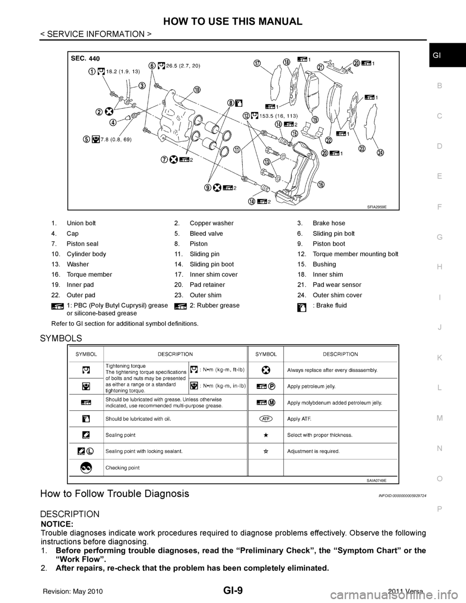
1. Union bolt 2. Copper washer3. Brake hose
4. Cap 5. Bleed valve6. Sliding pin bolt
7. Piston seal 8. Piston9. Piston boot
10. Cylinder body 11. Sliding pin12. Torque member mounting bolt
13. Washer 14. Sliding pin boot15. Bushing
16. Torque member 17. Inner shim cover18. Inner shim
19. Inner pad 20. Pad retainer21. Pad wear sensor
22. Outer pad 23. Outer shim24. Outer shim cover
1: PBC (Poly Butyl Cuprysil) grease
or silicone-based grease 2: Rubber grease
: Brake fluid
Refer to GI section for additional symbol definitions.
SFIA2959E
SAIA0749E
Revision: May 2010 2011 Versa
Page 3156 of 3787
![NISSAN TIIDA 2011 Service Repair Manual LU-8
< ON-VEHICLE MAINTENANCE >[HR16DE]
ENGINE OIL
4. Install oil pressure gauge and hose.
5. Start engine and warm it up to normal operating temperature.
6. Check oil pressure with engine running und NISSAN TIIDA 2011 Service Repair Manual LU-8
< ON-VEHICLE MAINTENANCE >[HR16DE]
ENGINE OIL
4. Install oil pressure gauge and hose.
5. Start engine and warm it up to normal operating temperature.
6. Check oil pressure with engine running und](/manual-img/5/57396/w960_57396-3155.png)
LU-8
< ON-VEHICLE MAINTENANCE >[HR16DE]
ENGINE OIL
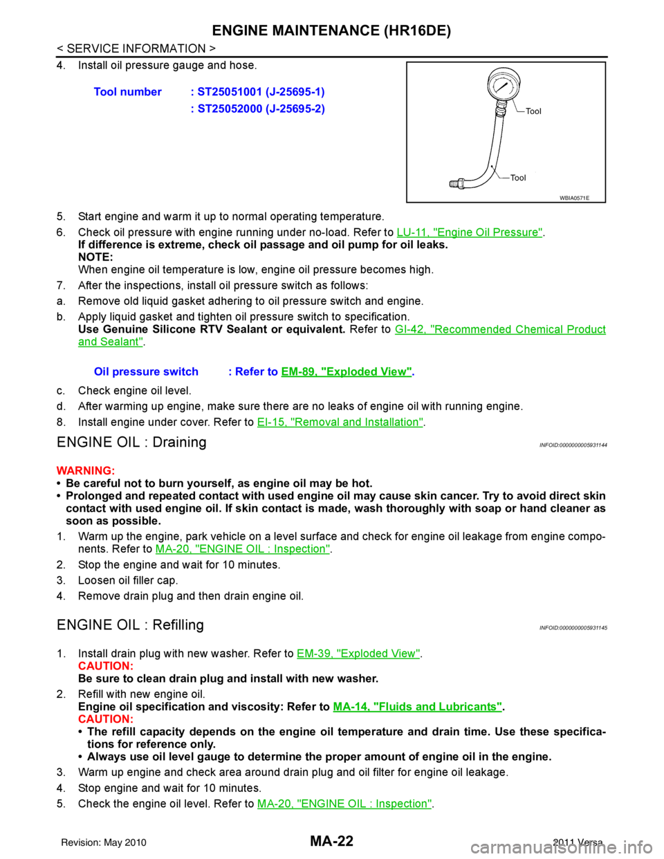
4. Install oil pressure gauge and hose.
5. Start engine and warm it up to normal operating temperature.
6. Check oil pressure with engine running under no-load. Refer to LU-11, "
Engine Oil Pressure".
If difference is extreme, check oil passage and oil pump for oil leaks.
NOTE:
When engine oil temperature is low, engine oil pressure becomes high.
7. After the inspections, install oil pressure switch as follows:
a. Remove old liquid gasket adhering to oil pressure switch and engine.
b. Apply liquid gasket and tighten oil pressure switch to specification. Use Genuine Silicone RTV Sealant or equivalent. Refer to GI-42, "
Recommended Chemical Product
and Sealant".
c. Check engine oil level.
d. After warming up engine, make sure there are no leaks of engine oil with running engine.
8. Install engine under cover. Refer to EI-15, "
Removal and Installation".
DrainingINFOID:0000000005928688
WARNING:
• Be careful not to burn yourself, as engine oil may be hot.
• Prolonged and repeated contact with used engine oil may cause ski n cancer. Try to avoid direct skin
contact with used engine oil. If skin contact is made, wash thoroughly with soap or hand cleaner as
soon as possible.
1. Warm up the engine, park vehicle on a level surface and check for engine oil leakage from engine compo- nents. Refer to LU-7, "
Inspection".
2. Stop the engine and wait for 10 minutes.
3. Loosen oil filler cap.
4. Remove drain plug and then drain engine oil.
RefillingINFOID:0000000005928689
1. Install drain plug with new washer. Refer to EM-39, "Exploded View".
CAUTION:
Be sure to clean drain plug and install with new washer.
2. Refill with new engine oil. Engine oil specification and viscosity: Refer to MA-14, "
Fluids and Lubricants".
CAUTION:
• The refill capacity depends on the engine oi l temperature and drain time. Use these specifica-
tions for reference only.
• Always use oil level gauge to determine the pr oper amount of engine oil in the engine.
3. Warm up engine and check area around drain plug and oil filter for engine oil leakage.
4. Stop engine and wait for 10 minutes.
5. Check the engine oil level. Refer to LU-7, "
Inspection".
Tool number : ST25051001 (J-25695-1)
: ST25052000 (J-25695-2)
WBIA0571E
Oil pressure switch : Refer to EM-89, "Exploded View".
Revision: May 2010 2011 Versa
Page 3185 of 3787

MA-14
< SERVICE INFORMATION >
RECOMMENDED FLUIDS AND LUBRICANTS
RECOMMENDED FLUIDS AND LUBRICANTS
Fluids and LubricantsINFOID:0000000005931134
*1: For further details, see “Engine Oil Recommendation”.
*2: If Genuine NISSAN gear oil is not available, API GL-4, Viscosity SAE 75W-85 may also be used as a temporary replacement. How-
ever, use Genuine NISSAN gear oil as soon as it is available.
*3: If Genuine NISSAN ge ar oil is not available, API GL-4, Viscosity SAE 75W-80 may be used as a temporary replacement. However
use Genuine NISSAN gear oil as soon as it is available.
*4: If Genuine NISSAN Matic S ATF is not available, Genuine NISSIAN Matic D ATF may also be used. Using automatic transmission
other than Genuine NISSAN Matic S or Genuine NISSIAN Matic D ATF will cause deteri oration in driveability and automatic transmis-
sion durability, and may damage the automatic transmission, which is not covered by th e NISSAN new vehicle limited warranty.
*5: Use only Genuine NISSAN CVT Fluid NS-2. Using transmission fluid other than Genuine NISSAN CVT Fluid NS-2 will dam-
age the CVT, which is not covered by the NISSAN new vehicle limited warranty.
*6: Available in mainland U.S.A. through a NISSAN dealer.
*7: For further details, see “Air conditioner specification label”. Description
Capacity (Approximate)
Recommended Fluids/Lubricants
Liter US measure Imp measure
Fuel 50.0 13 1/4 gal 11 galUnleaded gasoline with an octane
rating of at least 87 AKI (RON 91)
Engine oil
Drain and refill With oil filter
change
HR16DE 3.0 3 1/8 qt 2 5/8 qt
• Engine oil with API Certification Mark *1
• Viscosity SAE 5W-30
MR18DE 4.1 4 3/8 qt 3 5/8 qt
Without oil
filter change HR16DE 2.8
3 qt 2 1/2 qt
MR18DE 3.9 4 1/8 qt 3 3/8 qt
Dry engine (engine overhaul) HR16DE 3.5 3 3/4 qt 3 1/8 qt
MR18DE 4.9 5 1/8 qt 4 3/8 qt
Cooling system
(with reservoir at max level) HR16DE 6.3 6 5/8 qt 5 1/2 qt Genuine NISSAN Long Life Anti-
freeze / Coolant (blue) or equivalent
MR18DE 6.8 7 1/4 qt 6 qt
Manual transaxle fluid (MTF) 5MT
2.6 5 1/2 pt 4 5/8 pt Genuine NISSAN Manual Transmis-
sion Fluid (MTF) HQ Multi 75W-85 or
equivalent*2
6MT 2.0 4 1/4 pt 3 1/2 pt Genuine NISSAN gear oil (Chevron
Texaco ETL8997B) 75W-80, or
equivalent *3
Automatic transaxle fluid (ATF) HR16DE 7.7 8 1/8 qt 6 3/4 qt
Genuine NISSAN Matic S ATF*4
MR18DE 7.9 8 3/8 qt 7 qt
CVT fluid RE0F08B 6.9 7 1/4 qt 6 1/8 qt Genuine NISSAN CVT Fluid NS-2 *5
Brake and clutch fluid ———Genuine NISSAN Super Heavy Duty
Brake Fluid*6 or equivalent DOT 3
(US FMVSS No. 116)
Multi-purpose grease ——— NLGI No. 2 (Lithium soap base)
Windshield washer fluid 4.5 4 3/4 qt 4 qtGenuine NISSAN Windshield Wash-
er Concentrate Cleaner & Anti-
Freeze or equivalent
Air conditioning system refrigerant 0.45 ± 0.05 kg 0.99 ± 0.11 lb 0.99 ± 0.11 lb HFC-134a (R-134a) *7
Air conditioning system oil MR18DE -
Typ e 1
and
HR16DE
120 m
4.1 fl oz 4.2 fl oz A/C System Oil Type R (DH-PR) *7
MR18DE -
Typ e 2 100 m
3.4 fl oz 3.5 fl oz A/C System Oil Type S (DH-PS)*7
Revision: May 2010
2011 Versa
Page 3193 of 3787

MA-22
< SERVICE INFORMATION >
ENGINE MAINTENANCE (HR16DE)
4. Install oil pressure gauge and hose.
5. Start engine and warm it up to normal operating temperature.
6. Check oil pressure with engine running under no-load. Refer to LU-11, "
Engine Oil Pressure".
If difference is extreme, check oil passage and oil pump for oil leaks.
NOTE:
When engine oil temperature is low, engine oil pressure becomes high.
7. After the inspections, install oil pressure switch as follows:
a. Remove old liquid gasket adhering to oil pressure switch and engine.
b. Apply liquid gasket and tighten oil pressure switch to specification. Use Genuine Silicone RTV Sealant or equivalent. Refer to GI-42, "
Recommended Chemical Product
and Sealant".
c. Check engine oil level.
d. After warming up engine, make sure there are no leaks of engine oil with running engine.
8. Install engine under cover. Refer to EI-15, "
Removal and Installation".
ENGINE OIL : DrainingINFOID:0000000005931144
WARNING:
• Be careful not to burn yourself, as engine oil may be hot.
• Prolonged and repeated contact with used engine oil may cause ski n cancer. Try to avoid direct skin
contact with used engine oil. If skin contact is made, wash thoroughly with soap or hand cleaner as
soon as possible.
1. Warm up the engine, park vehicle on a level surface and check for engine oil leakage from engine compo- nents. Refer to MA-20, "
ENGINE OIL : Inspection".
2. Stop the engine and wait for 10 minutes.
3. Loosen oil filler cap.
4. Remove drain plug and then drain engine oil.
ENGINE OIL : RefillingINFOID:0000000005931145
1. Install drain plug with new washer. Refer to EM-39, "Exploded View".
CAUTION:
Be sure to clean drain plug and install with new washer.
2. Refill with new engine oil. Engine oil specification and viscosity: Refer to MA-14, "
Fluids and Lubricants".
CAUTION:
• The refill capacity depends on the engine oi l temperature and drain time. Use these specifica-
tions for reference only.
• Always use oil level gauge to determine the pr oper amount of engine oil in the engine.
3. Warm up engine and check area around drain plug and oil filter for engine oil leakage.
4. Stop engine and wait for 10 minutes.
5. Check the engine oil level. Refer to MA-20, "
ENGINE OIL : Inspection".
Tool number : ST25051001 (J-25695-1)
: ST25052000 (J-25695-2)
WBIA0571E
Oil pressure switch : Refer to EM-89, "Exploded View".
Revision: May 2010 2011 Versa
Page 3238 of 3787
![NISSAN TIIDA 2011 Service Repair Manual TRANSAXLE ASSEMBLYMT-17
< SERVICE INFORMATION > [RS5F91R]
D
E
F
G H
I
J
K L
M A
B
MT
N
O P
TRANSAXLE ASSEMBLY
Exploded ViewINFOID:0000000005929672
Removal and InstallationINFOID:0000000005929673
CAUTI NISSAN TIIDA 2011 Service Repair Manual TRANSAXLE ASSEMBLYMT-17
< SERVICE INFORMATION > [RS5F91R]
D
E
F
G H
I
J
K L
M A
B
MT
N
O P
TRANSAXLE ASSEMBLY
Exploded ViewINFOID:0000000005929672
Removal and InstallationINFOID:0000000005929673
CAUTI](/manual-img/5/57396/w960_57396-3237.png)
TRANSAXLE ASSEMBLYMT-17
< SERVICE INFORMATION > [RS5F91R]
D
E
F
G H
I
J
K L
M A
B
MT
N
O P
TRANSAXLE ASSEMBLY
Exploded ViewINFOID:0000000005929672
Removal and InstallationINFOID:0000000005929673
CAUTION:
If transaxle assembly is removed from the vehicle , always replace CSC (Concentric Slave Cylinder).
Return CSC insert to original pos ition to remove transaxle assembly. Du st on clutch disc sliding parts
may damage seal of CSC and may cau se clutch fluid leakage. Refer to CL-13, "
Removal and Installa-
tion".
REMOVAL
1. Drain clutch fluid and remove clutch tube from CSC. Refer to CL-13, "Removal and Installation".
CAUTION:
Do not depress clutch pedal during removal procedure.
2. Remove the engine and transaxle as an assembly from the vehicle. Refer t\
o EM-82, "
Removal and Instal-
lation".
3. Remove the transaxle to engine and engine to transaxle bolts.
4. Separate the transaxle assembly from the engine.
INSTALLATION
Installation is in the reverse order of removal.
1. LH engine mount bracket (transaxle side) 2. Transaxle assembly 3. Rear engine mount bracket
4. Washer 5. Rear torque rod Front
: Refer to installation.
PCIB1514E
Revision: May 2010
2011 Versa
Page 3282 of 3787
![NISSAN TIIDA 2011 Service Repair Manual TRANSAXLE ASSEMBLYMT-61
< SERVICE INFORMATION > [RS6F94R]
D
E
F
G H
I
J
K L
M A
B
MT
N
O P
TRANSAXLE ASSEMBLY
ComponentINFOID:0000000005929696
Removal and InstallationINFOID:0000000005929697
CAUTION:
NISSAN TIIDA 2011 Service Repair Manual TRANSAXLE ASSEMBLYMT-61
< SERVICE INFORMATION > [RS6F94R]
D
E
F
G H
I
J
K L
M A
B
MT
N
O P
TRANSAXLE ASSEMBLY
ComponentINFOID:0000000005929696
Removal and InstallationINFOID:0000000005929697
CAUTION:](/manual-img/5/57396/w960_57396-3281.png)
TRANSAXLE ASSEMBLYMT-61
< SERVICE INFORMATION > [RS6F94R]
D
E
F
G H
I
J
K L
M A
B
MT
N
O P
TRANSAXLE ASSEMBLY
ComponentINFOID:0000000005929696
Removal and InstallationINFOID:0000000005929697
CAUTION:
If transaxle assembly is removed from the vehicle , always replace CSC (Concentric Slave Cylinder).
Inserted CSC returns to the origin al position when removing transaxle assembly. Dust on clutch disc
sliding parts may damage CSC seal, and may cause clutch fluid leakage.
REMOVAL
1. Drain clutch fluid and remove clutch tube from CSC. Refer to CL-13, "Removal and Installation".
CAUTION:
Do not depress clutch pedal during removal procedure.
2. Remove engine and transaxle assembly. Refer to EM-197, "
Removal and Installation".
3. Remove starter motor. Refer to SC-20, "
Removal and Installation MR18DE".
4. Remove transaxle assembly to engine bolts.
5. Separate transaxle assembly from engine.
INSTALLATION
Installation is in the reverse order of removal.
• If transaxle is removed from the v ehicle, always replace CSC. Refer to CL-13, "
Removal and Installation" .
1. LH engine mount bracket (transaxle side) 2. Transaxle assembly 3. Rear engine mount bracket
4. Washer 5. Rear torque rod Front
: Refer to MT-61, "
Removal and Installation".
SCIA7631E
Revision: May 2010 2011 Versa
Page 3409 of 3787

REFRIGERANT LINESMTC-93
< SERVICE INFORMATION >
C
DE
F
G H
I
K L
M A
B
MTC
N
O P
Other gases in the work area or substances on the A/C components, for example, anti-freeze, windshield
washer fluid, solvents and oils, may falsely trigger the leak detector. Make sure the surfaces to be checked are
clean.
Clean with a dry cloth or blow off with shop air.
Do not allow the sensor tip of the detector to contact with any substance. This can also cause false readings
and may damage the detector.
Dye InjectionINFOID:0000000005930886
(This procedure is only necessary when recharging t he system or when the compressor has seized and was
replaced.)
1. Check A/C system static (at rest) pressure. Pres sure must be at least 345 kPa (3.45 bar, 3.52 kg/cm
2, 50
psi).
2. Pour one bottle (1/4 ounce / 7.4 cc) of the A/C refrigerant dye into the injector tool J-41459.
3. Connect the injector tool to the A/C low-pressure side service fitting.
4. Start engine and switch A/C ON.
5. When the A/C operating (compressor running), inject one bottle (1/4 ounce / 7.4 cc) of fluorescent dye
through the low-pressure service valve using dye injector tool J-41459 (refer to the manufacture’s operat-
ing instructions).
6. With the engine still running, disconnect the injector tool from the service fitting.
CAUTION:
Be careful the A/C system or replacing a componen t, pour the dye directly into the open system
connection and proceed wi th the service procedures.
7. Operate the A/C system for a minimum of 20 minutes to mix the dye with the system oil. Depending on the
leak size, operating conditions and location of the leak , it may take from minutes to days for the dye to
penetrate a leak and become visible.
Electronic Refrigerant Leak DetectorINFOID:0000000005930887
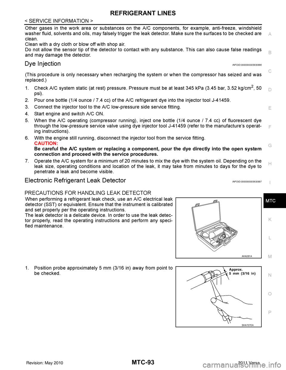
PRECAUTIONS FOR HANDLING LEAK DETECTOR
When performing a refrigerant leak check, use an A/C electrical leak
detector (SST) or equivalent. Ensure that the instrument is calibrated
and set properly per the operating instructions.
The leak detector is a delicate device. In order to use the leak detec-
tor properly, read the operating instructions and perform any speci-
fied maintenance.
1. Position probe approximately 5 mm (3/16 in) away from point to
be checked.
AHA281A
SHA707EA
Revision: May 2010 2011 Versa
Page 3464 of 3787

PG-44
< SERVICE INFORMATION >
HARNESS
Refer to "ENGINE ROOM HARNESS (LH VIEW)" for continuation of engine room harness.
G2 E1 GR/5 : Front wiper motor F2 E33 B/26 : ABS actuator and electric unit (control unit)
C3 E2 B/2 : Front and rear washer motor E2 E37 B/5 : Daytime light relay 1
F5 E4 Y/2 : Crash zone sensor D2 E38 L/5 : Daytime light relay 2
E4 E17 B/3 : Refrigerant pressure sensor E2 E41 — : Ground (ABS)
D2 E24 — : Engine ground C3 E50 W/2 : Washer fluid level switch
C3 E26 B/3 : Front combination lamp RH D1 E52 B/2 : Front wheel sensor RH
C4 E28 B/2 : Front fog lamp RH D2 E54 B/2 : Front combination lamp RH
D3 E30 B/2 : Front combination lamp RH
Revision: May 2010 2011 Versa