2011 NISSAN TIIDA Eco Switch
[x] Cancel search: Eco SwitchPage 59 of 3787

AT-42
< SERVICE INFORMATION >
TROUBLE DIAGNOSIS
TROUBLE DIAGNOSIS
DTC Inspection Priority ChartINFOID:0000000005928089
If some DTCs are displayed at the same time, perform inspections one by one based on the following priority
chart.
NOTE:
If DTC “CAN COMM CIRCUIT” is displayed with other DTCs, first perform the trouble diagnosis for
DTC “CAN COMM CIRCUIT”. Refer to AT- 8 7
.
Fail-SafeINFOID:0000000005928090
The TCM has an electronic Fail-safe mode. This allows t he vehicle to be driven even if a major electrical input/
output device circuit is damaged.
Under Fail-Safe, the vehicle always runs in 3GR, even wit h a shift lever position of “1”, “2” or “D”. The cus-
tomer may complain of sluggish or poor acceleration.
Always follow the “ AT-43, "
How to Perform Trouble Diagnosis for Quick and Accurate Repair" ”.
The SELF-DIAGNOSIS results will be as follows:
• The first SELF-DIAGNOSIS will indicate damage to the vehicle speed signal or the output speed sensor.
• During the next SELF-DIAGNOSIS, performed after checking the sensor, no damages will be indicated.
FAIL-SAFE FUNCTION
The following fail-safe functions allow vehicles to be driven even when sensor, switch or solenoid malfunction
occurs.
Output Speed Sensor
Vehicle speed signal is input from combination meter.
Accelerator Pedal Position Signal and Throttle Position Signal
TCM controls the throttle opening angle to a predetermined fixed position to enable driving if a malfunctioning
signal is input to TCM.
Transmission Range Switch
When the multiple transmission range switch signals are input to TCM, the priority of selector lever position
becomes “D”, “N”, “R”, “2” and “1” in order by internal TCM determination.
The use of 4GR is inhibited until normal operation resumes. Because the hydraulic circuit of the control valve
is switched by manual valve according to the selector lever position, however, actual operating condition of
vehicle becomes as follows.
Shift Solenoid Valve A and B
If non-standard solenoid signal is sent to TCM, use of certain gears is limited. Refer to chart shown below.
Priority Detected items
1 CAN communication line
2 Except above
Actual lever positionTransmission range switch input signal Running status
“P” “P” position and other position signals P
“R” “R” position and other position signals R
“N” “N” position and other position signals N
“D” “D” position and other position signals D
1 ⇔ D2 ⇔ D3 ⇔ D4
“2” “2” position and other position signals (Except “1” position)
21 ⇔ 22 ⇔ 23
“2” position and “1” position signals 21 ⇔ 22
“1” “1” position and other position signals (Except “2” position)
11 ⇔ 12 ⇔ 13
“1” position and “2” position signals 11 ⇔ 12
Revision: May 2010 2011 Versa
Page 73 of 3787
AT-56
< SERVICE INFORMATION >
TROUBLE DIAGNOSIS
• Before road test, familiarize yourself with all test procedures anditems to check.
• Test all inspection items until the symptom is uncovered. Include
NG items in “Diagnostic Wo rksheet Chart”(Refer to AT- 4 3
). Per-
form a diagnosis of the NG items after the completion of all the
road tests.
Check Before Engine Is StartedINFOID:0000000005928096
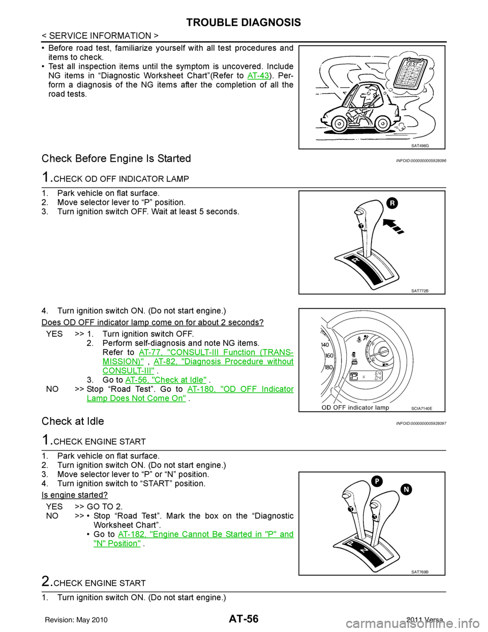
1.CHECK OD OFF INDICATOR LAMP
1. Park vehicle on flat surface.
2. Move selector lever to “P” position.
3. Turn ignition switch OFF. Wait at least 5 seconds.
4. Turn ignition switch ON. (Do not start engine.)
Does OD OFF indicator lamp come on for about 2 seconds?
YES >> 1. Turn ignition switch OFF. 2. Perform self-diagnosis and note NG items.Refer to AT-77, "
CONSULT-III Function (TRANS-
MISSION)" , AT-82, "Diagnosis Procedure without
CONSULT-III" .
3. Go to AT-56, "
Check at Idle" .
NO >> Stop “Road Test”. Go to AT-180, "
OD OFF Indicator
Lamp Does Not Come On" .
Check at IdleINFOID:0000000005928097
1.CHECK ENGINE START
1. Park vehicle on flat surface.
2. Turn ignition switch ON. (Do not start engine.)
3. Move selector lever to “P” or “N” position.
4. Turn ignition switch to “START” position.
Is engine started?
YES >> GO TO 2.
NO >> • Stop “Road Test”. Mark the box on the “Diagnostic Worksheet Chart”.
•Go to AT-182, "
Engine Cannot Be Started in "P" and
"N" Position" .
2.CHECK ENGINE START
1. Turn ignition switch ON. (Do not start engine.)
SAT496G
SAT772B
SCIA7140E
SAT769B
Revision: May 2010 2011 Versa
Page 96 of 3787
TROUBLE DIAGNOSISAT-79
< SERVICE INFORMATION >
DE
F
G H
I
J
K L
M A
B
AT
N
O P
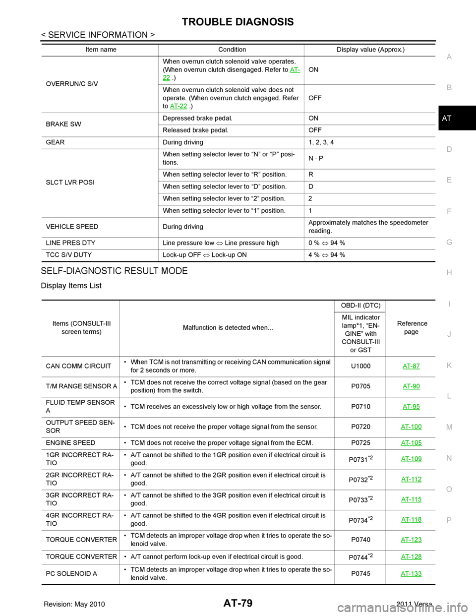
SELF-DIAGNOSTIC RESULT MODE
Display Items List
OVERRUN/C S/V When overrun clutch solenoid valve operates.
(When overrun clutch disengaged. Refer to
AT-22 .) ON
When overrun clutch solenoid valve does not
operate. (When overrun clutch engaged. Refer
to AT- 2 2
.) OFF
BRAKE SW Depressed brake pedal.
ON
Released brake pedal. OFF
GEAR During driving 1, 2, 3, 4
SLCT LVR POSI When setting selector lever to “N” or “P” posi-
tions.
N · P
When setting selector lever to “R” position. R
When setting selector lever to “D” position. D
When setting selector lever to “2” position. 2
When setting selector lever to “1” position. 1
VEHICLE SPEED During driving Approximately matches the speedometer
reading.
LINE PRES DTY Line pressure low ⇔ Line pressure high 0 % ⇔ 94 %
TCC S/V DUTY Lock-up OFF ⇔ Lock-up ON 4 % ⇔ 94 %
Item name
Condition Display value (Approx.)
Items (CONSULT-III
screen terms) Malfunction is detected when... OBD-II (DTC)
Reference page
MIL indicator
lamp*1, “EN-
GINE” with
CONSULT-III
or GST
CAN COMM CIRCUIT • When TCM is not transmitting or receiving CAN communication signal
for 2 seconds or more. U1000
AT- 8 7
T/M RANGE SENSOR A • TCM does not receive the correct voltage signal (based on the gear
position) from the switch. P0705
AT- 9 0
FLUID TEMP SENSOR
A • TCM receives an excessively low or high voltage from the sensor. P0710
AT- 9 5
OUTPUT SPEED SEN-
SOR• TCM does not receive the proper voltage signal from the sensor.
P0720AT- 1 0 0
ENGINE SPEED • TCM does not re ceive the proper voltage signal from the ECM. P0725AT- 1 0 5
1GR INCORRECT RA-
TIO • A/T cannot be shifted to the 1GR position even if electrical circuit is
good. P0731*2AT- 1 0 9
2GR INCORRECT RA-
TIO• A/T cannot be shifted to the 2GR position even if electrical circuit is
good. P0732*2AT- 11 2
3GR INCORRECT RA-
TIO• A/T cannot be shifted to the 3GR position even if electrical circuit is
good. P0733*2AT- 11 5
4GR INCORRECT RA-
TIO• A/T cannot be shifted to the 4GR position even if electrical circuit is
good. P0734*2AT- 11 8
TORQUE CONVERTER• TCM detects an improper voltage drop when it tries to operate the so-
lenoid valve. P0740
AT- 1 2 3
TORQUE CONVERTER • A/T cannot perform lock-up even if electrical circuit is good.
P0744*2AT- 1 2 8
PC SOLENOID A• TCM detects an improper voltage drop when it tries to operate the so-
lenoid valve. P0745
AT- 1 3 3
Revision: May 2010 2011 Versa
Page 98 of 3787

TROUBLE DIAGNOSISAT-81
< SERVICE INFORMATION >
DE
F
G H
I
J
K L
M A
B
AT
N
O P
CAN DIAGNOSTIC SUPPORT MONITOR MODE
Refer to LAN-14, "CAN Diagnostic Support Monitor".
DTC & SRT CONFIRMATION
Display Items List
2 POSITION SW (ON/OFF) X—
1 POSITION SW (ON/OFF) X—
ASCD-CRUISE (ON/OFF) X—
Signal input with CAN communication.
ASCD-OD CUT (ON/OFF) X—
KICKDOWN SW (ON/OFF) X—
Not mounted but displayed.
POWERSHIFT SW (ON/OFF) X—
CLOSED THL/SW (ON/OFF) X—
Signal input with CAN communication.
W/O THRL/P-SW (ON/OFF) X—
*SHIFT S/V A (ON/OFF) ——
Displays status of check signal (reinput
signal) for TCM control signal output. Re-
mains unchanged when solenoid valves
are open or shorted.
*SHIFT S/V B (ON/OFF)
——
*OVRRUN/C S/V (ON/OFF) ——
HOLD SW (ON/OFF) X— Not mounted but displayed.
BRAKE SW (ON/OFF) X— Stop lamp switch (Signal input with CAN
communication)
GEAR —X Gear position recognized by the TCM up-
dated after gear-shifting
SLCT LVR POSI —X Selector lever position is recognized by
the TCM.
For fail-safe operation, the specific value
used for control is displayed.
VEHICLE SPEED (km/h) —X Vehicle speed reco gnized by the TCM.
THROTTLE POSI (0.0/8) —X Degree of opening for accelerator recog-
nized by the TCM
For fail-safe operation, the specific value
used for control is displayed.
LINE PRES DTY (%) —X
TCC S/V DUTY (%) —X
SHIFT S/V A (ON/OFF) —X
SHIFT S/V B (ON/OFF) —X
OVERRUN/C S/V (ON/OFF) —X
SELF-D DP LMP (ON/OFF) —X
TC SLIP RATIO (0.000) ——
TC SLIP SPEED (rpm) —— Difference between engine speed and
torque converter input shaft speed
Monitored item (Unit)
Monitor Item Selection
Remarks
TCM INPUT
SIGNALS MAIN SIG-
NALS SELEC-
TION FROM
MENU
Revision: May 2010 2011 Versa
Page 99 of 3787
AT-82
< SERVICE INFORMATION >
TROUBLE DIAGNOSIS
Diagnosis Procedure without CONSULT-III
INFOID:0000000005928106
TCM SELF-DIAGNOSTIC PROCEDURE
Description
If a malfunction occurs in electrical system, turning ignition switch ON will illuminate OD OFF indicator lamp for
2 seconds. To detect a malfunction, entering a self-diagnosis start signal retrieves information on malfunctions
from memory and indicates malfunction by blinking OD OFF indicator lamp.
Diagnostic Procedure
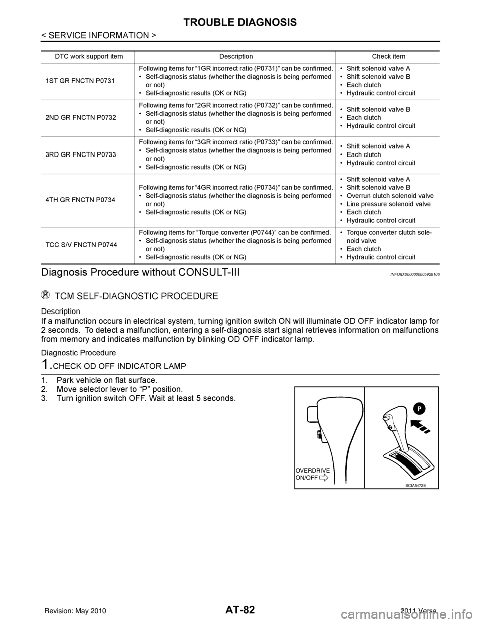
1.CHECK OD OFF INDICATOR LAMP
1. Park vehicle on flat surface.
2. Move selector lever to “P” position.
3. Turn ignition switch OFF. Wait at least 5 seconds.
DTC work support item Description Check item
1ST GR FNCTN P0731 Following items for “1GR incorrect ratio (P0731)” can be confirmed.
• Self-diagnosis status (whether the diagnosis is being performed
or not)
• Self-diagnostic results (OK or NG) • Shift solenoid valve A
• Shift solenoid valve B
• Each clutch
•Hydraulic co
ntrol circuit
2ND GR FNCTN P0732 Following items for “2GR incorrect ratio (P0732)” can be confirmed.
• Self-diagnosis status (whether the diagnosis is being performed
or not)
• Self-diagnostic results (OK or NG) • Shift solenoid valve B
• Each clutch
•Hydraulic co
ntrol circuit
3RD GR FNCTN P0733 Following items for “3GR incorrect ratio (P0733)” can be confirmed.
• Self-diagnosis status (whether the diagnosis is being performed
or not)
• Self-diagnostic results (OK or NG) • Shift solenoid valve A
• Each clutch
•Hydraulic co
ntrol circuit
4TH GR FNCTN P0734 Following items for “4GR incorrect ratio (P0734)” can be confirmed.
• Self-diagnosis status (whether the diagnosis is being performed
or not)
• Self-diagnostic results (OK or NG) • Shift solenoid valve A
• Shift solenoid valve B
• Overrun clutch solenoid valve
• Line pressure solenoid valve
• Each clutch
•Hydraulic co
ntrol circuit
TCC S/V FNCTN P0744 Following items for “Torque converter (P0744)” can be confirmed.
• Self-diagnosis status (whether the diagnosis is being performed
or not)
• Self-diagnostic results (OK or NG) • Torque converter clutch sole-
noid valve
• Each clutch
•Hydraulic co ntrol circuit
SCIA5472E
Revision: May 2010 2011 Versa
Page 100 of 3787

TROUBLE DIAGNOSISAT-83
< SERVICE INFORMATION >
DE
F
G H
I
J
K L
M A
B
AT
N
O P
4. Turn ignition switch ON. (Do not start engine.)
Does OD OFF indicator lamp come on about 2 seconds?
YES >> GO TO 2.
NO >> Stop procedure. Perform AT-180, "
OD OFF Indicator
Lamp Does Not Come On" before proceeding.
2.JUDGEMENT PROCEDURE STEP 1
1. Turn ignition switch OFF.
2. Keep pressing shift lock release button.
3. Move selector lever from “P” to “D” position.
4. Turn ignition switch ON. (Do not start engine.)
5. Keep pressing overdrive control switch while OD OFF indicator lamp is lighting up for 2 seconds. (OD OFF indicator lamp is on.)
6. Keep pressing overdrive control swit ch and shift selector lever to the “2” position. (OD OFF indicator lamp
is on.)
7. Stop pressing overdrive control switch. (OD OFF indicator lamp is on.)
8. Shift selector lever to the “1” position. (OD OFF indicator lamp is on.)
9. Keep pressing overdrive control switch . (OD OFF indicator lamp is off.)
10. Depress accelerator pedal fully while pressing overdrive control switch.
>> GO TO 3.
3.CHECK SELF-DIAGNOSIS CODE
Check OD OFF indicator lamp. Refer to "Judgement of Self-diagnosis Code" .
>>DIAGNOSIS END
Judgement of Self-diagnosis Code
SCIA7140E
Revision: May 2010 2011 Versa
Page 103 of 3787
AT-86
< SERVICE INFORMATION >
TROUBLE DIAGNOSIS
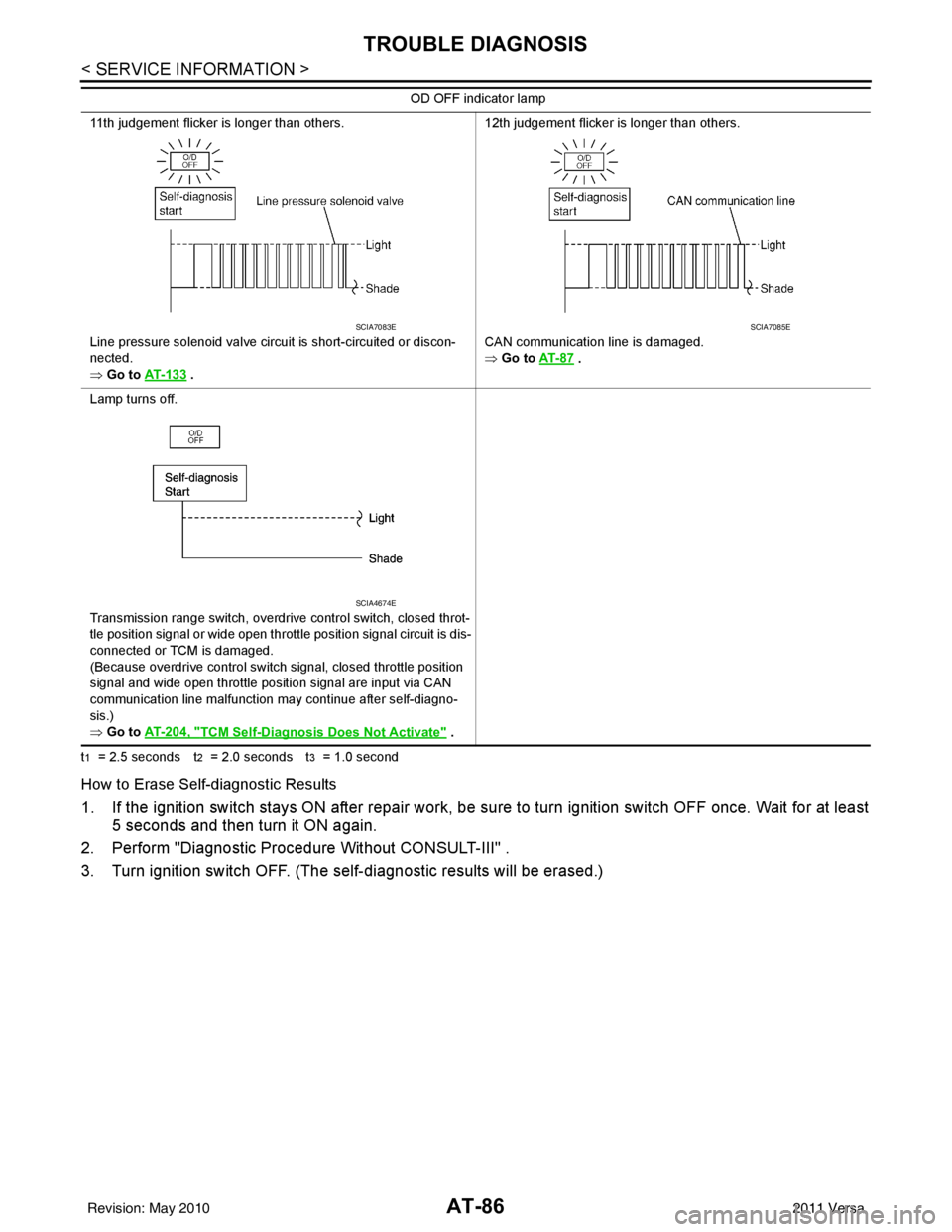
t1 = 2.5 seconds t2 = 2.0 seconds t3 = 1.0 second
How to Erase Self-diagnostic Results
1. If the ignition switch stays ON after repair work, be sure to turn ignition switch OFF once. Wait for at least
5 seconds and then turn it ON again.
2. Perform "Diagnostic Procedure Without CONSULT-III" .
3. Turn ignition switch OFF. (The se lf-diagnostic results will be erased.)
11th judgement flicker is longer than others.
Line pressure solenoid valve circuit is short-circuited or discon-
nected.
⇒ Go to AT- 1 3 3
. 12th judgement flicker is longer than others.
CAN communication line is damaged.
⇒ Go to
AT- 8 7
.
Lamp turns off.
Transmission range switch, overdrive control switch, closed throt-
tle position signal or wide open throttle position signal circuit is dis-
connected or TCM is damaged.
(Because overdrive control switch signal, closed throttle position
signal and wide open throttle position signal are input via CAN
communication line malfunction may continue after self-diagno-
sis.)
⇒ Go to AT- 2 0 4 , "
TCM Self-Diagnosis Does Not Activate" .
OD OFF indicator lamp
SCIA7083ESCIA7085E
SCIA4674E
Revision: May 2010
2011 Versa
Page 104 of 3787
U1000 CAN COMM CIRCUITAT-87
< SERVICE INFORMATION >
DE
F
G H
I
J
K L
M A
B
AT
N
O P
U1000 CAN COMM CIRCUIT
DescriptionINFOID:0000000005928107
CAN (Controller Area Network) is a serial communication line for real time application. It is an on-vehicle mul-
tiplex communication line with high data communica tion speed and excellent malfunction detection ability.
Many electronic control units are equipped onto a vehicle, and each control unit shares information and links
with other control units during operation (not independent). In CAN communication, control units are con-
nected with 2 communication lines (CAN H line, CAN L li ne) allowing a high rate of information transmission
with less wiring. Each control unit transmits/recei ves data but selectively reads required data only.
On Board Diagnosis LogicINFOID:0000000005928108
• This is an OBD-II self-diagnostic item.
• Diagnostic trouble code “U1000 CAN COMM CIRCUIT” wit h CONSULT-III or 12th judgement flicker without
CONSULT-III is detected when TCM cannot communicate to other control units.
Possible CauseINFOID:0000000005928109
Harness or connector
(CAN communication line is open or shorted.)
DTC Confirmation ProcedureINFOID:0000000005928110
CAUTION:
If performing this “DTC Confirmation Procedure” again, always turn ignition switch OFF and wait at
least 10 seconds before continuing.
After the repair, perform the following procedure to confirm the malfunction is eliminated.
WITH CONSULT-III
1. Turn ignition switch ON.
2. Select “DATA MONITOR” mode for “TRANSMISSION” with CONSULT-III.
3. Touch “START”.
4. Wait at least 6 seconds or start engine and wait for at least 6 seconds.
5. If DTC is detected, go to AT-89, "
Diagnosis Procedure".
WITH GST
Follow the procedure “WITH CONSULT-III”.
WITHOUT CONSULT-III
1. Turn ignition switch ON.
2. Wait at least 6 seconds or start engine and wait at least 6 seconds.
3. Perform self-diagnosis. Refer to AT-82, "
Diagnosis Procedure without CONSULT-III".
4. If DTC is detected, go to AT-89, "
Diagnosis Procedure".
Revision: May 2010 2011 Versa