2011 NISSAN TIIDA filter
[x] Cancel search: filterPage 2668 of 3787

FL-1
ENGINE
C
DE
F
G H
I
J
K L
M
SECTION FL
A
FL
N
O P
CONTENTS
FUEL SYSTEM
SERVICE INFORMATION .. ..........................2
PRECAUTIONS .............................................. .....2
Precaution for Supplemental Restraint System
(SRS) "AIR BAG" and "SEAT BELT PRE-TEN-
SIONER" ............................................................. ......
2
Precaution Necessary for Steering Wheel Rota-
tion After Battery Disconnect ............................... ......
2
PREPARATION ...................................................4
Special Service Tool ........................................... ......4
Commercial Service Tool ..........................................4
FUEL SYSTEM ....................................................5
Checking Fuel Line ............................................. ......5
General Precaution ...................................................5
FUEL LEVEL SENSOR UNIT, FUEL FILTER
AND FUEL PUMP ASSEMBLY .........................
6
Component .......................................................... .....6
Removal and Installation ..........................................6
FUEL TANK ......................................................10
Component .......................................................... ....10
Removal and Installation .........................................10
EVAPORATIVE EMISSION SYSTEM ...............15
Exploded View .........................................................15
Removal and Installation (HR16DE) ........................15
Exploded View .........................................................16
Removal and Installation (MR18DE) .......................16
SERVICE DATA AND SPECIFICATIONS
(SDS) .................................................................
18
Standard and Limit .............................................. ....18
Revision: May 2010 2011 Versa
Page 2673 of 3787
FL-6
< SERVICE INFORMATION >
FUEL LEVEL SENSOR UNIT, FUEL FILTER AND FUEL PUMP ASSEMBLY
FUEL LEVEL SENSOR UNIT, FUEL FILTER AND FUEL PUMP ASSEMBLY
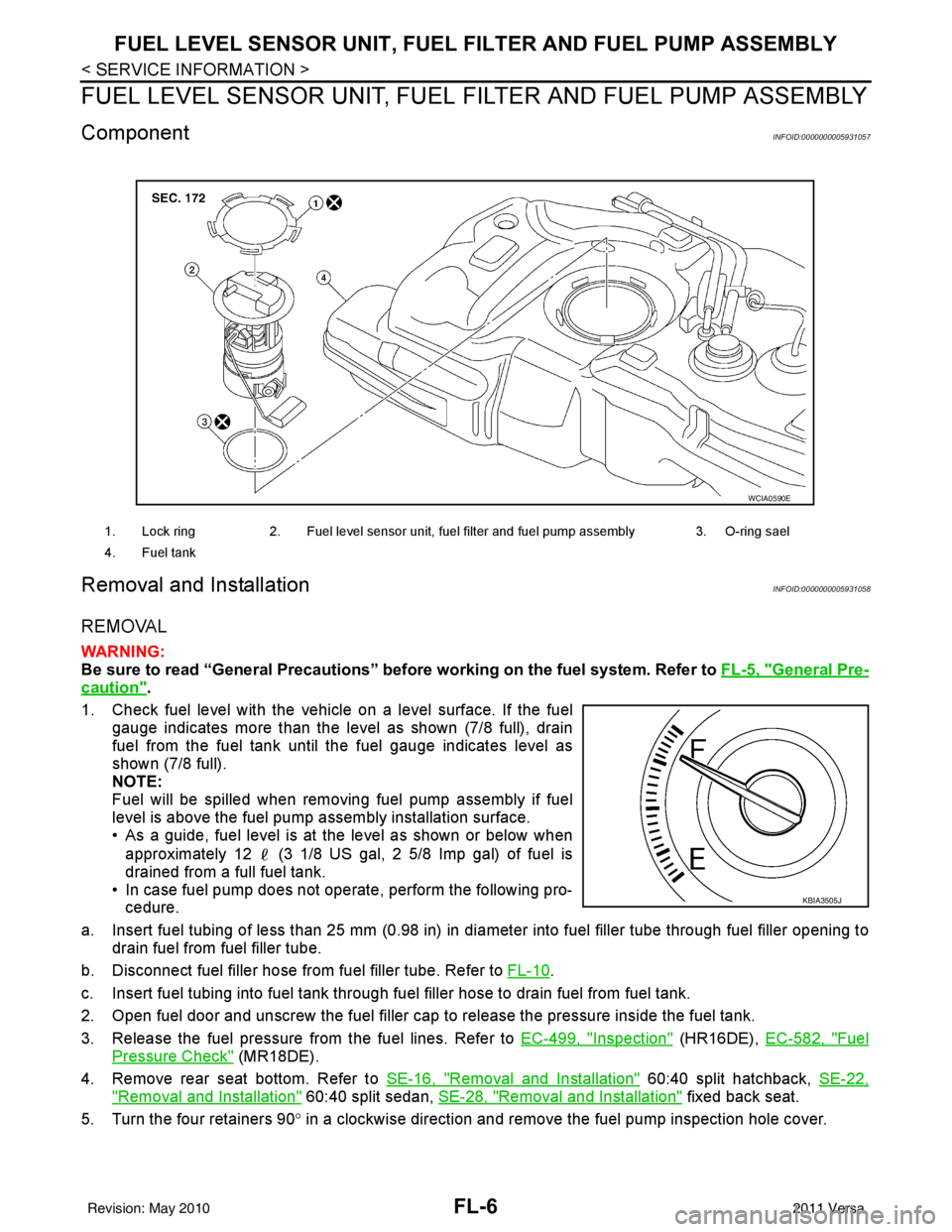
ComponentINFOID:0000000005931057
Removal and InstallationINFOID:0000000005931058
REMOVAL
WARNING:
Be sure to read “General Precautions” be fore working on the fuel system. Refer to FL-5, "
General Pre-
caution".
1. Check fuel level with the vehicle on a level surface. If the fuel gauge indicates more than the level as shown (7/8 full), drain
fuel from the fuel tank until the fuel gauge indicates level as
shown (7/8 full).
NOTE:
Fuel will be spilled when removing fuel pump assembly if fuel
level is above the fuel pump assembly installation surface.
• As a guide, fuel level is at the level as shown or below when
approximately 12 (3 1/8 US gal, 2 5/8 Imp gal) of fuel is
drained from a full fuel tank.
• In case fuel pump does not operate, perform the following pro- cedure.
a. Insert fuel tubing of less than 25 mm (0.98 in) in di ameter into fuel filler tube through fuel filler opening to
drain fuel from fuel filler tube.
b. Disconnect fuel filler hose from fuel filler tube. Refer to FL-10
.
c. Insert fuel tubing into fuel tank through f uel filler hose to drain fuel from fuel tank.
2. Open fuel door and unscrew the fuel filler cap to release the pressure inside the fuel tank.
3. Release the fuel pressure from the fuel lines. Refer to EC-499, "
Inspection" (HR16DE), EC-582, "Fuel
Pressure Check" (MR18DE).
4. Remove rear seat bottom. Refer to SE-16, "
Removal and Installation" 60:40 split hatchback, SE-22,
"Removal and Installation" 60:40 split sedan, SE-28, "Removal and Installation" fixed back seat.
5. Turn the four retainers 90 ° in a clockwise direction and remove the fuel pump inspection hole cover.
1. Lock ring 2. Fuel level sensor unit, fuel filter and fuel pump assembly 3. O-ring sael
4. Fuel tank
WCIA0590E
KBIA3505J
Revision: May 2010 2011 Versa
Page 2674 of 3787
FUEL LEVEL SENSOR UNIT, FUEL FILTER AND FUEL PUMP ASSEMBLYFL-7
< SERVICE INFORMATION >
C
DE
F
G H
I
J
K L
M A
FL
NP
O
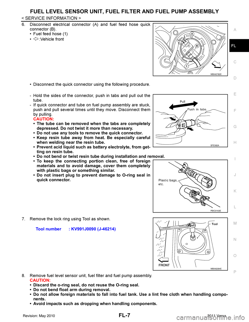
6. Disconnect electrical connector (A) and fuel feed hose quick
connector (B).
• Fuel feed hose (1)
• :Vehicle front
• Disconnect the quick connector using the following procedure.
- Hold the sides of the connector, push in tabs and pull out thetube.
- If quick connector and tube on fuel pump assembly are stuck, push and pull several times until they move. Disconnect them
by pulling.
CAUTION:
• The tube can be removed when the tabs are completely
depressed. Do not twist it more than necessary.
• Do not use any tools to remove the quick connector.
• Keep resin tube away from heat. Be especially careful
when welding near the resin tube.
• Prevent acid liquid such as battery electrolyte, from get- ting on resin tube.
• Do not bend or twist resin tube during installation and removal.
• To keep the connecting port ion clean, free of foreign
materials and to avoid damage, cover them completely
with plastic bags or something similar.
• Do not insert plug to prevent damage to O-ring seal in quick connector.
7. Remove the lock ring using Tool as shown.
8. Remove fuel level sensor unit, fuel filter and fuel pump assembly. CAUTION:
• Discard the o-ring seal, do not reuse the O-ring seal.
• Do not bend float arm during removal.
• Do not allow foreign materials to fall into fuel tank. Use a lint free cloth when handling compo-
nents.
• Avoid impacts such as droppin g when handling components.
WBIA0782E
SFE562A
PBIC0163E
Tool number : KV991J0090 (J-46214)
WBIA0284E
Revision: May 2010 2011 Versa
Page 2675 of 3787
FL-8
< SERVICE INFORMATION >
FUEL LEVEL SENSOR UNIT, FUEL FILTER AND FUEL PUMP ASSEMBLY
INSPECTION AFTER REMOVAL
Make sure that the fuel level sensor unit, fuel filter and fuel pump is free from defects and foreign materials.
INSTALLATION
Installation is in the reverse order of removal.
Fuel Level Sensor Unit, Fuel Filter and Fuel Pump Assembly
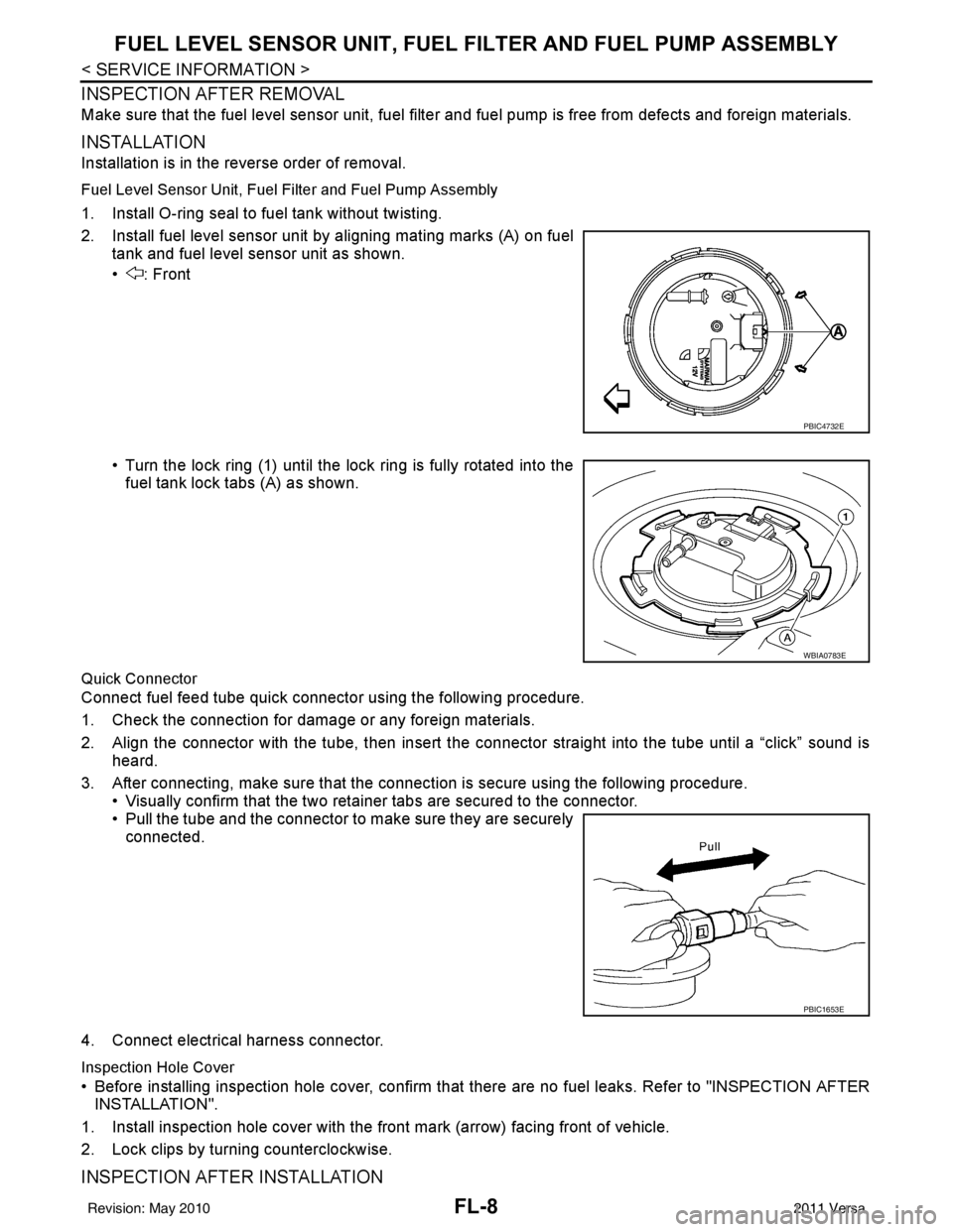
1. Install O-ring seal to fuel tank without twisting.
2. Install fuel level sensor unit by aligning mating marks (A) on fuel
tank and fuel level sensor unit as shown.
• : Front
• Turn the lock ring (1) until the lock ring is fully rotated into thefuel tank lock tabs (A) as shown.
Quick Connector
Connect fuel feed tube quick connector using the following procedure.
1. Check the connection for damage or any foreign materials.
2. Align the connector with the tube, then insert the connector straight into the tube until a “click” sound is heard.
3. After connecting, make sure that the connec tion is secure using the following procedure.
• Visually confirm that the two retainer tabs are secured to the connector.
• Pull the tube and the connector to make sure they are securely connected.
4. Connect electrical harness connector.
Inspection Hole Cover
• Before installing inspection hole cover, confirm that there are no fuel leaks. Refer to "INSPECTION AFTER
INSTALLATION".
1. Install inspection hole cover with the front mark (arrow) facing front of vehicle.
2. Lock clips by turning counterclockwise.
INSPECTION AFTER INSTALLATION
PBIC4732E
WBIA0783E
PBIC1653E
Revision: May 2010 2011 Versa
Page 2676 of 3787

FUEL LEVEL SENSOR UNIT, FUEL FILTER AND FUEL PUMP ASSEMBLYFL-9
< SERVICE INFORMATION >
C
DE
F
G H
I
J
K L
M A
FL
NP
O
Use the following procedure to check for fuel leaks.
1. Turn ignition switch “ON” (without starting the engi
ne), to check the connections for fuel leaks with the
electric fuel pump applying pressure to the fuel piping.
2. Start the engine and let it idle to check that ther e are no fuel leaks at the fuel system connections.
Revision: May 2010 2011 Versa
Page 2854 of 3787
![NISSAN TIIDA 2011 Service Repair Manual LAN-8
< SERVICE INFORMATION >[CAN FUNDAMENTAL]
CAN COMMUNICATION SYSTEM
CAN Communication Control Circuit
INFOID:0000000005928516
*: These are the only control units wired with both ends of CAN commun](/manual-img/5/57396/w960_57396-2853.png "NISSAN TIIDA 2011 Service Repair Manual LAN-8
< SERVICE INFORMATION >[CAN FUNDAMENTAL]
CAN COMMUNICATION SYSTEM
CAN Communication Control Circuit
INFOID:0000000005928516
*: These are the only control units wired with both ends of CAN commun")
LAN-8
< SERVICE INFORMATION >[CAN FUNDAMENTAL]
CAN COMMUNICATION SYSTEM
CAN Communication Control Circuit
INFOID:0000000005928516
*: These are the only control units wired with both ends of CAN communication system.
SKIB8713E
Component System description
CAN controller It controls CAN communication signal transmission and reception, error detection, etc.
Transceiver IC It converts digital signal into CAN communication signal, and CAN communication signal into digital
signal.
Noise filter It eliminates noise of CAN communication signal.
Termination circuit
*
(Resistance of approx. 120 Ω) It produces potential difference.
Revision: May 2010
2011 Versa
Page 3149 of 3787

LU-1
ENGINE
C
DE
F
G H
I
J
K L
M
SECTION LU
A
LU
N
O P
CONTENTS
ENGINE LUBRICATION SYSTEM
HR16DE
PRECAUTION ....... ........................................
2
PRECAUTIONS .............................................. .....2
Precaution for Supplemental Restraint System
(SRS) "AIR BAG" and "SEAT BELT PRE-TEN-
SIONER" ............................................................. ......
2
Precaution for Liquid Gasket .....................................2
PREPARATION ............................................4
PREPARATION .............................................. .....4
Special Service Tool ........................................... ......4
Commercial Service Tool ..........................................4
FUNCTION DIAGNOSIS ...............................6
DESCRIPTION ............................................... .....6
Engine Lubrication System ................................. ......6
Engine Lubrication System Schematic ......................6
ON-VEHICLE MAINTENANCE .....................7
ENGINE OIL ................................................... .....7
Inspection ............................................................ ......7
Draining .....................................................................8
Refilling .....................................................................8
OIL FILTER .........................................................9
Removal and Installation ...........................................9
ON-VEHICLE REPAIR .... .............................10
OIL PUMP ....................................................... ....10
Removal and Installation .........................................10
SERVICE DATA AND SPECIFICATIONS
(SDS) ......... ................................. ..................
11
SERVICE DATA AND SPECIFICATIONS
(SDS) .................................................................
11
Engine Oil Capacity ............................................. ....11
Engine Oil Pressure .................................................11
MR18DE
SERVICE INFORMATION .. .........................
12
PRECAUTIONS .................................................12
Precaution for Supplemental Restraint System
(SRS) "AIR BAG" and "SEAT BELT PRE-TEN-
SIONER" ............................................................. ....
12
Precaution Necessary for Steering Wheel Rota-
tion After Battery Disconnect ...................................
12
Precaution for Liquid Gasket ...................................13
PREPARATION .................................................14
Special Service Tool ................................................14
Commercial Service Tool ........................................14
LUBRICATION SYSTEM ..................................16
Lubrication Circuit ....................................................16
ENGINE OIL ......................................................17
Inspection ................................................................17
Changing Engine Oil ................................................18
OIL FILTER .......................................................20
Removal and Installation .........................................20
OIL PUMP .........................................................21
Component ..............................................................21
Removal and Installation .........................................21
SERVICE DATA AND SPECIFICATIONS
(SDS) .................................................................
23
Standard and Limit ..................................................23
Revision: May 2010 2011 Versa
Page 3152 of 3787
![NISSAN TIIDA 2011 Service Repair Manual LU-4
< PREPARATION >[HR16DE]
PREPARATION
PREPARATION
PREPARATION
Special Service ToolINFOID:0000000005928683
The actual shapes of Kent-Moore tool
s may differ from those of special service tools illus](/manual-img/5/57396/w960_57396-3151.png "NISSAN TIIDA 2011 Service Repair Manual LU-4
< PREPARATION >[HR16DE]
PREPARATION
PREPARATION
PREPARATION
Special Service ToolINFOID:0000000005928683
The actual shapes of Kent-Moore tool
s may differ from those of special service tools illus")
LU-4
< PREPARATION >[HR16DE]
PREPARATION
PREPARATION
PREPARATION
Special Service ToolINFOID:0000000005928683
The actual shapes of Kent-Moore tool
s may differ from those of special service tools illustrated here.
Commercial Service ToolINFOID:0000000005928684
Tool number
(Kent-Moore No.)
Tool name Description
ST25051001
(J-25695-1)
Oil pressure gauge Measuring oil pressure
Maximum measuring range: 2,452 kPa (25
kg/cm
2, 356 psi)
ST25052000
(J-25695-2)
Hose Adapting oil pressure gauge to cylinder block
KV10115801
(J-38956)
Oil filter wrench Removing oil filter
a: 64.3 mm (2.531 in)
WS39930000
(—)
Tube presser Pressing the tube of liquid gasket
NT050
S-NT559
S-NT375
NT052
Revision: May 2010
2011 Versa