Page 3202 of 3787
ENGINE MAINTENANCE (MR18DE)MA-31
< SERVICE INFORMATION >
C
DE
F
G H
I
J
K
M A
B
MA
N
O P
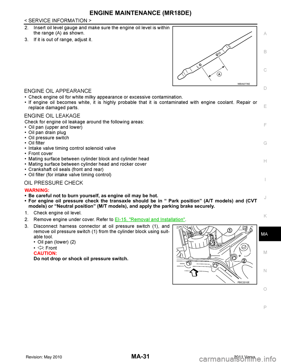
2. Insert oil level gauge and make sure the engine oil level is within the range (A) as shown.
3. If it is out of range, adjust it.
ENGINE OIL APPEARANCE
• Check engine oil for white milky appearance or excessive contamination.
• If engine oil becomes white, it is highly probable t hat it is contaminated with engine coolant. Repair or
replace damaged parts.
ENGINE OIL LEAKAGE
Check for engine oil leakage around the following areas:
• Oil pan (upper and lower)
• Oil pan drain plug
• Oil pressure switch
• Oil filter
• Intake valve timing control solenoid valve
• Front cover
• Mating surface between cylinder block and cylinder head
• Mating surface between cylinder head and rocker cover
• Crankshaft oil seals (front and rear)
• Oil filter (for intake valve timing control)
OIL PRESSURE CHECK
WARNING:
• Be careful not to burn yoursel f, as engine oil may be hot.
• For engine oil pressure check the transaxle should be in “ Park position” (A/T models) and (CVT
models) or “Neutral position” (M/T mode ls), and apply the parking brake securely.
1. Check engine oil level.
2. Remove engine under cover. Refer to EI-15, "
Removal and Installation".
3. Disconnect harness connector at oil pressure switch (1), and remove oil pressure switch (1) from the cylinder block using suit-
able tool.
• Oil pan (lower) (2)
• : Front
CAUTION:
Do not drop or shock oil pressure switch.
WBIA0776E
PBIC3310E
Revision: May 2010 2011 Versa
Page 3204 of 3787
ENGINE MAINTENANCE (MR18DE)MA-33
< SERVICE INFORMATION >
C
DE
F
G H
I
J
K
M A
B
MA
N
O P
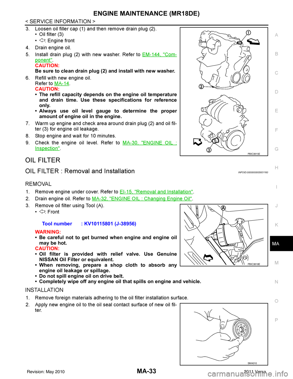
3. Loosen oil filler cap (1) and then remove drain plug (2). • Oil filter (3)
• : Engine front
4. Drain engine oil.
5. Install drain plug (2) with new washer. Refer to EM-144, "
Com-
ponent".
CAUTION:
Be sure to clean drain plug (2 ) and install with new washer.
6. Refill with new engine oil. Refer to MA-14
.
CAUTION:
• The refill capacity depends on the engine oil temperature
and drain time. Use these specifications for reference
only.
• Always use oil level gauge to determine the proper amount of engine oil in the engine.
7. Warm up engine and check area around drain plug (2) and oil fil- ter (3) for engine oil leakage.
8. Stop engine and wait for 10 minutes.
9. Check the engine oil level. Refer to MA-30, "
ENGINE OIL :
Inspection".
OIL FILTER
OIL FILTER : Removal and InstallationINFOID:0000000005931160
REMOVAL
1. Remove engine under cover. Refer to EI-15, "Removal and Installation".
2. Drain engine oil. Refer to MA-32, "
ENGINE OIL : Changing Engine Oil".
3. Remove oil filter using Tool (A). • : Front
WARNING:
• Be careful not to get burned when engine and engine oil
may be hot.
CAUTION:
• Oil filter is provided with relief valve. Use Genuine
NISSAN Oil Filter or equivalent.
• When removing, prepare a s hop cloth to absorb any
engine oil leakage or spillage.
• Do not spill engine oil on drive belt.
• Completely wipe off any engine oil that spills on engine and vehicle.
INSTALLATION
1. Remove foreign materials adhering to the oil filter installation surface.
2. Apply new engine oil to the oil seal contact surface of new oil fil-
ter.
PBIC3915E
Tool number : KV10115801 (J-38956)
PBIC3818E
SMA010
Revision: May 2010 2011 Versa
Page 3205 of 3787
MA-34
< SERVICE INFORMATION >
ENGINE MAINTENANCE (MR18DE)
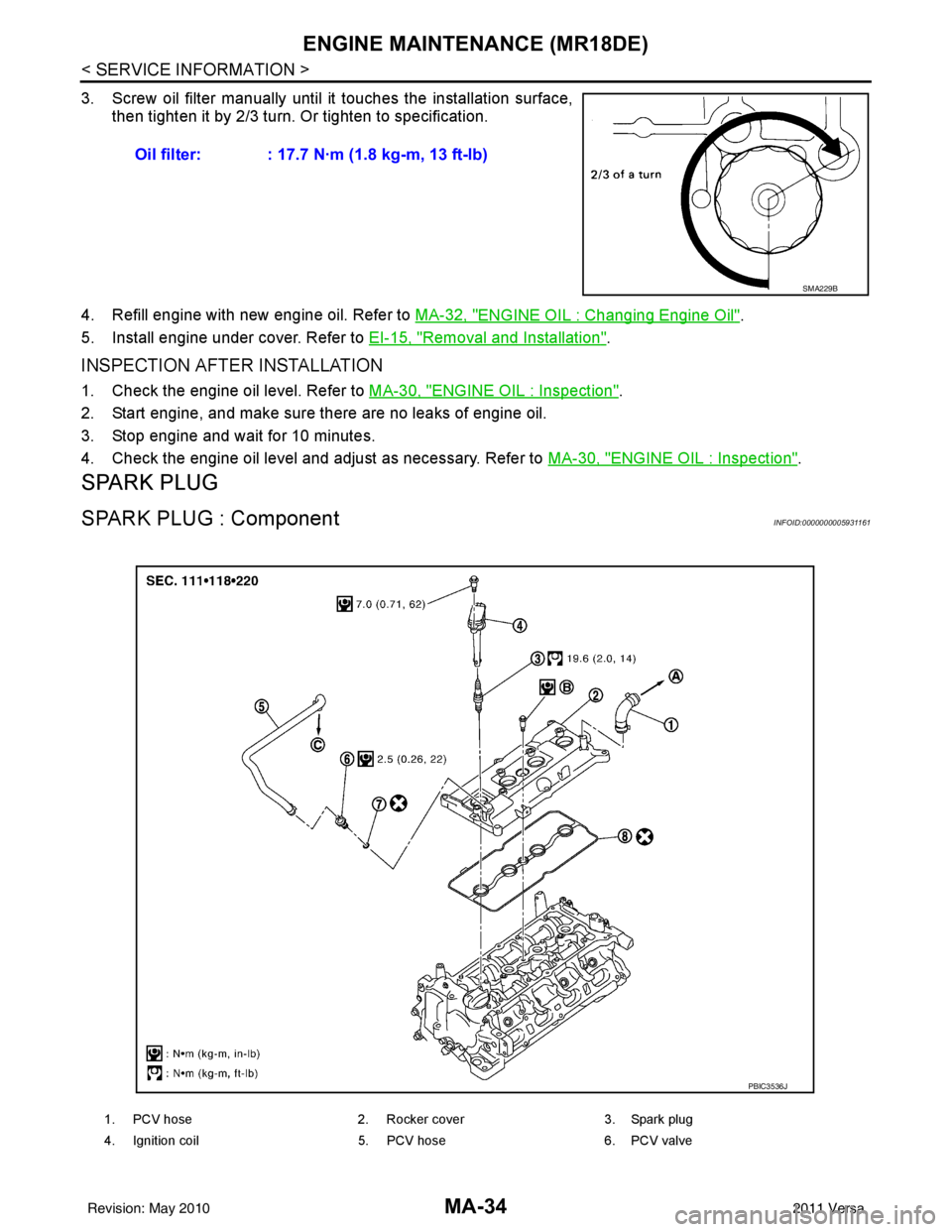
3. Screw oil filter manually until it touches the installation surface,
then tighten it by 2/3 turn. Or tighten to specification.
4. Refill engine with new engine oil. Refer to MA-32, "
ENGINE OIL : Changing Engine Oil".
5. Install engine under cover. Refer to EI-15, "
Removal and Installation".
INSPECTION AFTER INSTALLATION
1. Check the engine oil level. Refer to MA-30, "ENGINE OIL : Inspection".
2. Start engine, and make sure there are no leaks of engine oil.
3. Stop engine and wait for 10 minutes.
4. Check the engine oil level and adjust as necessary. Refer to MA-30, "
ENGINE OIL : Inspection".
SPARK PLUG
SPARK PLUG : ComponentINFOID:0000000005931161
Oil filter: : 17.7 N·m (1.8 kg-m, 13 ft-lb)
SMA229B
1. PCV hose2. Rocker cover3. Spark plug
4. Ignition coil 5. PCV hose6. PCV valve
PBIC3536J
Revision: May 2010 2011 Versa
Page 3377 of 3787
A/C UNIT ASSEMBLYMTC-61
< SERVICE INFORMATION >
C
DE
F
G H
I
K L
M A
B
MTC
N
O P
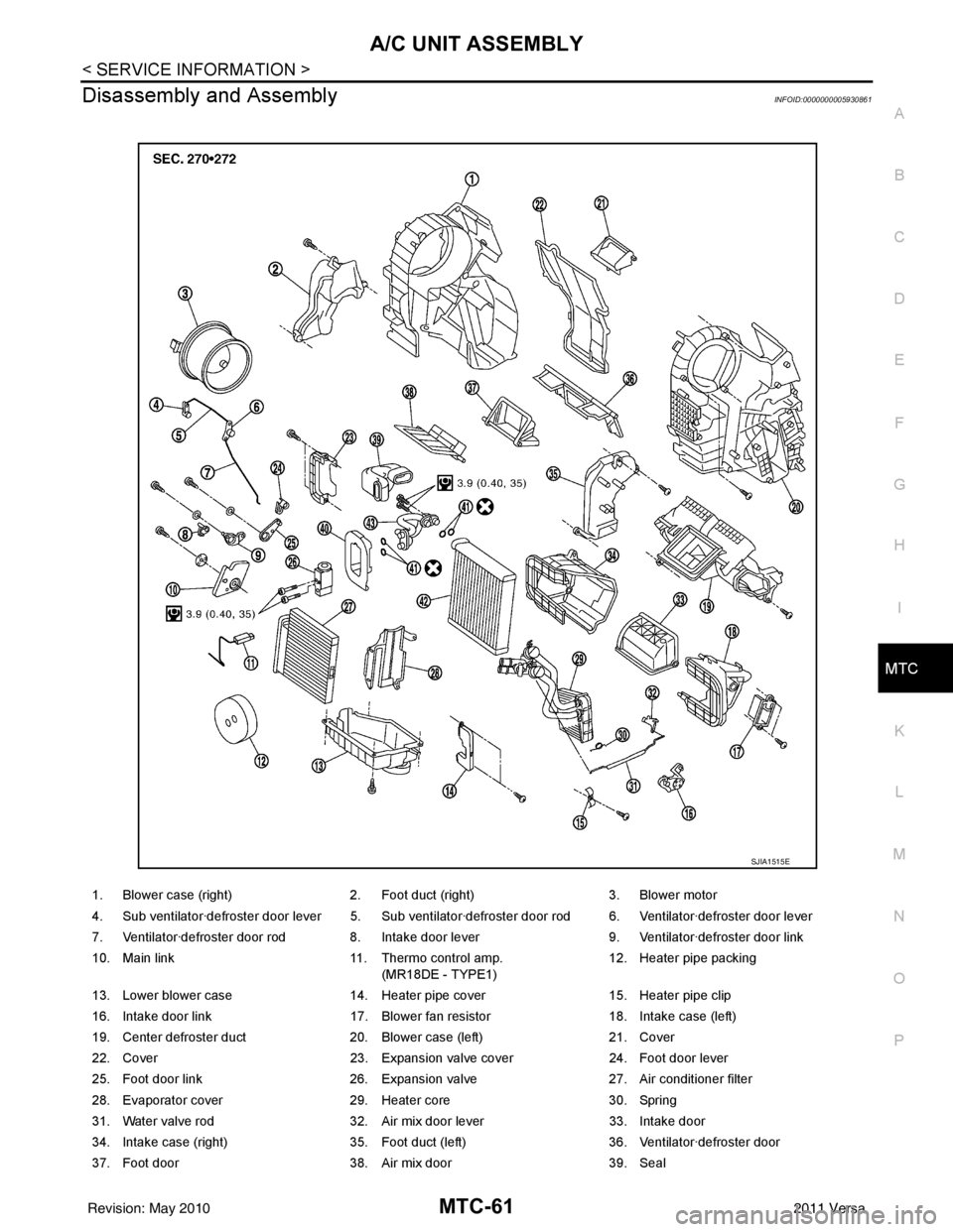
Disassembly and AssemblyINFOID:0000000005930861
1. Blower case (right) 2. Foot duct (right) 3. Blower motor
4. Sub ventilator·defroster door lever 5. Sub ventilator·defroster door rod 6. Ventilator·defroster door lever
7. Ventilator·defroster door rod 8. Intake door lever 9. Ventilator·defroster door link
10. Main link 11. Thermo control amp.
(MR18DE - TYPE1) 12. Heater pipe packing
13. Lower blower case 14. Heater pipe cover 15. Heater pipe clip
16. Intake door link 17. Blower fan resistor 18. Intake case (left)
19. Center defroster duct 20. Blower case (left) 21. Cover
22. Cover 23. Expansion valve cover 24. Foot door lever
25. Foot door link 26. Expansion valve 27. Air conditioner filter
28. Evaporator cover 29. Heater core 30. Spring
31. Water valve rod 32. Air mix door lever 33. Intake door
34. Intake case (right) 35. Foot duct (left) 36. Ventilator·defroster door
37. Foot door 38. Air mix door 39. Seal
SJIA1515E
Revision: May 2010 2011 Versa