2011 NISSAN TIIDA RON 91
[x] Cancel search: RON 91Page 524 of 3787

BL-14
< SERVICE INFORMATION >
HOOD
5. After adjustment tighten lock bolts to the specified torque.
6. Install the front grille. Refer to EI-23
.
Removal and InstallationINFOID:0000000005929277
HOOD ASSEMBLY
Removal
1. Remove hinge nuts on hood and remove hood assembly.
CAUTION:
Two technicians should be used to avoid damaging the
hood during removal.
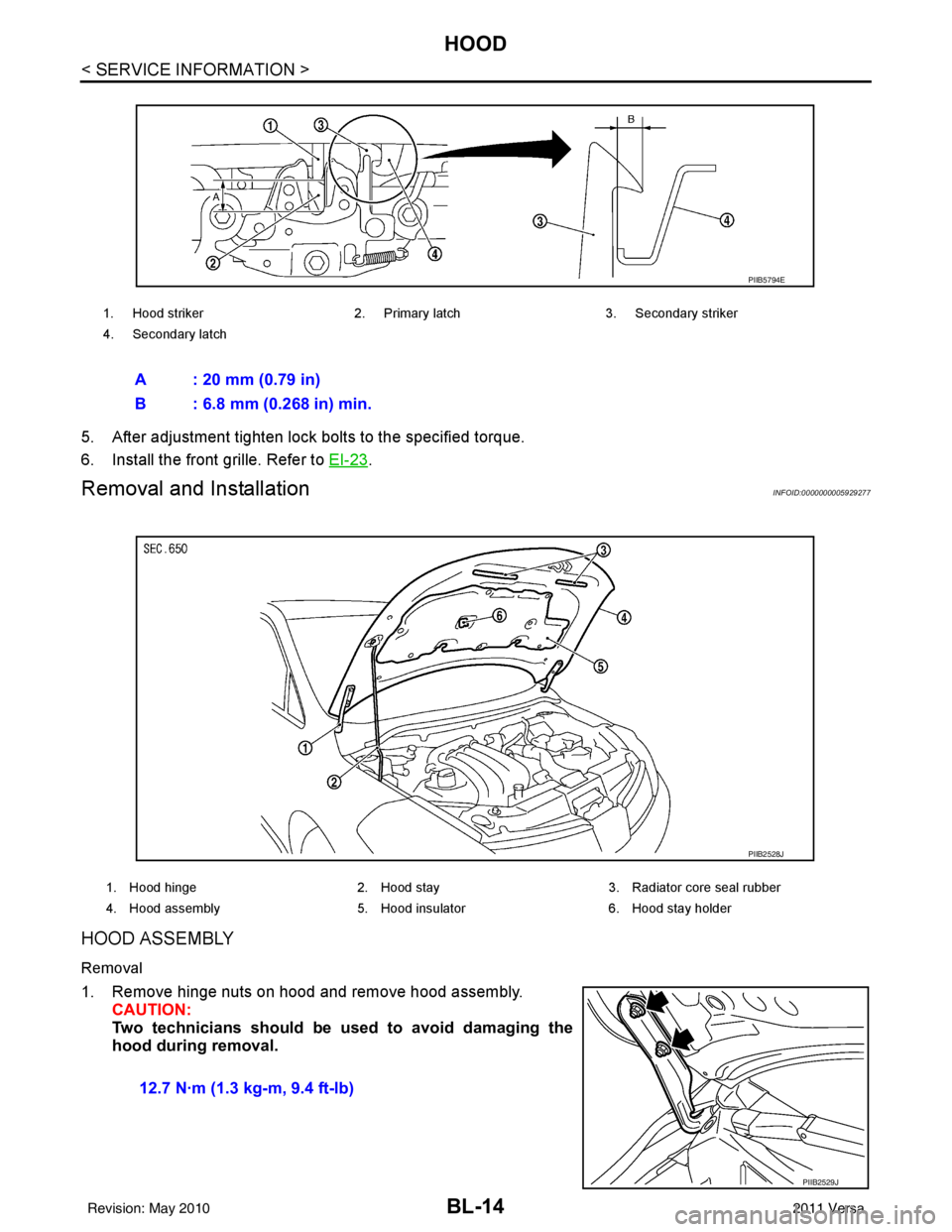
1. Hood striker 2. Primary latch 3. Secondary striker
4. Secondary latch
A : 20 mm (0.79 in)
B : 6.8 mm (0.268 in) min.
PIIB5794E
1. Hood hinge 2. Hood stay3. Radiator core seal rubber
4. Hood assembly 5. Hood insulator 6. Hood stay holder
PIIB2528J
12.7 N·m (1.3 kg-m, 9.4 ft-lb)
PIIB2529J
Revision: May 2010 2011 Versa
Page 525 of 3787

HOODBL-15
< SERVICE INFORMATION >
C
DE
F
G H
J
K L
M A
B
BL
N
O P
Installation
Installation is in the reverse order of removal.
CAUTION:
• Before installing hood hinge, apply anticorrosive
agent onto the surfaces that make contact with the
vehicle body.
• After installing, perform hood fitting adjustment. Refer to BL-13, "
Fitting Adjustment".
HOOD HINGE
Removal
1. Remove hood assembly. Refer to BL-14, "Removal and Installation".
2. Remove front fender. Refer to BL-21, "
Removal and Installation".
3. Remove bolts and the hood hinge.
Installation
Installation is in the reverse order of removal.
Removal and Installation of Hood Lock ControlINFOID:0000000005929278
REMOVAL
Hood Lock
1. Remove front grille (LH). Refer to EI-23, "Removal and Installation".
2. Remove hood lock bolts.
3. Remove hood lock from hood lock cable. 12.7 N·m (1.3 kg-m, 9.4 ft-lb)
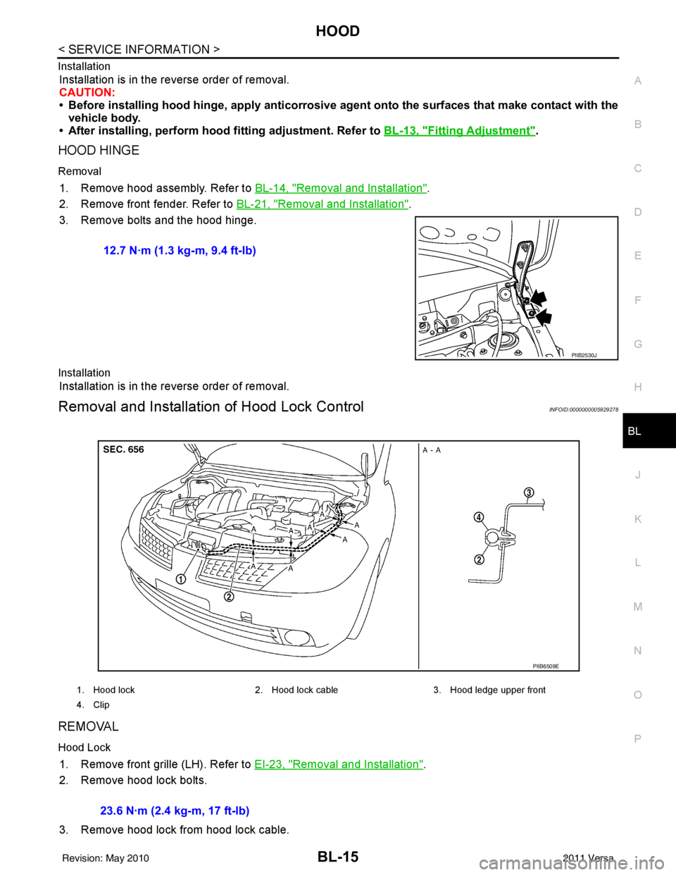
PIIB2530J
1. Hood lock
2. Hood lock cable 3. Hood ledge upper front
4. Clip
PIIB6509E
23.6 N·m (2.4 kg-m, 17 ft-lb)
Revision: May 2010 2011 Versa
Page 526 of 3787

BL-16
< SERVICE INFORMATION >
HOOD
Hood Lock Reinforcement
1. Remove front bumper. Refer to EI-15, "Removal and Installation".
2. Remove crash zone sensor. Refer to SRS-42, "
Removal and Installation".
3. Remove bolts, and the hood lock reinforcement.
Hood Lock Cable
1. Remove front grille (LH/RH). Refer to EI-23, "Removal and Installation".
2. Remove fender protector (LH). Refer to EI-26, "
Component".
3. Remove hood lock, and remove hood lock cable from hood lock.
4. Remove radiator core upper support, hood ledge, and then remove hood lock cable.
5. Remove hood opener on bottom left of instrument panel, and then remove hood lock cable.
6. Remove grommet on lower dashboard, and pull out hood lock cable from passenger room side.
CAUTION:
While pulling the cable, be car eful not to damage (peel)
hood opener cable outer surface on edges of body through
hole.
INSTALLATION
Installation is in the reverse order of removal.
• Perform hood fitting adjustment. Refer to BL-13, "
Fitting Adjustment".
Hood Lock Reinforcement
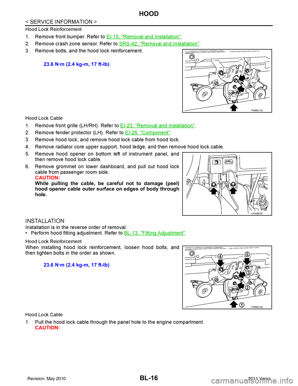
When installing hood lock reinforcement, loosen hood bolts, and
then tighten bolts in the order as shown.
Hood Lock Cable
1. Pull the hood lock cable through the panel hole to the engine compartment. CAUTION: 23.6 N·m (2.4 kg-m, 17 ft-lb)
PIIB6511E
LIIA2667E
23.6 N·m (2.4 kg-m, 17 ft-lb)
PIIB6513E
Revision: May 2010
2011 Versa
Page 527 of 3787

HOODBL-17
< SERVICE INFORMATION >
C
DE
F
G H
J
K L
M A
B
BL
N
O P
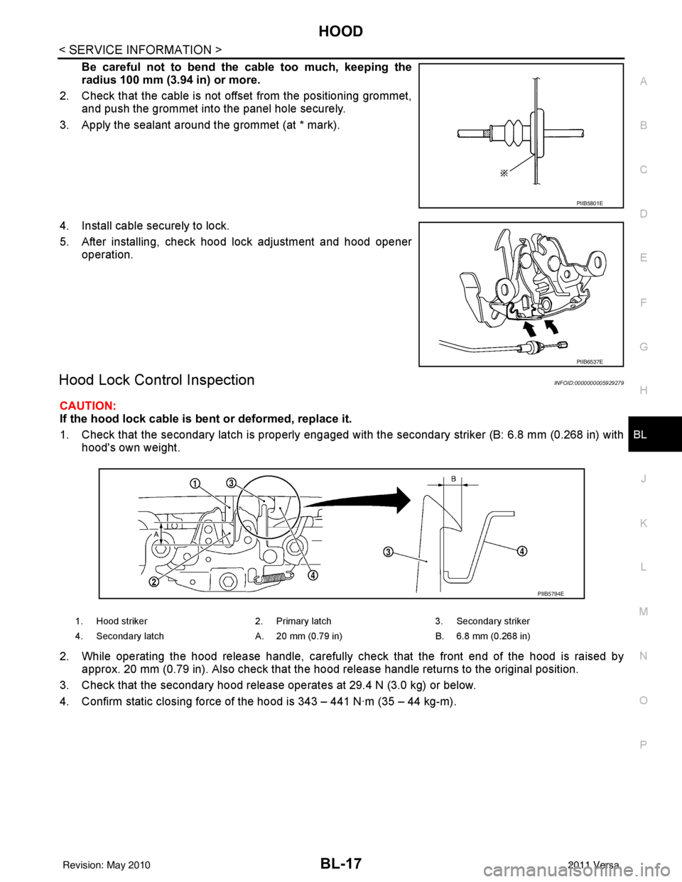
Be careful not to bend the cable too much, keeping the
radius 100 mm (3.94 in) or more.
2. Check that the cable is not of fset from the positioning grommet,
and push the grommet into the panel hole securely.
3. Apply the sealant around the grommet (at * mark).
4. Install cable securely to lock.
5. After installing, check hood lock adjustment and hood opener operation.
Hood Lock Control InspectionINFOID:0000000005929279
CAUTION:
If the hood lock cable is bent or deformed, replace it.
1. Check that the secondary latch is properly engaged with the secondary striker (B: 6.8 mm (0.268 in) with
hood's own weight.
2. While operating the hood release handle, carefully check that the front end of the hood is raised by
approx. 20 mm (0.79 in). Also check that the hood release handle returns to the original position.
3. Check that the secondary hood release operates at 29.4 N (3.0 kg) or below.
4. Confirm static closing force of the hood is 343 – 441 N·m (35 – 44 kg-m).
PIIB5801E
PIIB6537E
1. Hood striker 2. Primary latch 3. Secondary striker
4. Secondary latch A. 20 mm (0.79 in) B. 6.8 mm (0.268 in)
PIIB5794E
Revision: May 2010 2011 Versa
Page 529 of 3787

RADIATOR CORE SUPPORTBL-19
< SERVICE INFORMATION >
C
DE
F
G H
J
K L
M A
B
BL
N
O P
RADIATOR CORE SUPPORT
Removal and InstallationINFOID:0000000005929280
REMOVAL
Radiator Core Support Upper
1. Remove the air duct. Refer to EM-135, "Removal and Installation" .
2. Remove the headlamp (LH/RH). Refer to LT-25, "
Removal and Installation" .
3. Remove the hood lock assembly, and remove hood lock cable. Refer to BL-15
.
4. Remove the air guide and hood lock cable clip.
5. Remove the washer tank inlet. Refer to WW-25, "
Removal and Installation of Washer Tank" .
6. Remove the radiator core support upper.
Radiator Core Support Lower
1. Remove the air duct. Refer to EM-135, "Removal and Installation" .
2. Remove the front bumper. Refer to EI-15, "
Removal and Installation" .
3. Remove the headlamp (LH/RH). Refer to LT-25, "
Removal and Installation" .
4. Remove the hood lock assembly, and remove hood lock cable. Refer to BL-15
.
5. Remove the air guide and hood lock cable mounting clip.
6. Remove the front bumper reinforcement. Refer to EI-15, "
Removal and Installation" .
7. Remove the radiator core lower stay.
8. Remove the undercover.
PIIB6515E
1. Radiator core support upper 2. Radiator core support lower 3. Radiator core support lower stay
4. Radiator core support side stay 5. Air guide
24.5 N·m (2.5 kg-m, 18 ft-lb)
Revision: May 2010 2011 Versa
Page 531 of 3787

FRONT FENDERBL-21
< SERVICE INFORMATION >
C
DE
F
G H
J
K L
M A
B
BL
N
O P
FRONT FENDER
Removal and InstallationINFOID:0000000005929281
REMOVAL
1. Remove the headlamp assemblies. Refer to LT-25, "Removal and Installation".
2. Remove the cowl top cover (LH/RH). Refer to EI-24, "
Removal and Installation".
3. Remove the front fender protector. Refer to EI-26, "
Component".
4. Remove the bolt and the front fender.
CAUTION:
While removing use a shop cloth to pr otect the vechicle body from damage.
INSTALLATION
Installation is in the reverse order of removal.
CAUTION:
• After installing, apply touch-up paint on to the head of the front fender bolts.
• After installing, check front fender adjustment. Refer to BL-13, "
Fitting Adjustment" and BL-160, "Fit-
ting Adjustment".
1. Front fender 2 Bolt (LH 7 bolts required) (RH 8 bolts
required)
LIIA2657E
Revision: May 2010 2011 Versa
Page 533 of 3787

POWER DOOR LOCK SYSTEMBL-23
< SERVICE INFORMATION >
C
DE
F
G H
J
K L
M A
B
BL
N
O P
System DescriptionINFOID:0000000005929283
Power is supplied at all times
• through 40A fusible link (letter g, located in the fuse and fusible link box)
• to BCM terminal 70
• through 10A fuse [No. 8, located in the fuse block (J/B)]
• to BCM terminal 57
• through 10A fuse [No. 14, located in the fuse block (J/B)]
• to key switch terminal 2 (without Intelligent Key system)
• through 10A fuse [No. 31, located in the fuse block (J/B)]
• to key switch and ignition knob switch terminals 2 and 4 (with Intelligent Key system).
When key switch is ON (key is inserted in ignition key cylinder), power is supplied
• through key switch terminal 1 (without Intelligent Key system) or key switch and ignition knob terminal 1 (with Intelligent Key system)
• to BCM terminal 37.
Ground is supplied
• to BCM terminal 67
• through body grounds M57 and M61.
LOCK OPERATION
When the door is locked with main power window and door lock/unlock switch, ground is supplied
• to BCM terminal 45
• through main power window and door lock and unlock switch terminals 17 and 18
• through body grounds M57 and M61.
When the door is locked with power window and door lock/unlock switch RH, ground is supplied
• to BCM terminal 45
• through power window and door lock and unlock switch RH terminals 1 and 3
• through body grounds M57 and M61.
When the door is locked with front door lock assemb ly LH (key cylinder switch), ground is supplied
• to BCM terminal 8
• through front door lock assembly LH (key cylinder switch) terminals 4 and 6
• through body grounds M57 and M61.
UNLOCK OPERATION
When the door is unlocked with main power window and door lock/unlock switch, ground is supplied
• to BCM terminal 46
• through main power window and door lock/unlock switch terminals 6 and 17
• through body grounds M57 and M61.
When the door is unlocked with power window and door lock/unlock switch RH, ground is supplied
• to BCM terminal 46
• through power window and door lock and unlock switch RH terminals 2 and 3
• through body grounds M57 and M61.
When the door is unlocked with front door lock assemb ly LH (key cylinder switch), ground is supplied
• to BCM terminal 7
• through front door lock assembly LH (key cylinder switch) terminals 4 and 5
1. BCM M18, M19, M20
(view with glove box removed) 2. Intelligent Key unit M52
(if equipped) 3. Front door lock assembly LH (key cyl-
inder switch) D14
4. Front door switch LH B8, RH B108 5. Front door lock assembly LH (actuator) D14
Front door lock assembly RH (actuator)
D1146. Rear door switch LH B6, RH B116
7. Rear door lock actuator LH D205 RH D305 8. Key switch and ignition knob switch M73
(with A/T or CVT and Intelligent Key) 9. Key switch and ignition knob switch
M73 (with M/T and Intelligent Key)
10. Key switch and key lock solenoid M27 (without Intelligent key) 11. Main power window and door lock/un-
lock switch D7, D8
Power window and door lock/unlock
switch RH D105 12. Fuse block (with Intelligent Key)
(view with instrument panel LH re-
moved)
13. Passenger select unlock relay M2 (with Intelligent Key) 14. Back door lock assembly (back door
switch) D405 (hatchback view with back
door open) 15. Combination meter M24
Revision: May 2010
2011 Versa
Page 534 of 3787

BL-24
< SERVICE INFORMATION >
POWER DOOR LOCK SYSTEM
• through body grounds M57 and M61.
When the front door switch LH is ON (door is OPEN), ground is supplied
• to BCM terminal 47
• through front door switch LH terminal 2
• through front door switch LH case ground.
When the front door switch RH is ON (door is OPEN), ground is supplied
• to BCM terminal 12
• through front door switch RH terminal 2
• through front door switch RH case ground.
When the rear door switch LH is ON (door is OPEN), ground is supplied
• to BCM terminal 48
• through rear door switch LH terminal 1
• through rear door switch LH case ground.
When the rear door switch RH is ON (door is OPEN), ground is supplied
• to BCM terminal 13
• through rear door switch RH terminal 1
• through rear door switch RH case ground.
When the back door lock assembly (back door switch) ( hatchback) is ON (back door is OPEN), ground is sup-
plied
• to BCM terminal 43
• through back door lock assembly (back door switch) terminals 3 and 4
• through body grounds B117, B132 and D402.
OUTLINE
Functions available by operating the inside door lock and unlock switches
• Interlocked with the locking operation of door lock and unlock switch, door lock actuators of all doors are
locked.
• Interlocked with the unlocking operation of door lock and unlock switch, door lock actuators of all doors are
unlocked.
Functions available by operating the front door lock assembly LH (key cylinder switch)
• Interlocked with the locking operation of front door lock assembly LH (key cylinder switch), door lock actua-
tors of all doors are locked.
• When front door lock assembly LH (key cylinder switch) is unlocked, front door lock assembly LH (actuator)
is unlocked.
• When front door lock assembly LH (key cylinder swit ch) is unlocked for the second time within 5 seconds
after the first operation, front door lock assembly RH (actuator), rear door lock actuator LH and rear door
lock actuator RH are unlocked.
Key reminder door system
When door lock and unlock switch is operated to lock doors with ignition key inserted in key cylinder and any
door open, all door lock actuators are locked and then unlocked.
AUTOMATIC DOOR LOCKS (LOCK OPERATION)
The interlock door lock function is the function that locks all doors linked with the vehicle speed.
Vehicle Speed Sensing Auto Door Lock*1
All doors are locked when the vehicle speed reaches 24 km/h (15 MPH) or more.
BCM outputs the lock signal to all door lock actuators when it detects that the ignition switch is turned ON, all
doors are closed and the vehicle speed received from the combination meter via CAN communication
becomes 15 MPH (24 km/h) or more.
If a door is opened and closed at any time during one ignition cycle (OFF → ON), even after initial auto door
lock has taken place, the BCM will relock all doors when the vehicle speed reaches 15 MPH (24 km/h) or more
again.
Setting change of Automatic Door Locks (LOCK) Function
The lock operation setting of the autom atic door locks function can be changed.
With CONSULT-III
The ON/OFF switching of the automatic door locks (LOC K) function and the type selection of the automatic
door locks (LOCK) function can be performed at the WO RK SUPPORT setting of CONSULT-III. Refer to BL-
41, "CONSULT-III Function (BCM)".
Without CONSULT- III
The automatic door locks (LOCK) function can be swit ched ON/OFF by performing the following operation.
Revision: May 2010 2011 Versa