2011 NISSAN TIIDA RON 91
[x] Cancel search: RON 91Page 557 of 3787
POWER DOOR LOCK SYSTEMBL-47
< SERVICE INFORMATION >
C
DE
F
G H
J
K L
M A
B
BL
N
O P
Door Switch Check (Sedan)INFOID:0000000005929295
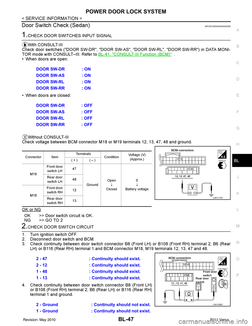
1.CHECK DOOR SWITCHES INPUT SIGNALWith CONSULT-III
Check door switches ("DOOR SW-DR", "DOOR SW-AS" , "DOOR SW-RL", "DOOR SW-RR") in DATA MONI-
TOR mode with CONSULT–III. Refer to BL-41, "
CONSULT-III Function (BCM)" .
• When doors are open:
• When doors are closed:
Without CONSULT-III
Check voltage between BCM connector M18 or M19 terminals 12, 13, 47, 48 and ground.
OK or NG
OK >> Door switch circuit is OK.
NG >> GO TO 2
2.CHECK DOOR SWITCH CIRCUIT
1. Turn ignition switch OFF.
2. Disconnect door switch and BCM.
3. Check continuity between door switch connector B8 (F ront LH) or B108 (Front RH) terminal 2, B6 (Rear
LH) or B116 (Rear RH) terminal 1 and BCM connector M18, M19 terminals 12, 13, 47 and 48.
4. Check continuity between door switch connector B8 (Front LH) or B108 (Front RH) terminal 2, B6 (Rear LH) or B116 (Rear RH)
terminal 1 and ground.DOOR SW-DR : ON
DOOR SW-AS : ON
DOOR SW-RL : ON
DOOR SW-RR : ON
DOOR SW-DR : OFF
DOOR SW-AS : OFF
DOOR SW-RL : OFF
DOOR SW-RR : OFF
Connector Item
Te r m i n a l s
ConditionVoltage (V)
(Approx.)
( + ) ( – )
M19 Front door
switch LH 47
Ground Open
↓
Closed 0
↓
Battery voltage
Rear door
switch LH 48
M18 Front door
switch RH 12
Rear door
switch RH 13
LIIA1177E
2 - 47
: Continuity should exist.
2 - 12 : Continuity should exist.
1 - 48 : Continuity should exist.
1 - 13 : Continuity should exist.
2 - Ground : Continuity should not exist.
1 - Ground : Continuity should not exist.
LIIA1350E
Revision: May 2010 2011 Versa
Page 558 of 3787
BL-48
< SERVICE INFORMATION >
POWER DOOR LOCK SYSTEM
OK or NG
OK >> GO TO 3
NG >> Repair or replace harness.
3.CHECK DOOR SWITCHES
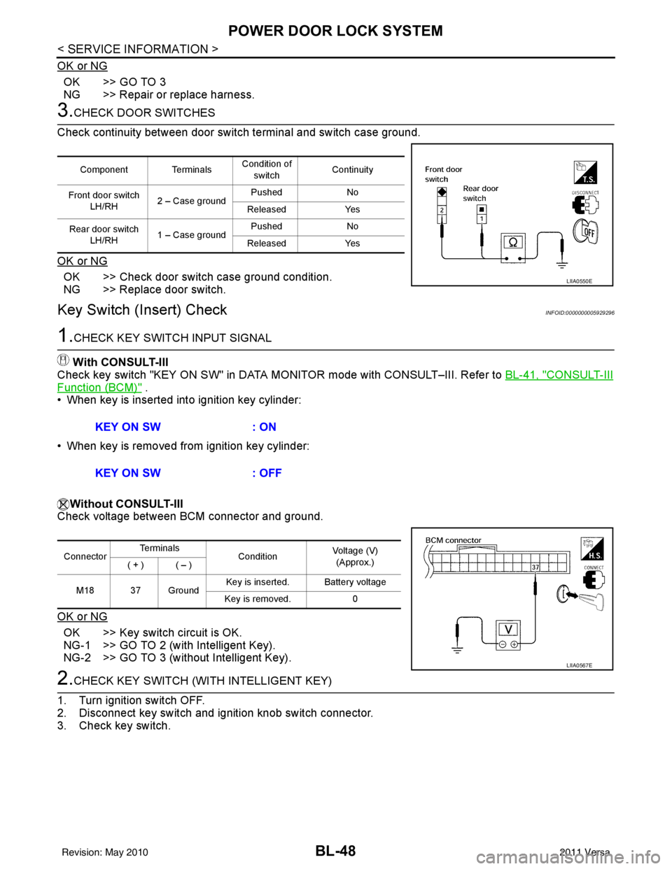
Check continuity between door switch terminal and switch case ground.
OK or NG
OK >> Check door switch case ground condition.
NG >> Replace door switch.
Key Switch (I nsert) CheckINFOID:0000000005929296
1.CHECK KEY SWITCH INPUT SIGNAL
With CONSULT-III
Check key switch "KEY ON SW" in DATA MONITOR mode with CONSULT–III. Refer to BL-41, "
CONSULT-III
Function (BCM)" .
• When key is inserted into ignition key cylinder:
• When key is removed from ignition key cylinder:
Without CONSULT-III
Check voltage between BCM connector and ground.
OK or NG
OK >> Key switch circuit is OK.
NG-1 >> GO TO 2 (with Intelligent Key).
NG-2 >> GO TO 3 (without Intelligent Key).
2.CHECK KEY SWITCH (WITH INTELLIGENT KEY)
1. Turn ignition switch OFF.
2. Disconnect key switch and ignition knob switch connector.
3. Check key switch.
Component Terminals Condition of
switch Continuity
Front door switch LH/RH 2 – Case ground Pushed
No
Released Yes
Rear door switch LH/RH 1 – Case ground Pushed
No
Released Yes
LIIA0550E
KEY ON SW : ON
KEY ON SW : OFF
ConnectorTe r m i n a l s
ConditionVoltage (V)
(Approx.)
( + ) ( – )
M18 37 Ground Key is inserted. Battery voltage
Key is removed. 0
LIIA0567E
Revision: May 2010 2011 Versa
Page 562 of 3787
BL-52
< SERVICE INFORMATION >
POWER DOOR LOCK SYSTEM
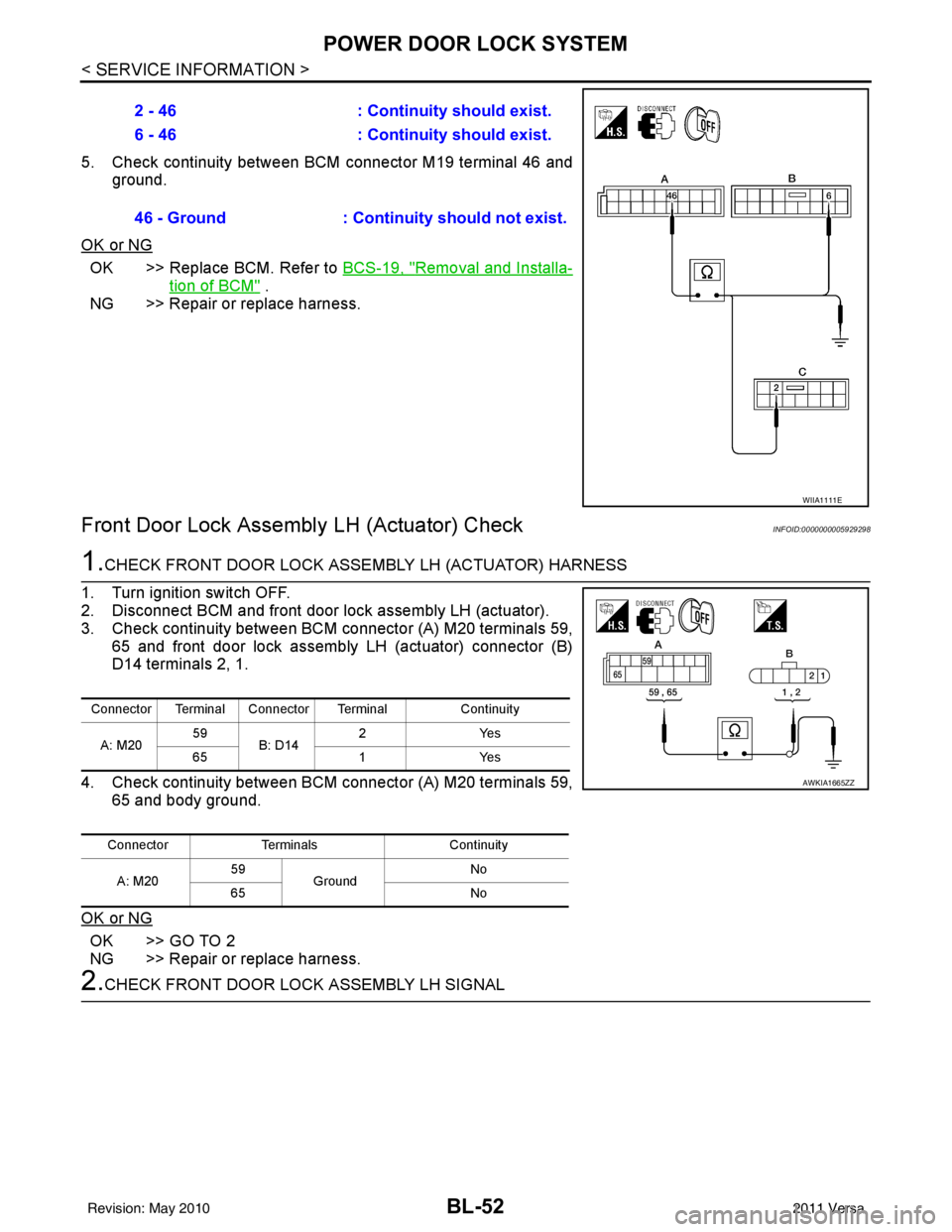
5. Check continuity between BCM connector M19 terminal 46 andground.
OK or NG
OK >> Replace BCM. Refer to BCS-19, "Removal and Installa-
tion of BCM" .
NG >> Repair or replace harness.
Front Door Lock Assembly LH (Actuator) CheckINFOID:0000000005929298
1.CHECK FRONT DOOR LOCK ASSEMBLY LH (ACTUATOR) HARNESS
1. Turn ignition switch OFF.
2. Disconnect BCM and front door lock assembly LH (actuator).
3. Check continuity between BCM connector (A) M20 terminals 59, 65 and front door lock assembly LH (actuator) connector (B)
D14 terminals 2, 1.
4. Check continuity between BCM connector (A) M20 terminals 59, 65 and body ground.
OK or NG
OK >> GO TO 2
NG >> Repair or replace harness.
2.CHECK FRONT DOOR LOCK ASSEMBLY LH SIGNAL 2 - 46
: Continuity should exist.
6 - 46 : Continuity should exist.
46 - Ground : Continuity should not exist.
WIIA1111E
Connector Terminal Connector Terminal Continuity
A: M20 59
B: D14 2Y
es
65 1Yes
Connector Terminals Continuity
A: M20 59
Ground No
65 No
AWKIA1665ZZ
Revision: May 2010 2011 Versa
Page 563 of 3787
POWER DOOR LOCK SYSTEMBL-53
< SERVICE INFORMATION >
C
DE
F
G H
J
K L
M A
B
BL
N
O P
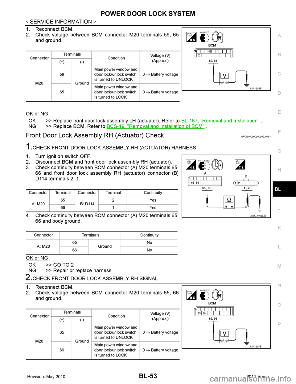
1. Reconnect BCM.
2. Check voltage between BCM connector M20 terminals 59, 65 and ground.
OK or NG
OK >> Replace front door lock assembly LH (actuator). Refer to BL-167, "Removal and Installation" .
NG >> Replace BCM. Refer to BCS-19, "
Removal and Installation of BCM" .
Front Door Lock Assembly RH (Actuator) CheckINFOID:0000000006220781
1.CHECK FRONT DOOR LOCK ASSEMBLY RH (ACTUATOR) HARNESS
1. Turn ignition switch OFF.
2. Disconnect BCM and front door lock assembly RH (actuator).
3. Check continuity between BCM connector (A) M20 terminals 65, 66 and front door lock assembly RH (actuator) connector (B)
D114 terminals 2, 1.
4. Check continuity between BCM connector (A) M20 terminals 65, 66 and body ground.
OK or NG
OK >> GO TO 2
NG >> Repair or replace harness.
2.CHECK FRONT DOOR LOCK ASSEMBLY RH SIGNAL
1. Reconnect BCM.
2. Check voltage between BCM connector M20 terminals 65, 66 and ground.
Connector Te r m i n a l s
ConditionVoltage (V)
(Approx.)
(+) (-)
M20 59
Ground Main power window and
door lock/unlock switch
is turned to UNLOCK
0
→ Battery voltage
65 Main power window and
door lock/unlock switch
is turned to LOCK 0
→ Battery voltage
LIIA1355E
Connector Terminal Connector Terminal Continuity
A: M20 65
B: D114 2Y
es
66 1Yes
Connector Terminals Continuity
A: M20 65
Ground No
66 No
AWKIA1666ZZ
ConnectorTe r m i n a l s
ConditionVoltage (V)
(Approx.)
(+) (-)
M20 65
Ground Main power window and
door lock/unlock switch
is turned to UNLOCK
0
→ Battery voltage
66 Main power window and
door lock/unlock switch
is turned to LOCK
0
→ Battery voltage
LIIA1357E
Revision: May 2010 2011 Versa
Page 564 of 3787

BL-54
< SERVICE INFORMATION >
POWER DOOR LOCK SYSTEM
OK or NG
OK >> Replace front door lock assembly RH (actuator). Refer to BL-167, "Removal and Installation" .
NG >> Replace BCM. Refer to BCS-19, "
Removal and Installation of BCM" .
Rear Door Lock Actuator LH/RH CheckINFOID:0000000005929299
1.CHECK DOOR LOCK ACTUATOR HARNESS
NOTE:
For models with Intelligent Key, insure that passenger select unlock relay remains connected during this test.
1. Turn ignition switch OFF.
2. Disconnect BCM and each door lock actuator.
3. Check continuity between BCM connector (A) M20 terminals 65, 66 and rear door lock actuator RH connector (B) D305, rear
door lock actuator LH connector (C) D205 terminals 2, 3.
4. Check continuity between BCM connector (A) M20 terminals 65, 66 and body ground.
OK or NG
OK >> GO TO 2
NG >> Check the following: • Without Intelligent Key: Repair or replace harness.
• With Intelligent Key: Repair or replace harness or pas-senger select unlock relay.
2.CHECK DOOR LOCK ACTUATOR SIGNAL
1. Reconnect BCM.
2. Check voltage between BCM connector M20 terminals 65, 66 and ground.
OK or NG
OK >> Replace rear door lock actuator LH/RH. Refer to BL-170, "Removal and Installation" .
NG >> Replace BCM. Refer to BCS-19, "
Removal and Installation of BCM" .
Front Door Lock Assembly LH (Key Cylinder Switch) CheckINFOID:0000000005929300
1.CHECK FRONT DOOR LOCK ASSEMB LY LH (KEY CYLINDER SWITCH)
With CONSULT-III
Connector Terminal Connector Terminal Continuity
A: M20 65
B: D305
C: D205 3Y
es
66 2Yes
Connector Terminals Continuity
A: M20 65
Ground No
66 No
LIIA2526E
ConnectorTe r m i n a l s
ConditionVoltage (V)
(Approx.)
(+) (-)
M20 65
Ground Main power window and
door lock/unlock switch is
turned to UNLOCK
0
→ Battery voltage
66 Main power window and
door lock/unlock switch is
turned to LOCK 0
→ Battery voltage
LIIA1357E
Revision: May 2010 2011 Versa
Page 565 of 3787
POWER DOOR LOCK SYSTEMBL-55
< SERVICE INFORMATION >
C
DE
F
G H
J
K L
M A
B
BL
N
O P
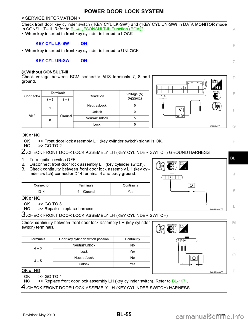
Check front door key cylinder switch ("KEY CYL LK -SW") and ("KEY CYL UN-SW) in DATA MONITOR mode
in CONSULT–III. Refer to BL-41, "
CONSULT-III Function (BCM)" .
• When key inserted in front key cylinder is turned to LOCK:
• When key inserted in front key cylinder is turned to UNLOCK:
Without CONSULT-III
Check voltage between BCM connector M18 terminals 7, 8 and
ground.
OK or NG
OK >> Front door lock assembly LH (key cylinder switch) signal is OK.
NG >> GO TO 2
2.CHECK FRONT DOOR LOCK ASSEMBLY LH (KEY CYLINDER SWITCH) GROUND HARNESS
1. Turn ignition switch OFF.
2. Disconnect front door lock assembly LH (key cylinder switch).
3. Check continuity between front door lock assembly LH (key cyl- inder switch) connector D14 terminal 4 and body ground.
OK or NG
OK >> GO TO 3
NG >> Repair or replace harness.
3.CHECK FRONT DOOR LOCK ASSEM BLY LH (KEY CYLINDER SWITCH)
Check continuity between front door lock assembly LH (key cylinder
switch) terminals.
OK or NG
OK >> GO TO 4
NG >> Replace front door lock assembly LH (key cylinder switch). Refer to BL-167
.
4.CHECK FRONT DOOR LOCK ASSEMBLY LH (KEY CYLINDER SWITCH) HARNESS
KEY CYL LK-SW : ON
KEY CYL UN-SW : ON
Connector
Te r m i n a l s
ConditionVoltage (V)
(Approx.)
( + ) ( – )
M18 7
Ground Neutral/Lock
5
Unlock 0
8 Neutral/Unlock
5
Lock 0
WIIA1247E
Connector TerminalsContinuity
D14 4 – Ground Yes
AWKIA1667ZZ
Terminals Door key cylinder switch position Continuity
4 – 6 Neutral/Unlock
No
Lock Yes
4 – 5 Neutral/Lock
No
Unlock Yes
AWKIA1668ZZ
Revision: May 2010 2011 Versa
Page 566 of 3787

BL-56
< SERVICE INFORMATION >
POWER DOOR LOCK SYSTEM
1. Disconnect BCM connector M18.
2. Check continuity between BCM connector (A) M18 terminals 7,8 and front door lock assembly LH (key cylinder switch) connec-
tor (B) D14 terminals 5, 6 and body ground.
OK or NG
OK >> Front door lock assembly LH (key cylinder switch) circuit is OK.
NG >> Repair or replace harness.
Passenger Select Unlock Relay Circuit Inspection (With Intelligent Key)INFOID:0000000005929301
1.CHECK PASSENGER SELECT UNLOCK RELAY CIRCUIT
NOTE:
Passenger select unlock relay must remain connected during this step.
1. Turn ignition switch OFF.
2. Disconnect BCM and inoperative rear door lock actuator.
3. Check continuity between BCM connector (A) M20 terminal 65 and rear door lock actuator LH connector (B) D205 terminal 3 or
rear door lock actuator RH connector (C) D305 Terminal 3.
4. Check continuity between BCM connector (A) M20 terminal 65 and body ground.
OK or NG
OK >> GO TO 4
NG >> GO TO 2
2.CHECK PASSENGER SELECT UNLOCK RELAY INPUT
1. Disconnect passenger select unlock relay.
2. Check continuity between BCM connector (A) M20 terminal 65 and passenger select unlock relay connector (B) M2 terminal 3.
3. Check continuity between BCM connector (A) M20 terminal 65 and body ground.
OK or NG
OK >> GO TO 3
NG >> Repair or replace harness between BCM and relay.
3.CHECK PASSENGER SELECT UNLOCK RELAY OUTPUT
Connector Terminal Connector Terminal Continuity
A: M18 7
B: D14 5Y
es
86Y es
7G ro u nd N o
8G ro u nd N o
AWKIA1669ZZ
65 - 3 : Continuity should exist.
65 - Ground : Continuity should not exist.
WIIA1164E
65 - 3 : Continuity should exist.
65 - Ground : Continuity should not exist.
WIIA1165E
Revision: May 2010 2011 Versa
Page 568 of 3787
BL-58
< SERVICE INFORMATION >
REMOTE KEYLESS ENTRY SYSTEM
REMOTE KEYLESS ENTRY SYSTEM
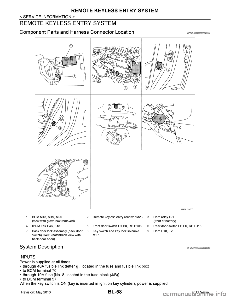
Component Parts and Harness Connector LocationINFOID:0000000005929302
System DescriptionINFOID:0000000005929303
INPUTS
Power is supplied at all times
• through 40A fusible link (letter g , located in the fuse and fusible link box)
• to BCM terminal 70
• through 10A fuse [No. 8, located in the fuse block (J/B)]
• to BCM terminal 57.
When the key switch is ON (key is inserted in ignition key cylinder), power is supplied
ALKIA1754ZZ
1. BCM M18, M19, M20
(view with glove box removed) 2. Remote keyless entry receiver M23 3. Horn relay H-1
(front of battery)
4. IPDM E/R E46, E48 5. Front door switch LH B8, RH B108 6. Rear door switch LH B6, RH B116
7. Back door lock assembly (back door switch) D405 (hatchback view with
back door open) 8. Key switch and key lock solenoid
M27 9. Horn E18, E20
Revision: May 2010
2011 Versa