2011 NISSAN TIIDA battery
[x] Cancel search: batteryPage 3655 of 3787
![NISSAN TIIDA 2011 Service Repair Manual TROUBLE DIAGNOSISSRS-21
< SYMPTOM DIAGNOSIS >
C
DE
F
G
I
J
K L
M A
B
SRS
N
O P
CONSULT-III Diagnostic Code
Chart ("SELF-DIAG [CURRENT]")
Diagnostic item Explanation Repair order
Recheck SRS at each r NISSAN TIIDA 2011 Service Repair Manual TROUBLE DIAGNOSISSRS-21
< SYMPTOM DIAGNOSIS >
C
DE
F
G
I
J
K L
M A
B
SRS
N
O P
CONSULT-III Diagnostic Code
Chart ("SELF-DIAG [CURRENT]")
Diagnostic item Explanation Repair order
Recheck SRS at each r](/manual-img/5/57396/w960_57396-3654.png)
TROUBLE DIAGNOSISSRS-21
< SYMPTOM DIAGNOSIS >
C
DE
F
G
I
J
K L
M A
B
SRS
N
O P
CONSULT-III Diagnostic Code
Chart ("SELF-DIAG [CURRENT]")
Diagnostic item Explanation Repair order
Recheck SRS at each replacement
NO DTC IS DETECTED Malfunction is indicat-
ed by the “AIR BAG”
warning lamp in User
mode.Low battery voltage (Less than 9V) 1. Go to
SC-5, "
How to Handle Bat-
tery".
2. Go to "DIAGNOSTIC PROCE-
DURE 3" .
“SELF-DIAG [PAST]” memory might
not be erased. Go to "DIAGNOSTIC PROCEDURE 4"
.
Intermittent malfunction has been
detected in the past. Go to "DIAGNOSTIC PROCEDURE 5"
.
No malfunction is detected in User mode. —
DRIVER AIRBAG MODULE [OPEN]
[B1049] or [B1054] Driver air bag module circuit is open (including the spiral ca-
ble).
1. Visually check the wiring harness
connection.
2. Replace the harness if it has visi- ble damage.
3. Replace driver air bag module.
4. Replace the spiral cable.
5. Replace the air bag diagnosis sensor unit.
6. Replace the related harness.
DRIVER AIRBAG MODULE
[VB-SHORT]
[B1050] or [B1055] Driver air bag module circuit is shorted to some power supply
circuit (including the spiral cable).
DRIVER AIRBAG MODULE [GND-SHORT]
[B1051] or [B1056] Driver air bag module circuit is shorted to ground (including
the spiral cable).
DRIVER AIRBAG MODULE [SHORT]
[B1052] or [B1057] Driver air bag module circuits are shorted to each other.
ASSIST A/B MODULE [OPEN]
[B1065] or [B1070] Front passenger air bag module circuit is open.
1. Visually check the wiring harness
connection.
2. Replace the harness if it has visi- ble damage.
3. Replace front passenger air bag
module.
4. Replace the air bag diagnosis sensor unit.
5. Replace the related harness.
ASSIST A/B MODULE
[VB-SHORT]
[B1066] or [B1071] Front passenger air bag module circuit is shorted to some
power supply circuit.
ASSIST A/B MODULE [GND-SHORT]
[B1067] or [B1072] Front passenger air bag module circuit is shorted to ground.
ASSIST A/B MODULE [SHORT]
[B1068] or [B1073] Front passenger air bag module circuits are shorted to each
other.
CRASH ZONE SEN [UNIT FAIL]
[B1033] or [B1034]
CRASH ZONE SEN [COMM FAIL][B1035] Crash zone sensor
1. Visually check the wiring harness
connection.
2. Replace the harness if it has visi- ble damage.
3. Replace the crash zone sensor.
4. Replace the air bag diagnosis sensor unit.
5. Replace the related harness.
SIDE MODULE LH [OPEN][B1134] Front LH side air bag module circuit is open.
1. Visually check the wiring harness
connection.
2. Replace the harness if it has visi-
ble damage.
3. Replace front LH seat back as- sembly (front LH side air bag
module).
4. Replace the air bag diagnosis sensor unit.
5. Replace the related harness.
SIDE MODULE LH
[VB-SHORT][B1135] Front LH side air bag module circuit is shorted to some power
supply circuit.
SIDE MODULE LH [GND-SHORT]
[B1136] Front LH side air bag module circuit is shorted to ground.
SIDE MODULE LH [SHORT][B 11
37] Front LH side air bag module circuits are shorted to each oth-
er.
Revision: May 2010
2011 Versa
Page 3659 of 3787

TROUBLE DIAGNOSISSRS-25
< SYMPTOM DIAGNOSIS >
C
DE
F
G
I
J
K L
M A
B
SRS
N
O P
2. Touch “TROUBLE DIAG RECORD”. NOTE:
With “TROUBLE DIAG RECORD”, di agnosis results previously erased by a reset operation can be
displayed.
3. Diagnostic code is displayed on “TROUBLE DIAG RECORD”.
4. Touch “PRINT”.
5. Compare diagnostic codes to "CONSULT-III Diagnos tic Code Chart ("SELF-DIAG [PAST]" or "TROUBLE
DIAG RECORD")".
6. Touch “BACK” key of CONSULT- III until “SELECT SYSTEM” appears.
7. Turn ignition switch OFF, then turn off and disconnect CONSULT-III, and both battery cables.
8. Repair the system as outlined by the “Repair orde r” in “Intermittent Malfunction Diagnostic Code Chart”,
that corresponds to the self-diagnostic result. For r eplacement procedure of component parts, refer to the
Removal and Installation procedure for the appropriate component.
9. Go to "DIAGNOSTIC PROCEDURE 3", for final checking.
CONSULT-III Diagnostic Code Chart ("SELF-DI AG [PAST]" or "TROUBLE DIAG RECORD")
Diagnostic item Explanation Repair order
Recheck SRS at each replacement
NO DTC IS DETECTED When malfunction is
indicated by the “AIR
BAG” warning lamp in
User mode.
• Low battery voltage (L
ess than 9V) • Go to "DIAGNOSTIC PROCEDURE
3" .
• Self-diagnostic result “SELF-DIAG [PAST]” (previously stored in the
memory) might not be erased after
repair.
• Intermittent malfunction has been detected in the past. • Go to "DIAGNOSTIC PROCEDURE
4" .
• Go to "DIAGNOSTIC PROCEDURE
5" .
• No malfunction is detected. —
DRIVER AIRBAG MODULE [OPEN]
[B1049] or [B1054] Driver air bag module circuit is open (including the spiral ca-
ble).
1. Visually check the wiring harness
connection.
2. Replace the harness if it has visi- ble damage.
3. Replace driver air bag module.
4. Replace the spiral cable.
5. Replace the air bag diagnosis sensor unit.
6. Replace the related harness.
DRIVER AIRBAG MODULE
[VB-SHORT]
[B1050] or [B1055] Driver air bag module circuit is shorted to some power supply
circuit (including the spiral cable).
DRIVER AIRBAG MODULE [GND-SHORT]
[B1051] or [B1056] Driver air bag module circuit is shorted to ground (including
the spiral cable).
DRIVER AIRBAG MODULE [SHORT]
[B1052] or [B1057] Driver air bag module circuits are shorted to each other.
ASSIST A/B MODULE [OPEN]
[B1065] or [B1070] Front passenger air bag module circuit is open.
1. Visually check the wiring harness
connection.
2. Replace the harness if it has visi-
ble damage.
3. Replace front passenger air bag module.
4. Replace the air bag diagnosis sensor unit.
5. Replace the related harness.
ASSIST A/B MODULE
[VB-SHORT]
[B1066] or [B1071] Front passenger air bag module circuit is shorted to some
power supply circuit.
ASSIST A/B MODULE [GND-SHORT]
[B1067] or [B1072] Front passenger air bag module circuit is shorted to ground.
ASSIST A/B MODULE [SHORT]
[B1068] or [B1073] Front passenger air bag module circuits are shorted to each
other.
Revision: May 2010
2011 Versa
Page 3668 of 3787
SRS-34
< ON-VEHICLE REPAIR >
DRIVER AIR BAG MODULE
ON-VEHICLE REPAIR
DRIVER AIR BAG MODULE
Removal and InstallationINFOID:0000000005931211
REMOVAL
WARNING:
• When servicing the SRS, do not work from directly in front of air bag module.
• Always place air bag module with pad side facing upward.
CAUTION:
• Before servicing the SRS, turn ignition switch OFF, discon-
nect both battery terminals, then wait at least three minutes.
• Do not attempt to repair or replace damaged direct-connect
SRS component connectors. If a driver air bag direct-connect
harness connector is damaged, the spiral cable must be
replaced.
• Do not insert any foreign object s (screwdriver, etc.) into air
bag module or harness connectors.
• Do not disassemble air bag module.
• Do not expose the air bag module to temperatures exceeding
90° C (194° F).
• Replace the air bag module if it has been dropped or sus-
tained an impact.
• Do not allow oil, grease or water to come in contact with the
air bag module.
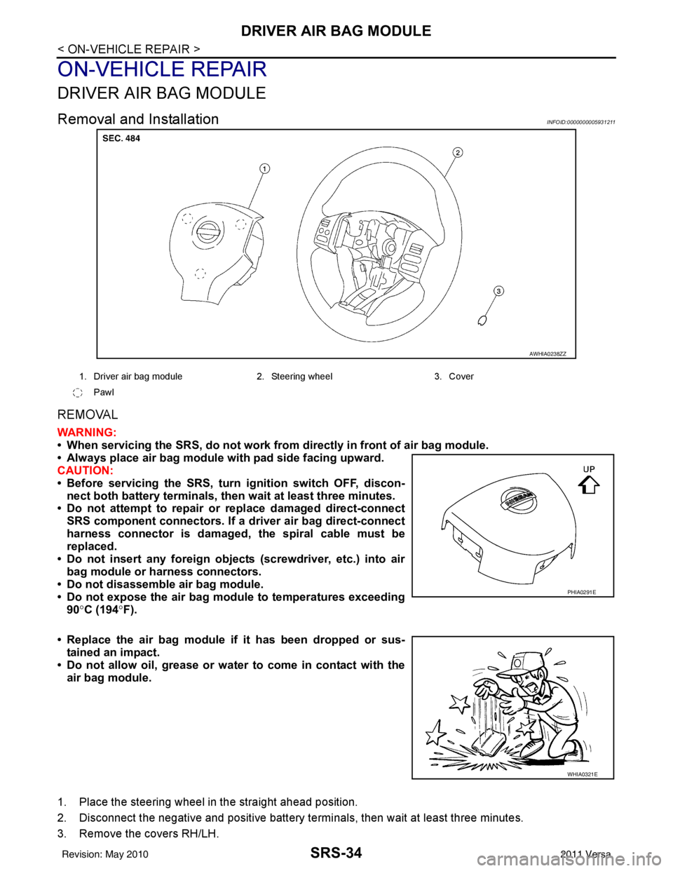
1. Place the steering wheel in the straight ahead position.
2. Disconnect the negative and positive battery termi nals, then wait at least three minutes.
3. Remove the covers RH/LH.
AWHIA0238ZZ
1. Driver air bag module 2. Steering wheel 3. Cover
Pawl
PHIA0291E
WHIA0321E
Revision: May 2010 2011 Versa
Page 3671 of 3787
SPIRAL CABLESRS-37
< ON-VEHICLE REPAIR >
C
DE
F
G
I
J
K L
M A
B
SRS
N
O P
SPIRAL CABLE
Removal and InstallationINFOID:0000000005931212
REMOVAL
WARNING:
When servicing the SRS, do not work from directly in front of air bag module.
CAUTION:
• Before servicing the SRS, turn ignition switch OFF, disconnect both battery terminals and wait at
least three minutes.
• Do not tap or bump the steering wheel.
• Do not disassemble the spiral cable.
• Do not allow oil, grease or water to co me in contact with the spiral cable.
• Replace the spiral cable if it has b een dropped or sustained an impact.
• With the steering linkage disconn ected, the spiral cable may snap by turning the steering wheel
beyond the limited number of turns. The spiral cable can be turned counterclockwise about 2.5 turns
from the neutral position.
1. Set the front wheels to the straight-ahead/neutral position.
2. Disconnect the negative and positive battery term inals, then wait at least three minutes.
3. Remove the steering wheel. Refer to PS-7, "
Removal and Installation".
4. Remove the column cover upper and lower.
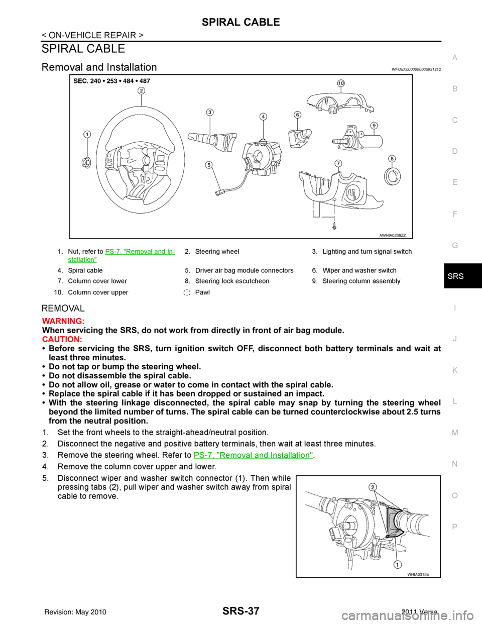
5. Disconnect wiper and washer switch connector (1). Then while pressing tabs (2), pull wiper and washer switch away from spiral
cable to remove.
AWHIA0239ZZ
1. Nut, refer to PS-7, "Removal and In-
stallation"
2. Steering wheel 3. Lighting and turn signal switch
4. Spiral cable 5. Driver air bag module connectors 6. Wiper and washer switch
7. Column cover lower 8. Steering lock escutcheon 9. Steering column assembly
10. Column cover upper Pawl
WHIA0315E
Revision: May 2010 2011 Versa
Page 3673 of 3787
FRONT PASSENGER AIR BAG MODULESRS-39
< ON-VEHICLE REPAIR >
C
DE
F
G
I
J
K L
M A
B
SRS
N
O P
FRONT PASSENGER AIR BAG MODULE
Removal and InstallationINFOID:0000000005931213
REMOVAL
WARNING:
• When servicing the SRS, do not work from directly in front of air bag module.
• Always place front passenger air bag modu le with pad side facing upward.
CAUTION:
• Before servicing SRS, turn the ig nition switch OFF, disconnect both battery terminals and wait at
least three minutes.
• Do not use old bolts after removal; replace with new bolts.
• Do not insert any foreign objects (screwdriver, etc.) into air bag module or harness connectors.
• Do not disassemble air bag module.
• Do not expose the front passenger air bag module to temperatures exceeding 90 °C (194° F).
• Replace the front passenger air bag module if it has been
dropped or sustained an impact.
• Do not allow oil, grease or water to come in contact with the front passenger air bag module.
1. Disconnect the negative and positive battery term inals, then wait at least three minutes.
2. Remove the side ventilator assembly (right). Refer to IP-11
.
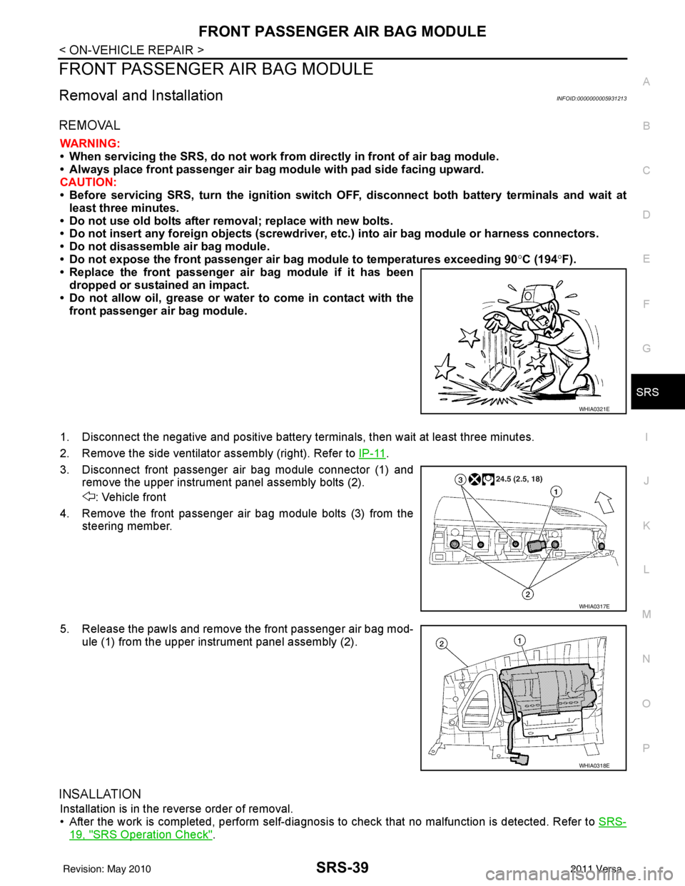
3. Disconnect front passenger air bag module connector (1) and remove the upper instrument panel assembly bolts (2).
: Vehicle front
4. Remove the front passenger air bag module bolts (3) from the steering member.
5. Release the pawls and remove the front passenger air bag mod- ule (1) from the upper instrument panel assembly (2).
INSALLATION
Installation is in the reverse order of removal.
• After the work is completed, perform self-diagnosis to check that no malfunction is detected. Refer to SRS-
19, "SRS Operation Check".
WHIA0321E
WHIA0317E
WHIA0318E
Revision: May 2010 2011 Versa
Page 3675 of 3787
SIDE CURTAIN AIR BAG MODULESRS-41
< ON-VEHICLE REPAIR >
C
DE
F
G
I
J
K L
M A
B
SRS
N
O P
• When servicing the SRS, do not work from directly in front of air bag module.
• Always place the curtain air bag module with deployment side facing upward.
• Do not reuse center pillar upper garnish if removed.
CAUTION:
• Before servicing SRS, turn the ig nition switch OFF, disconnect both battery terminals and wait at
least three minutes.
• Do not use old bolts after removal; replace with new bolts.
• Do not insert any foreign objects (screwdriver, etc.) into air bag module or harness connectors.
• Do not disassemble air bag module.
• Do not expose the side curtain air bag module to temperatures exceeding 90 °C (194 °F).
• Replace the side curtain air bag module if it has been dropped or sustained an impact.
• Do not allow oil, grease or water to come in contact with the
side curtain air bag module.
• Do not attempt to repair or replace damaged direct-connect SRS component connectors. If a direct-connect harness con-
nector is damaged, the harness must be replaced.
1. Disconnect both the negative and positive battery te rminals, then wait at least three minutes.
2. Remove the headlining. Refer to EI-50
.
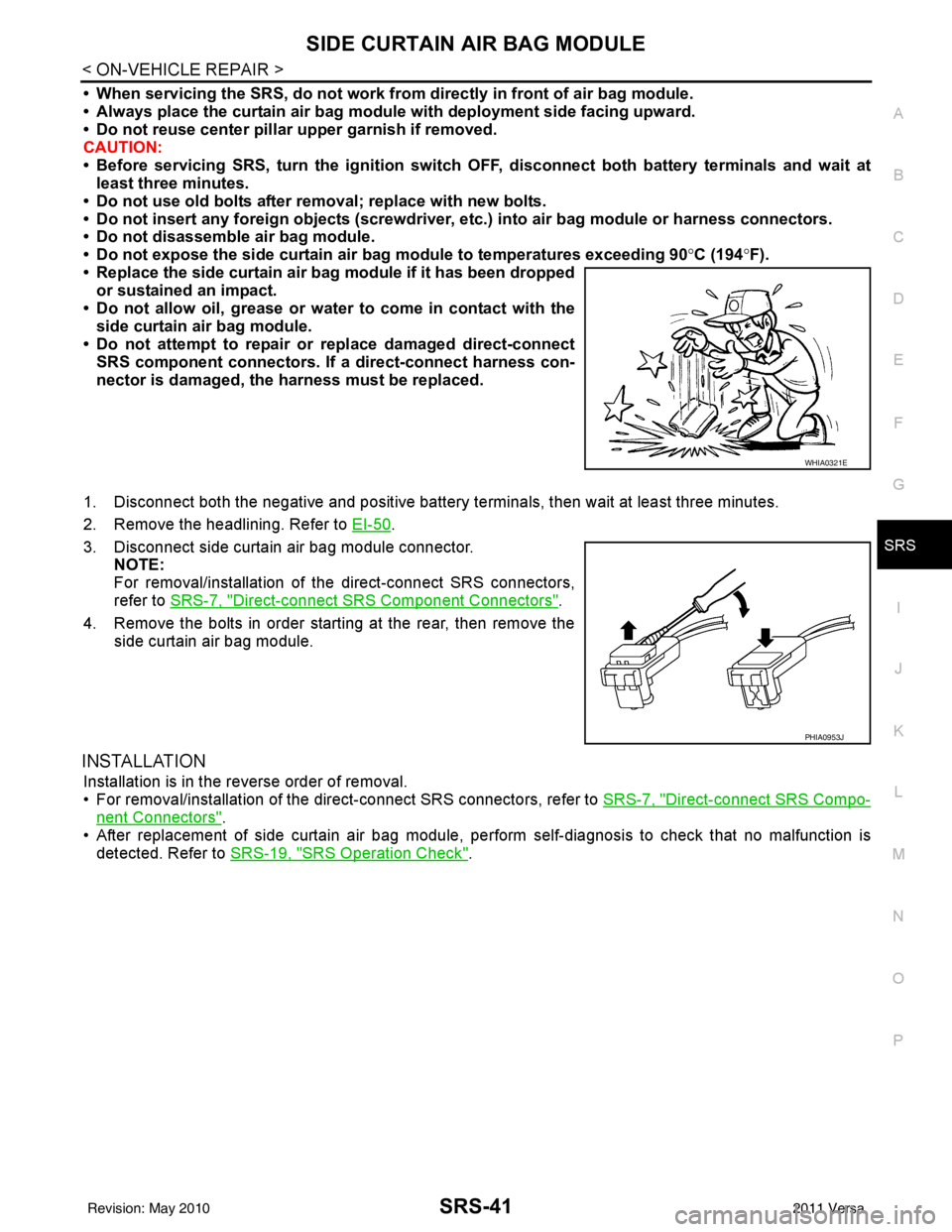
3. Disconnect side curtain air bag module connector. NOTE:
For removal/installation of the direct-connect SRS connectors,
refer to SRS-7, "
Direct-connect SRS Component Connectors".
4. Remove the bolts in order starting at the rear, then remove the side curtain air bag module.
INSTALLATION
Installation is in the reverse order of removal.
• For removal/installation of the direct-connect SRS connectors, refer to SRS-7, "
Direct-connect SRS Compo-
nent Connectors".
• After replacement of side curtain air bag module, per form self-diagnosis to check that no malfunction is
detected. Refer to SRS-19, "
SRS Operation Check".
WHIA0321E
PHIA0953J
Revision: May 2010 2011 Versa
Page 3676 of 3787
SRS-42
< ON-VEHICLE REPAIR >
CRASH ZONE SENSOR
CRASH ZONE SENSOR
Removal and InstallationINFOID:0000000005931216
REMOVAL
CAUTION:
• Before servicing the SRS, turn ignition switch OFF, disconnect both battery terminals and wait at
least three minutes.
• Do not disassemble the crash zone sensor.
• Do not use old nuts after removal; replace with new nuts.
• Replace the crash zone sensor if it has been dropped or sus- tained an impact.
• Check crash zone sensor to make sure it is free of deformi-
ties, dents, cracks or rust. If it shows any visible signs of dam-
age, replace it with a new one.
1. Disconnect both the negative and positive battery terminals, then wait at least three minutes.
2. Remove air intake duct. Refer to EM-25, "
Exploded View" (HR16DE), EM-135, "Component" (MR18DE).
3. Remove upper radiator cover and front grille, refer to EI-23
.
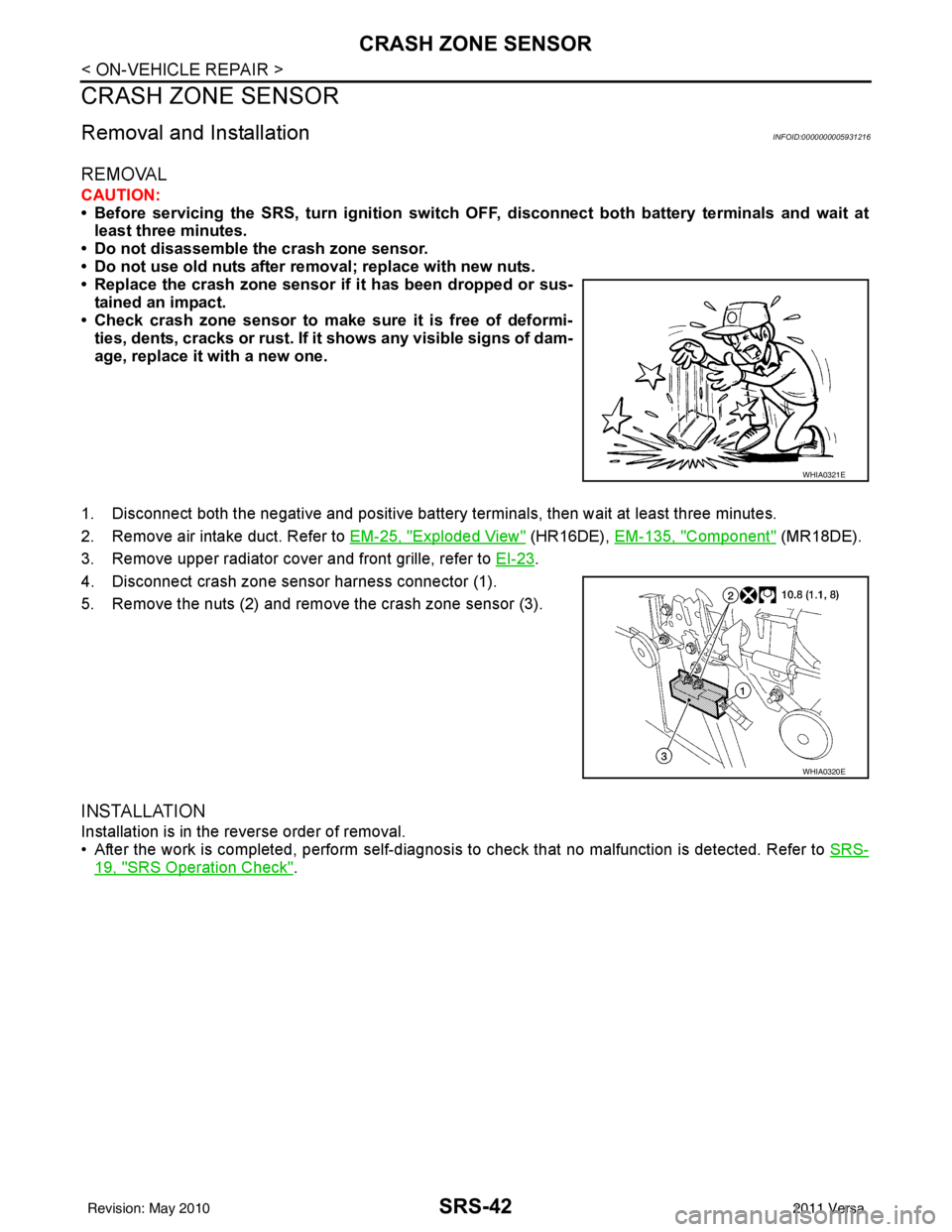
4. Disconnect crash zone sensor harness connector (1).
5. Remove the nuts (2) and remove the crash zone sensor (3).
INSTALLATION
Installation is in the reverse order of removal.
• After the work is completed, perform self-diagnosis to check that no malfunction is detected. Refer to SRS-
19, "SRS Operation Check".
WHIA0321E
WHIA0320E
Revision: May 2010 2011 Versa
Page 3677 of 3787
SIDE AIR BAG (SATELLITE) SENSORSRS-43
< ON-VEHICLE REPAIR >
C
DE
F
G
I
J
K L
M A
B
SRS
N
O P
SIDE AIR BAG (S ATELLITE) SENSOR
Removal and InstallationINFOID:0000000005931217
REMOVAL
WARNING:
Do not reuse center pillar upper garnish if removed.
CAUTION:
• Before servicing the SRS, turn ignition switch OFF, disconnect both battery terminals and wait at
least three minutes.
• Do not disassemble the side air bag (satellite) sensor.
• Do not use old nuts after removal; replace with new nuts.
• Replace the side air bag (satellite) sensor if it has been dropped or sustained an impact.
• Check side air bag (satellite) sensor to make sure it is free of deformities, dents, cracks or rust . If it shows any visible signs
of damage, replace it with a new one.
1. Disconnect both the negative and positive battery te rminals, then wait at least three minutes.
2. Remove the body side welt, kicking plate, and center pillar lower garnish. Refer to EI-41, "
Component".
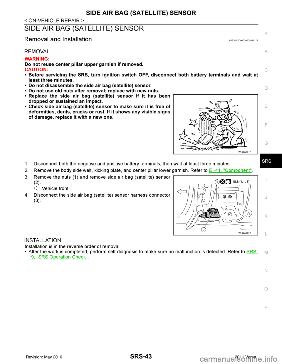
3. Remove the nuts (1) and remove side air bag (satellite) sensor (2).
: Vehicle front
4. Disconnect the side air bag (satellite) sensor harness connector (3).
INSTALLATION
Installation is in the reverse order of removal.
• After the work is completed, perform self-diagnosis to make sure no malfunction is detected. Refer to SRS-
19, "SRS Operation Check".
WHIA0321E
WHIA0322E
Revision: May 2010 2011 Versa